Using Mongoose OS on your ESP8266
The ESP8266 enjoyed great fanfare a few years ago. It was a cheap WiFi-enabled device that offered low power consumption, small size and a few GPIO pins.
Over time hackers got their hands on them and fully exploited what could be done with them, but for some remained a mystery. That was until Mongoose OS came on the scene, offering a simple way of flashing code to the board, and a simple API for fast prototyping.
In this project, we shall introduce Mongoose OS, an alternative firmware for your ESP8266, ESP32 devices that offers a simple platform for Internet of Things (IoT) projects. To take our knowledge further, we shall construct a simple hardware project that will alert us when the post arrives.
For this project, you will need
- A NodeMCU board
- A reed switch sensor
- A magnet
- A computer with Internet connection
- A letterbox
- 2 x Male to male jumper wires
- A breadboard
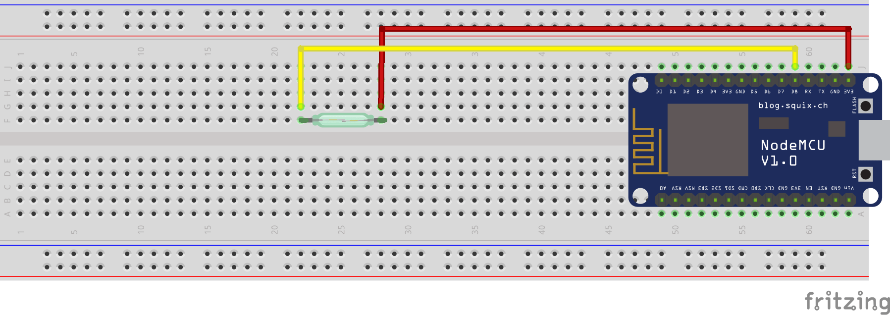
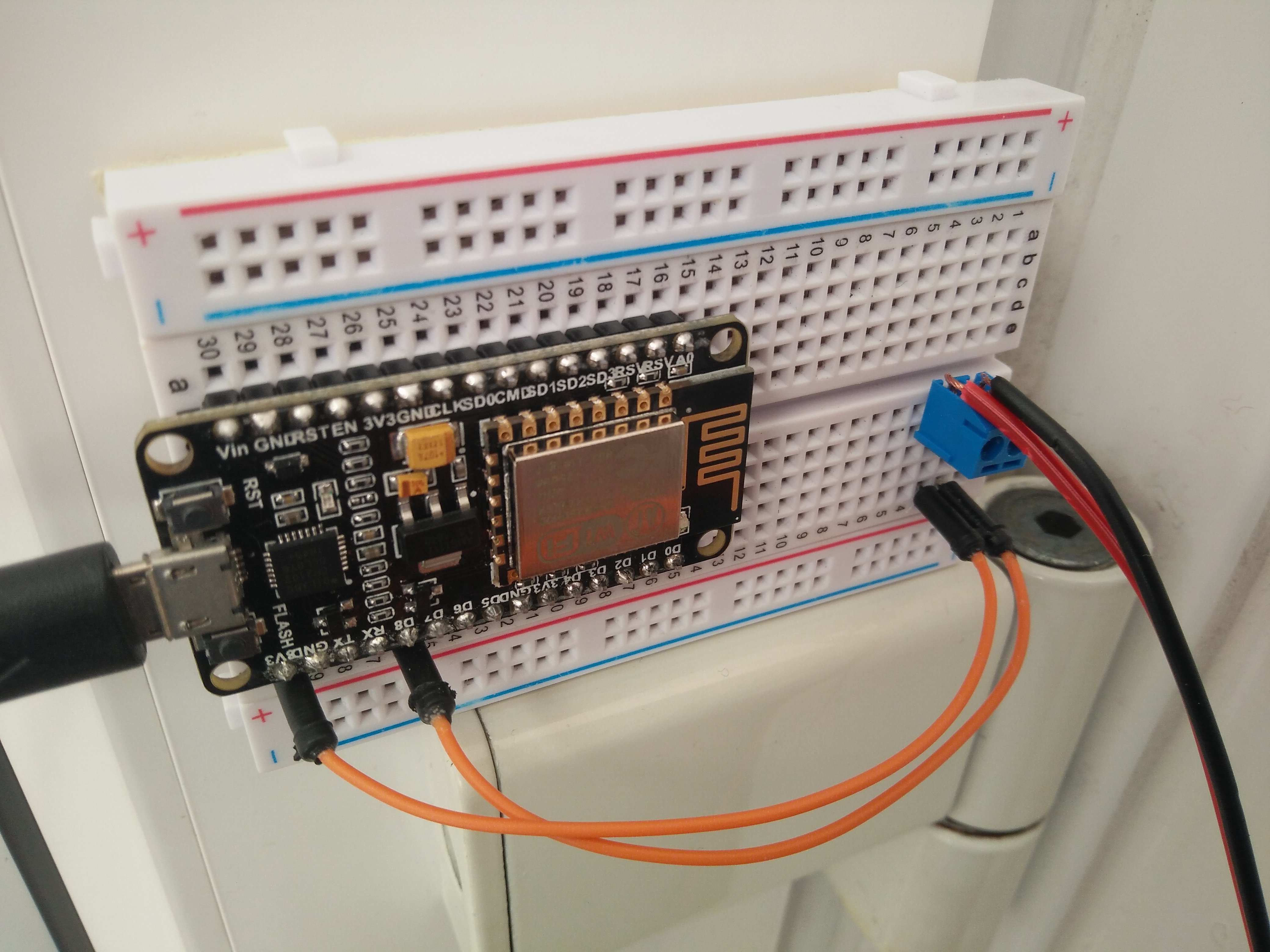
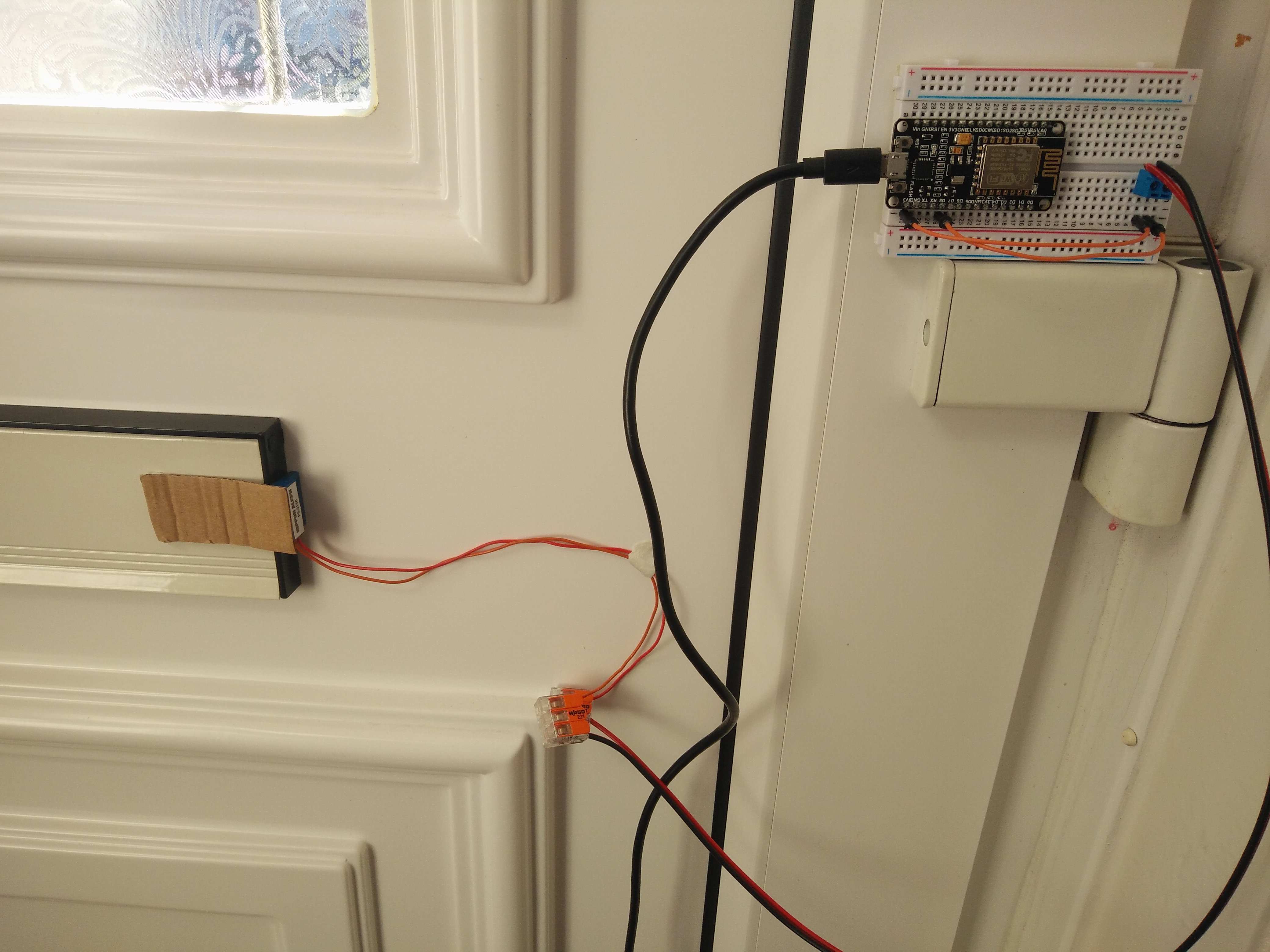
The hardware build for this project is incredibly simple. We only need a reed switch to connect to our NodeMCU board. So insert the NodeMCU board into the breadboard, and then insert the reed switch into the breadboard as per the diagram. Then using the jumper wires connect one side of the reed switch to D8 (Pin 15 in Mongoose OS) and the other side of the reed switch connects to 3V3.
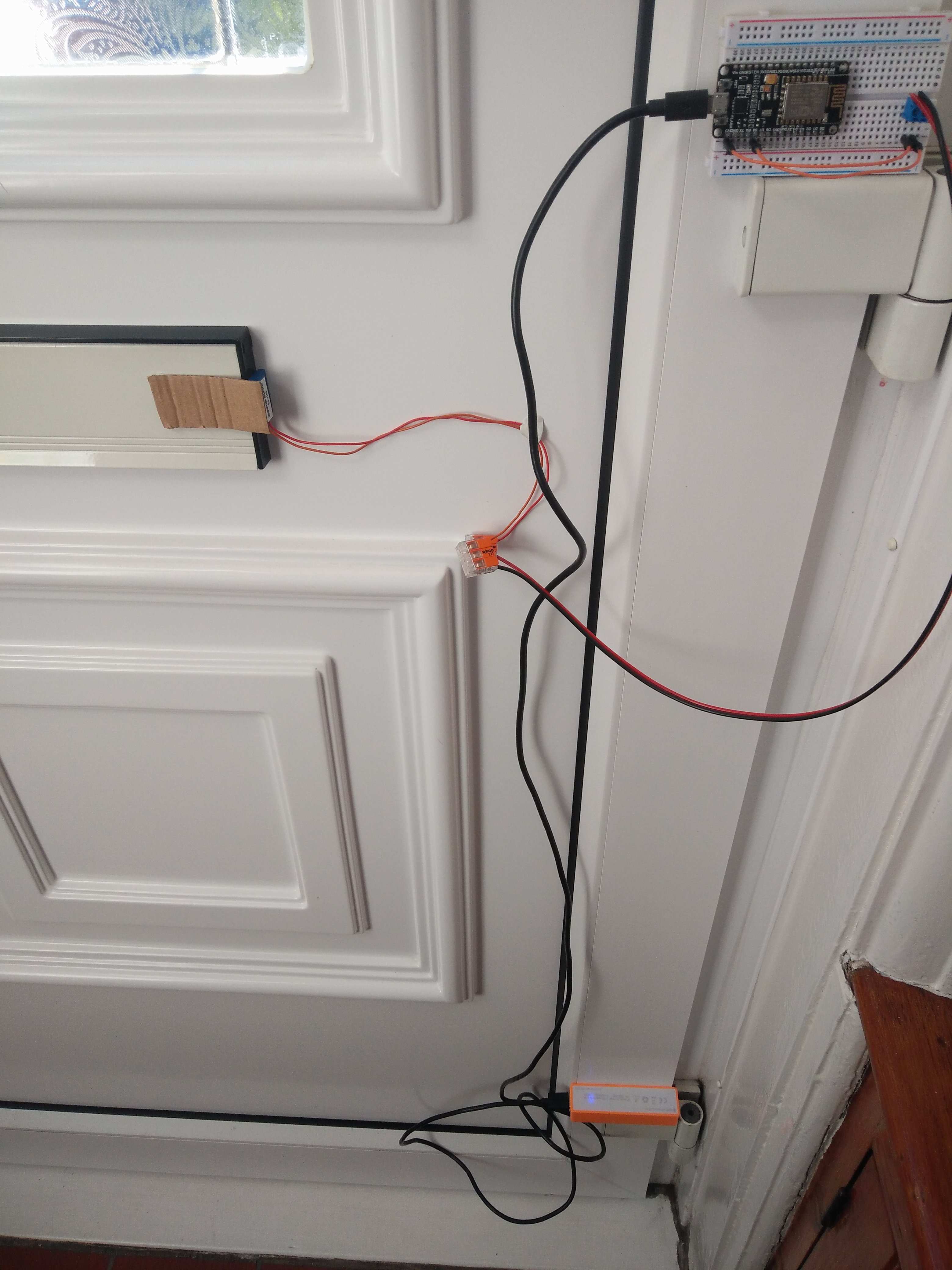
We also use Wago connectors to extend the wires of our reed switch. Wago connectors are quick and easy to use, we insert the wires and clamp them in place, no tools required!
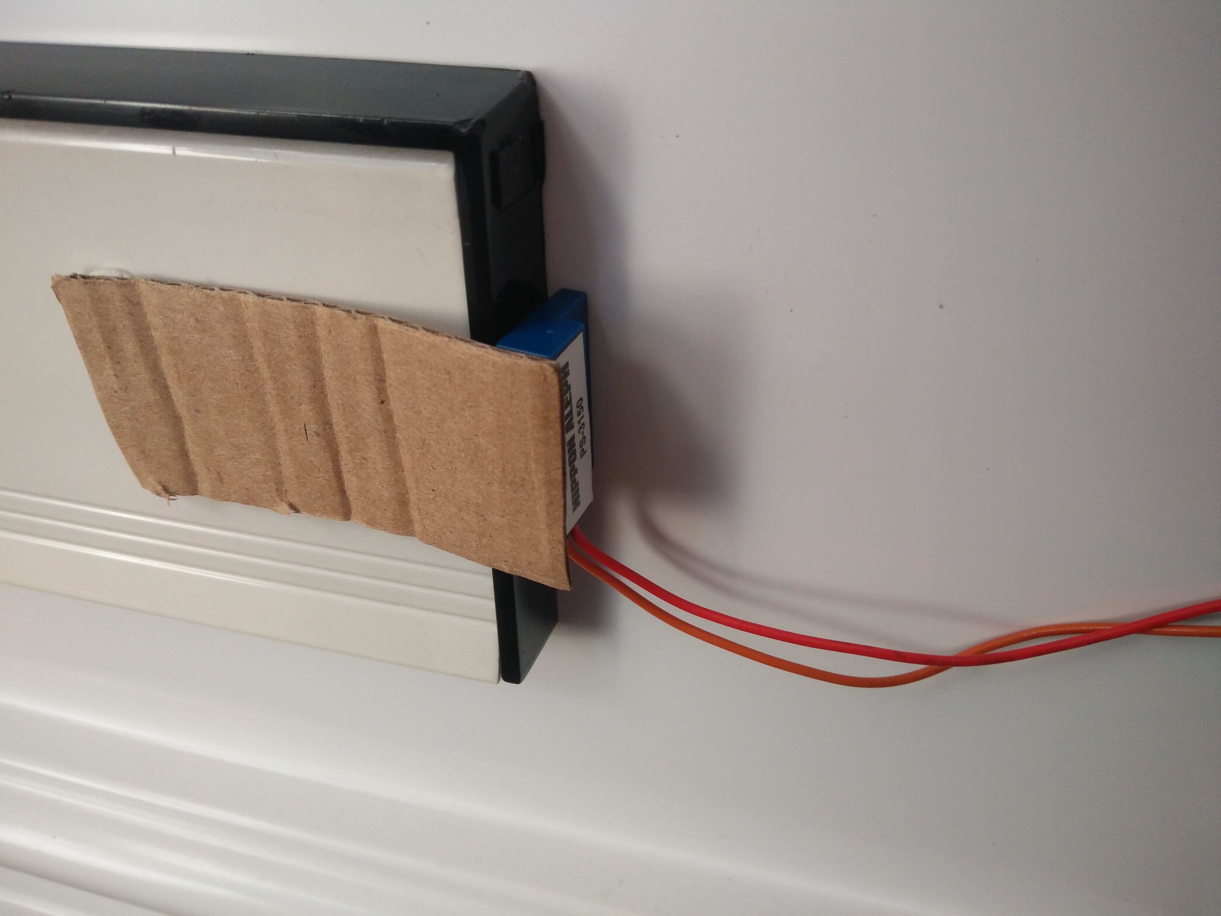
We also use a cardboard arm to attach the magnet and provide an element of flexibility to the arm, just in case the post person is forceful with our mail.
That’s it! Now on to the software setup.
Setting Up Mongoose OS
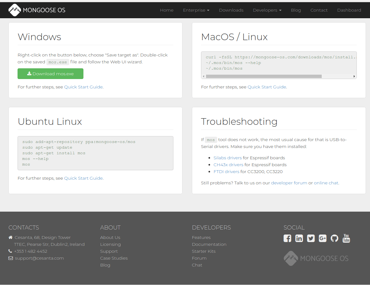
Insert a micro USB cable into the NodeMCU board and the other end to your computer. To use Mongoose OS on our machine we first need to install the software, and the instructions for which can be found on their website as https://mongoose-os.com/software.html we followed the guidance for Ubuntu Linux.
No matter which operating system you may use, running the “mos” command will launch a new browser window/tab for the Mongoose OS setup and our first task here is to make sure that our NodeMCU board has been correctly detected and has been assigned a device address. In the first drop down look for your NodeMCU board’s device address, for Linux/Mac this will be something like “/dev/ttyXYZ” and for Windows you should see a “COM” port. Select the correct address and press Select.
To flash the Mongoose OS to the NodeMCU we need to choose the platform which is “esp8266 4M or more flash), then select the “demo.js” app and click Flash. The flash process will take around 2 minutes and it will release control back to you once completed.
The final configuration step is to configure the WIFI to the settings used for your network.
Set up complete, let's take a look at the interface.
Getting to know Mongoose OS
Mongoose OS runs entirely in the web browser (there is a mos command line client, but the best experience is via the browser) and the layout of the window has a column to the left that provides quick access to the files, configuration and terminal for Mongoose OS on the NodeMCU. The second column adapts to show the contents/files/config as selected from the first column. The right-hand column contains the code saved to the board, here we can edit the code and create projects. At the bottom of the window we can see the device logs (bottom left) showing us the output of our code and the configuration steps taken on boot. To the bottom right we see the MOS tool logs that advise us on boot and flashing progress. To the very top right of the window we see the IP address of the board and device setup (for flashing the board and making changes to the WiFi.)
Setting Up MQTT
We’ve already covered what MQTT is in another blog post <> but a quick overview is that MQTT (Message Queue Telemetry Transport) operates a low bandwidth, low latency network over any internet connection. It works using a publish > broker > subscriber model. Publishers publish their data using “topics” which act as filters. The central broker receives the message and then subscribers who are also looking for messages of a certain topic connect to the broker and receive messages based on their preference. A real-world example of this is YouTube, content providers publish, YouTube brokers the content, and viewers subscribe to channels that interest them.
In this project, the Node MCU board is a publisher, and it will publish a message on the topic “postwatch” when the reed switch is triggered. But before we can set up our publisher, we first need to set up the broker to which our publisher will send messages to.
Create a quick broker
The fastest way to create a broker is to use a Raspberry Pi or Linux machine and install the Mosquitto software.
In a terminal type the following.
sudo apt install mosquitto mosquitto-clients
Then to ensure the MQTT broker is running type
sudo service mosquitto start
Make a note of your broker IP address as both the publisher (our Node MCU) and the subscriber (any device we wish) will need to know where their broker is.
hostname -a
Setting up the publisher
Now we can set up the publisher element of the Node MCU part of the project. Click on the Device Config menu option and in the device configuration screen change the MQTT settings so that the MQTT server is the IP address of the broker, followed by :1883. Also, make sure that the Enable MQTT button is ticked. Then click on the Save configuration button.
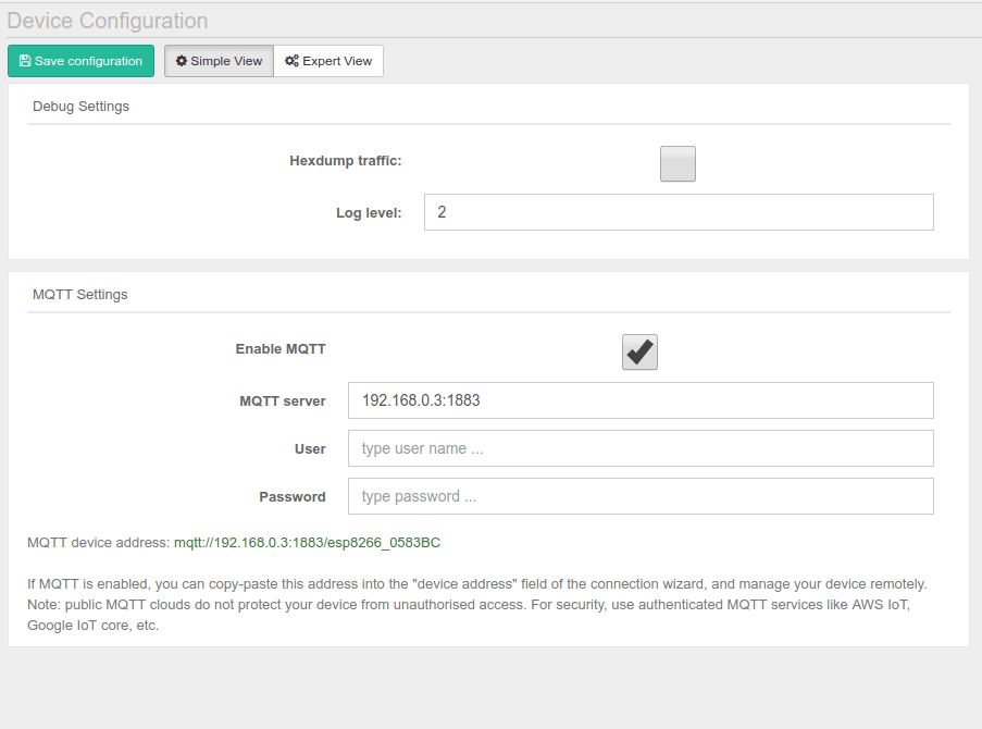
That’s it – now our Node MCU board knows where to send the messages, so all we need to do is write the code.
Receiving the messages
So how would you like to be notified of the post arriving? Well here are two ways that we used
Android App to receive messages
For simple debugging and real-time messages we use the MQTT Client app for Android (https://play.google.com/store/apps/details?id=in.dc297.mqttclpro). As it proves to be an easy tool for use when needing to confirm that messages are being published and that we can publish messages to the network.

Ubuntu hack for pop-ups
If you would like to receive messages on your Linux device, then we found that a simple method to have the messages appear was using the notify-send application to create notifications that show on the desktop. We have also created a one-line bash script that will achieve this. This command will subscribe to the topic “postwatch” using the broker IP address (change this to your own), then the output of that command is piped into a variable called OUTPUT and this is then used in the notify-send command to create the notifications.
mosquitto_sub -t postwatch -h 192.168.0.3 | while read OUTPUT; do notify-send "$OUTPUT"; done
Coding the postwatch app
Our app has one goal, to tell us that the post has arrived, and we get a lot of posts! Those small packages from Shenzhen soon mount up and we almost always forget what we ordered four weeks ago.
To edit the code in this project we first need to be in the Device Files sub menu and from there, via the Device File Manager we need to edit the “init.js” file. Click on the file and you will see the contents of the file appear on the screen. Select all of the code in the file and then delete it.
We start our code by loading two libraries; the first enables MQTT to be used with the project. Then we load the GPIO library so that we can use the reed switch to trigger the code.
load('api_mqtt.js');

load('api_gpio.js');
We next create three variables. The first specifies the GPIO pin that we are using, 15. The second variable is the topic for our MQTT connection. Lastly, we use msg to specify the message that will be sent when the application is triggered.
let pin = 15, topic = 'postwatch';let msg = 'Letterbox Open';
The next line of code is a long one, but it creates a function that handles button presses. Our pin, GPIO15 uses an internal pull-up, then we set a debounce time of 2000 milliseconds to enable the post person to successfully post our item and only trigger the sensor once.
GPIO.set_button_handler(pin, GPIO.PULL_UP, GPIO.INT_EDGE_NEG, 2000, function() {
Then we move on to create the steps taken when the reed sensor has been triggered. We create another variable called “res” and in this we publish the message to MQTT, using the correct topic and converting the data to a message. For debug purposes we print the success or failure of the published message to the Device Log (bottom left of the screen) before we close the function and end the code for the project.
let res = MQTT.pub(topic, JSON.stringify(msg), 1);print('Published:', res ? 'yes' : 'no');}, null);
To write the code to our NodeMCU board all we need to do is click on “Save + Reboot”. Give it a few moments and now take a magnet place it against the reed switch and then remove it to trigger the board to send a message on the MQTT topic “postwatch” to inform us that the post has arrived! We can see the message appear in the Device Log, informing us of a message, and depending on how we chose to receive a message, we will see the message appear on that device.
So there we have it, an automated postwatch application that informs us when new post arrives via a message on MQTT. To expand on this project, you could use a public MQTT broker such as http://www.mqtt-dashboard.com/ so that messages from your postwatch application can be sent across the Internet. Obviously never send sensitive data over the open Internet but this could be an interesting option to create a project that reaches far far away!








Leave your feedback...