

Wio E5 Powered Solar Environmental Node With Qubitro

Made by pradeeplogu0 / Communication / Environmental Sensing / Weather
About the project
Will guide you to build a Solar Powered Environmental Node with Wio E5, Xiao nRF52840 Sense, and BME680.
Project info
Difficulty: Moderate
Platforms: Seeed Studio, Nordic Semiconductor
Estimated time: 1 hour
License: GNU General Public License, version 3 or later (GPL3+)
Items used in this project
Hardware components

Story
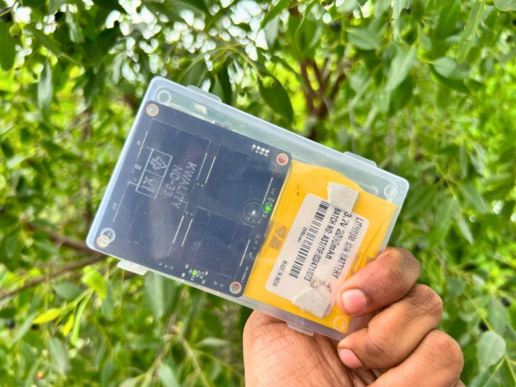
In this project, we will design and develop a self-sustaining, solar-powered environmental sensor node equipped with the advanced BME680 sensor. This versatile sensor is capable of accurately measuring key ecological parameters such as temperature, humidity, barometric pressure, and volatile organic compounds (VOC) to assess air quality Powered by a solar panel and optimized for low-power consumption, this system ensures long-term functionality even in remote, off-grid locations.
To transmit the collected data, the node will employ LoRa (long-range) communication, a highly efficient wireless technology known for its ability to cover vast distances with minimal power. This makes it particularly suitable for applications where traditional connectivity options are either unavailable or unreliable, such as in rural areas, forests, or disaster-prone zones.
The node will continuously collect environmental data and send it to a central gateway, which can be further analyzed, stored, or visualized in real time. This project holds immense potential for various use cases, including remote climate monitoring, agricultural management, and air quality assessments in hard-to-reach areas. With its sustainable design and robust communication capabilities, this solar-powered sensor node is an innovative solution for advancing environmental monitoring in challenging locations.

Components Needed:
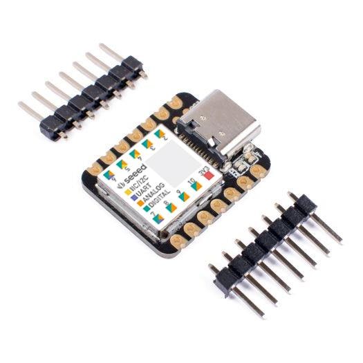
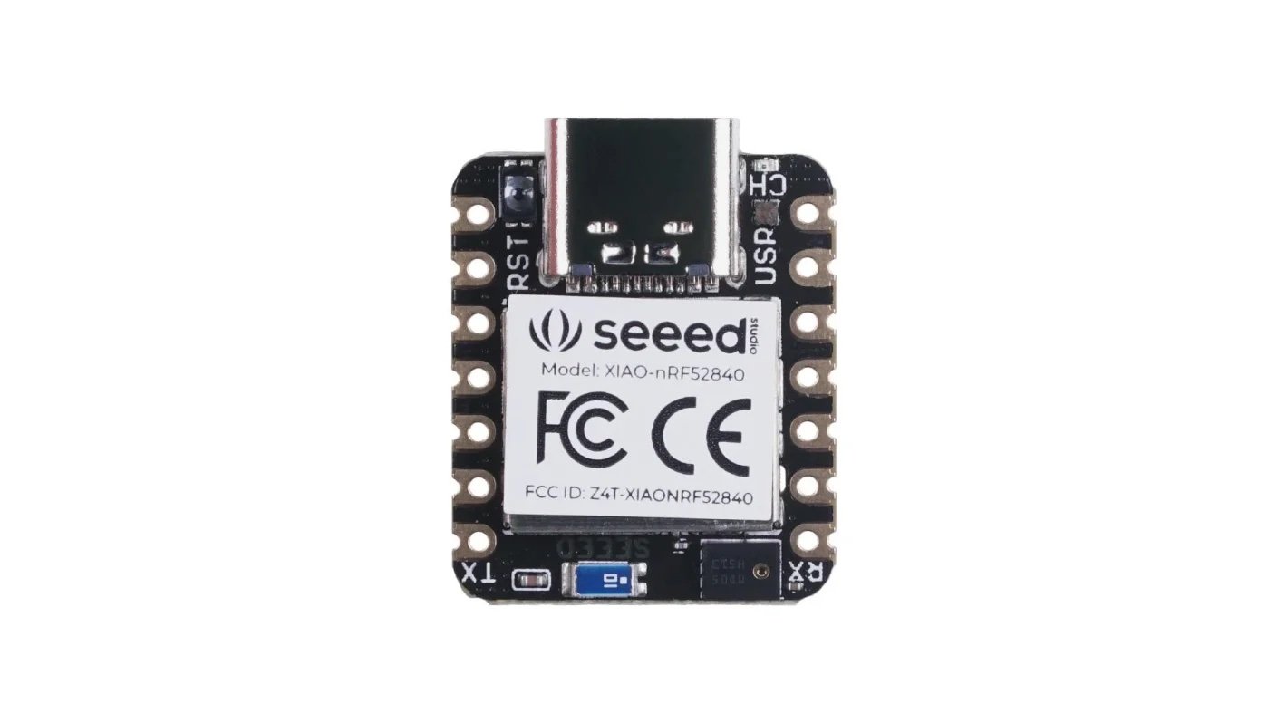
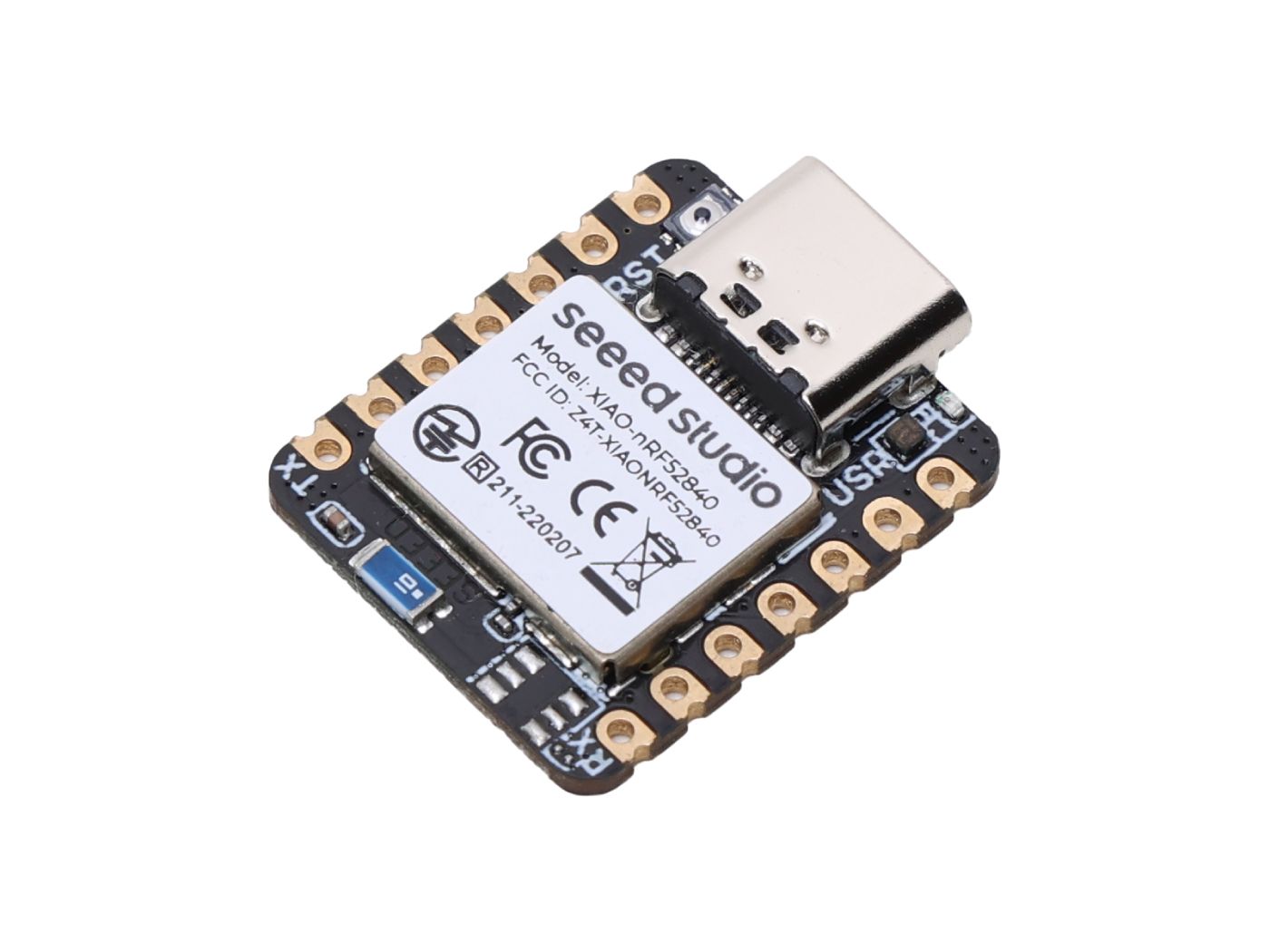
- Microcontroller: Xiao nRF52840 Sense.
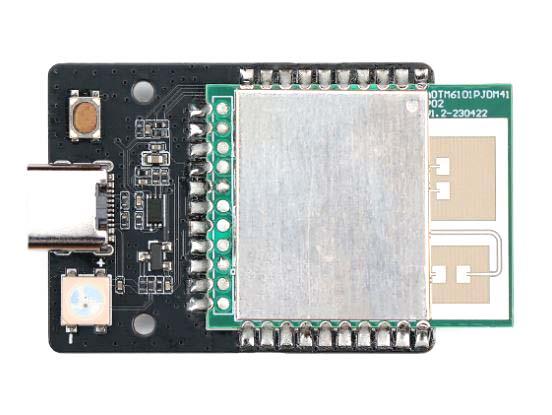
- LoRa Module: Wio E5.
- BME680 Sensor: For measuring environmental parameters.
- Solar Panel: 5V or higher, depending on your power requirements.
- Battery: LiPo battery to store solar energy.
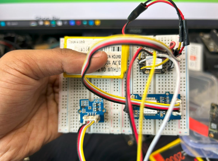
Step 1: Circuit Diagram :
I have implemented this project with a breadboard using Wio E5, Xiao ESP32S3 Grove Sunlight sensor, and a LiPo battery.
Xiao nRF52840 Sense:
- Microcontroller: Based on the nRF52840 SoC, it features Bluetooth 5.0, NFC, and various sensors (e.g., IMU, microphone).
- Size: Ultra-small form factor, making it ideal for compact designs.
- Features: Low power consumption, multiple I/O options, and built-in sensors for additional data collection.
LoRa Wio E5:
- LoRa Module: Integrates the STM32WLE5JC, which combines an MCU and LoRa transceiver.
- Frequency: Supports global LoRaWAN frequencies.
- Features: Low power consumption, long-range communication, and easy integration with LoRaWAN networks.
BME680 Sensor:
- Environmental Sensor: Measures temperature, humidity, pressure, and gas levels.
- Interface: I2C or SPI communication.
- Features: High accuracy, low power consumption, and compact size.
A breadboard is a reusable platform used for prototyping electronic circuits without soldering. It allows for quick and easy assembly and modification of circuits. But we can use this as a direct application. So, I planned to build a PCB with all these components.
Here is the schematic of the project.
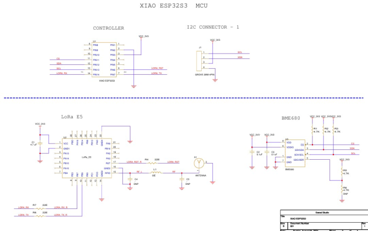
In this schematic, I have used three different components. The first one is Xiao nRF52840 Sense , then LoRa Wio E5, and BME680
Here is the final 3D view of my design.
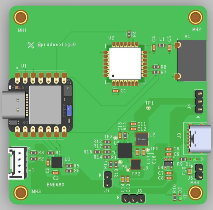
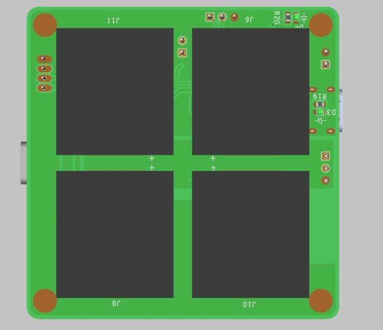
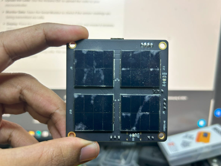
I have added a solar panel in the backside of the PCB. â€Â‹ This allows us to directly use this outdoors without any power issues. Also, I have added the grove port to add additional sensors.
Step 2: Power-Up PCBA:
Instead of using wires, you can create your customized PCBs with Seeed Fusion PCBA services, and they're also offering free prototype and functional testing on your first sample.

Discover more here! Invigorate your Inspiration for IoT with Wio-E5 and FREE Seeed Fusion PCBA Prototypes https://seeedstudio.com/blog/2021/10/21/invigorate-your-inspiration-for-iot-with-lora-e5-and-free-seeed-fusion-pcba-prototypes/…

Unleash the Magic Power of IoT with the New Wio-WM1110 and Get FREE Seeed Fusion PCBA Services https://seeedstudio.com/blog/2023/06/0
Here you can find out more info on the Wio E5
Step 3: Board Bring-up:
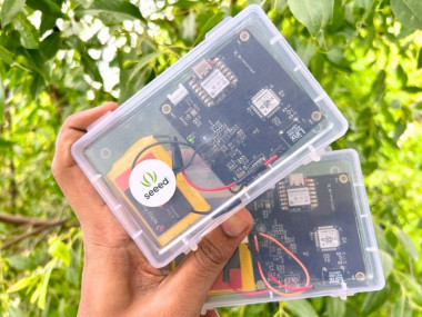
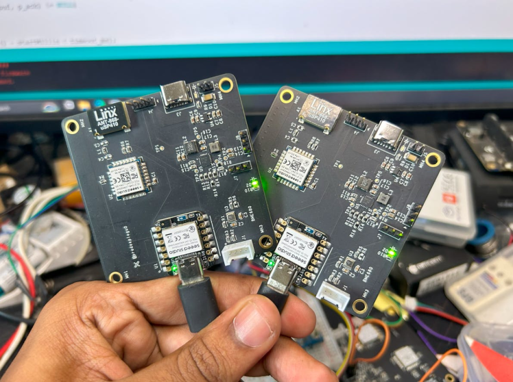
Once I got my boards, I just verified that is there any visible defects.
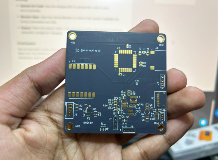
Backside view
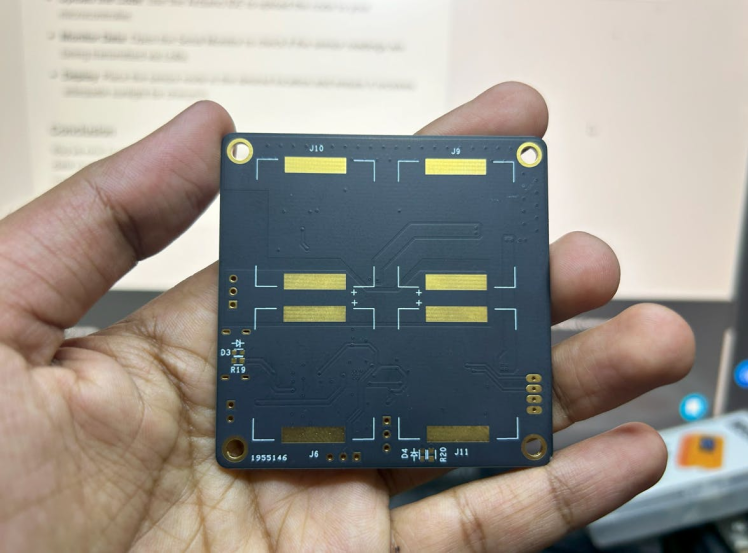
Next, let's check the assembled PCBs.
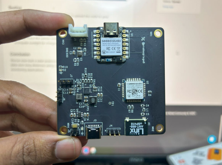
Backside view
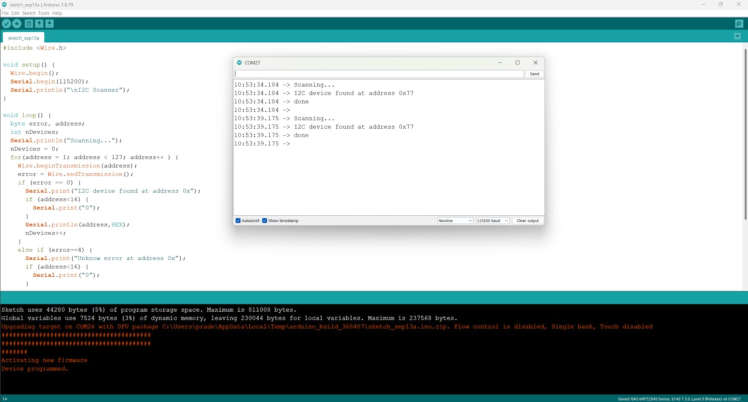
Then, we need to check for the sensor connections. Here is a simple sketch that can check the I2C sensors.
#include <Wire.h>

void setup() {
  Wire.begin();
  Serial.begin(115200);
  Serial.println("nI2C Scanner");
}

void loop() {
  byte error, address;
  int nDevices;
  Serial.println("Scanning...");
  nDevices = 0;
  for(address = 1; address < 127; address++ ) {
    Wire.beginTransmission(address);
    error = Wire.endTransmission();
    if (error == 0) {
      Serial.print("I2C device found at address 0x");
      if (address<16) {
        Serial.print("0");
      }
      Serial.println(address,HEX);
      nDevices++;
    }
    else if (error==4) {
      Serial.print("Unknow error at address 0x");
      if (address<16) {
        Serial.print("0");
      }
      Serial.println(address,HEX);
    }
  }
  if (nDevices == 0) {
    Serial.println("No I2C devices foundn");
  }
  else {
    Serial.println("donen");
  }
  delay(5000);
}
Luckily there are no defects in my design, and my BME680 was detected in the I2C connection.
Next, let's implement the BME680 and Wio E5.
Step 4: BME680 Setup
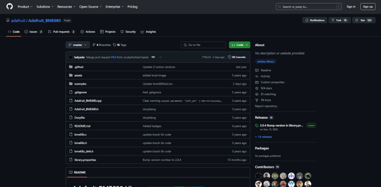
Install Libraries: Install the BME680 library from the Arduino Library Manager.
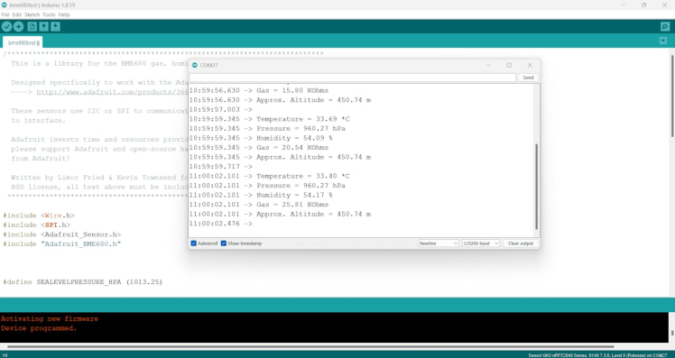
Code Example: Here is the simple sketch to get environmental data from the BME680.
#include <Wire.h>
#include <Adafruit_Sensor.h>
#include <Adafruit_BME680.h>

#define SEALEVELPRESSURE_HPA (1013.25)

Adafruit_BME680 bme; // Create an instance of the sensor

void setup() {
  Serial.begin(9600);
  if (!bme.begin()) {
    Serial.println("Could not find a valid BME680 sensor, check wiring!");
    while (1);
  }


  // Set up BME680
  bme.setTemperatureOversampling(BME680_OS_8X);
  bme.setHumidityOversampling(BME680_OS_2X);
  bme.setPressureOversampling(BME680_OS_4X);
  bme.setIIRFilterSize(BME680_FILTER_SIZE_3);
  bme.setGasHeater(320, 150); // 320*C for 150 ms
}

void loop() {
  // Perform a reading
  if (!bme.performReading()) {
    Serial.println("Failed to perform reading :(");
    return;
  }

  // Print data to Serial Monitor
  Serial.print("Temperature = ");
  Serial.print(bme.temperature);
  Serial.println(" *C");

  Serial.print("Humidity = ");
  Serial.print(bme.humidity);
  Serial.println(" %");

  Serial.print("Pressure = ");
  Serial.print(bme.pressure / 100.0);
  Serial.println(" hPa");

  Serial.print("Gas = ");
  Serial.print(bme.gas_resistance / 1000.0);
  Serial.println(" KOhms");

  delay(2000); // Wait for 2 seconds before next reading
}
Here is the serial terminal response for the BME680 example sketch.
Step 5: Wio E5 Setup
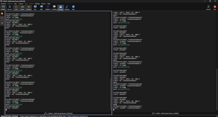
Next, let's implement the Wio E5. Here is the simple P2P sketch that can send and receive data.
Transmitter Node:
#include <Arduino.h>
#include <Adafruit_TinyUSB.h>
//#define NODE_SLAVE //Enable for Slave //Comment for Master
static char recv_buf[512];
static bool is_exist = false;
static int at_send_check_response(char *p_ack, int timeout_ms, char*p_cmd, ...)
{
  int ch = 0;
  int index = 0;
  int startMillis = 0;
  va_list args;
  memset(recv_buf, 0, sizeof(recv_buf));
  va_start(args, p_cmd);
  Serial1.printf(p_cmd, args);
  Serial.printf(p_cmd, args);
  va_end(args);
  delay(200);
  startMillis = millis();
  if (p_ack == NULL)
  {
    return 0;
  }
  do
  {
    while (Serial1.available() > 0)
    {
      ch = Serial1.read();
      recv_buf[index++] = ch;
      Serial.print((char)ch);
      delay(2);
    }
    if (strstr(recv_buf, p_ack) != NULL)
    {
      return 1;
    }
  } while (millis() - startMillis < timeout_ms);
  return 0;
}
static int recv_prase(void)
{
  char ch;
  int index = 0;
  memset(recv_buf, 0, sizeof(recv_buf));
  while (Serial1.available() > 0)
  {
    ch = Serial1.read();
    recv_buf[index++] = ch;
    Serial.print((char)ch);
    delay(2);
  }
  if (index)
  {
    char *p_start = NULL;
    char data[32] = {
      0,
    };
    int rssi = 0;
    int snr = 0;
    p_start = strstr(recv_buf, "+TEST: RX "5345454544");
    if (p_start)
    {
      p_start = strstr(recv_buf, "5345454544");
      if (p_start && (1 == sscanf(p_start, "5345454544%s", data)))
      {
        data[4] = 0;
        Serial.print(data);
        Serial.print("rn");
      }
      p_start = strstr(recv_buf, "RSSI:");
      if (p_start && (1 == sscanf(p_start, "RSSI:%d,", &rssi)))
      {
      }
      p_start = strstr(recv_buf, "SNR:");
      if (p_start && (1 == sscanf(p_start, "SNR:%d", &snr)))
      {
      }
      return 1;
    }
  }
  return 0;
}
static int node_recv(uint32_t timeout_ms)
{
  at_send_check_response("+TEST: RXLRPKT", 1000, "AT+TEST=RXLRPKTrn");
  int startMillis = millis();
  do
  {
    if (recv_prase())
    {
      return 1;
    }
  } while (millis() - startMillis < timeout_ms);
  return 0;
}
static int node_send(void)
{
  static uint16_t count = 0;
  int ret = 0;
  char data[32];
  char cmd[128];
  memset(data, 0, sizeof(data));
  sprintf(data, "%04X", count);
  sprintf(cmd, "AT+TEST=TXLRPKT,"5345454544%s"rn", data);
  ret = at_send_check_response("TX DONE", 2000, cmd);
  if (ret == 1)
  {
    count++;
    Serial.print("Sent successfully!rn");
  }
  else
  {
    Serial.print("Send failed!rn");
  }
  return ret;
}
static void node_recv_then_send(uint32_t timeout)
{
  int ret = 0;
  ret = node_recv(timeout);
  delay(100);
  if (!ret)
  {
    Serial.print("rn");
    return;
  }
  node_send();
  Serial.print("rn");
}
static void node_send_then_recv(uint32_t timeout)
{
  int ret = 0;
  ret = node_send();
  if (!ret)
  {
    Serial.print("rn");
    return;
  }
  if (!node_recv(timeout))
  {
    Serial.print("recv timeout!rn");
  }
  Serial.print("rn");
}
void setup(void)
{
  pinMode(LED_BUILTIN, OUTPUT);
  pinMode(LED_GREEN, OUTPUT);
  Serial.begin(115200);
  // while (!Serial);
  Serial1.begin(9600);
  Serial.print("ping pong communication!rn");
  if (at_send_check_response("+AT: OK", 100, "ATrn"))
  {
    is_exist = true;
    at_send_check_response("+MODE: TEST", 1000, "AT+MODE=TESTrn");
    at_send_check_response("+TEST: RFCFG", 1000, "AT+TEST=RFCFG,866,SF12,125,12,15,14,ON,OFF,OFFrn");
    delay(200);
  }
  else
  {
    is_exist = false;
    Serial.print("No E5 module found.rn");
  }
}
void loop(void)
{

  digitalWrite(LED_BUILTIN, LOW);
  digitalWrite(LED_GREEN, HIGH);
  if (is_exist)
  {
# ifdef NODE_SLAVE
    node_recv_then_send(2000);
# else
    node_send_then_recv(2000);
    delay(3000);
# endif
  }
  digitalWrite(LED_BUILTIN, HIGH);
  digitalWrite(LED_GREEN, LOW);
}
Receiver Node:
#include <Arduino.h>
#include <Adafruit_TinyUSB.h>
#define NODE_SLAVE //Enable for Slave //Comment for Master
static char recv_buf[512];
static bool is_exist = false;
static int at_send_check_response(char *p_ack, int timeout_ms, char*p_cmd, ...)
{
  int ch = 0;
  int index = 0;
  int startMillis = 0;
  va_list args;
  memset(recv_buf, 0, sizeof(recv_buf));
  va_start(args, p_cmd);
  Serial1.printf(p_cmd, args);
  Serial.printf(p_cmd, args);
  va_end(args);
  delay(200);
  startMillis = millis();
  if (p_ack == NULL)
  {
    return 0;
  }
  do
  {
    while (Serial1.available() > 0)
    {
      ch = Serial1.read();
      recv_buf[index++] = ch;
      Serial.print((char)ch);
      delay(2);
    }
    if (strstr(recv_buf, p_ack) != NULL)
    {
      return 1;
    }
  } while (millis() - startMillis < timeout_ms);
  return 0;
}
static int recv_prase(void)
{
  char ch;
  int index = 0;
  memset(recv_buf, 0, sizeof(recv_buf));
  while (Serial1.available() > 0)
  {
    ch = Serial1.read();
    recv_buf[index++] = ch;
    Serial.print((char)ch);
    delay(2);
  }
  if (index)
  {
    char *p_start = NULL;
    char data[32] = {
      0,
    };
    int rssi = 0;
    int snr = 0;
    p_start = strstr(recv_buf, "+TEST: RX "5345454544");
    if (p_start)
    {
      p_start = strstr(recv_buf, "5345454544");
      if (p_start && (1 == sscanf(p_start, "5345454544%s", data)))
      {
        data[4] = 0;
        Serial.print(data);
        Serial.print("rn");
      }
      p_start = strstr(recv_buf, "RSSI:");
      if (p_start && (1 == sscanf(p_start, "RSSI:%d,", &rssi)))
      {
      }
      p_start = strstr(recv_buf, "SNR:");
      if (p_start && (1 == sscanf(p_start, "SNR:%d", &snr)))
      {
      }
      return 1;
    }
  }
  return 0;
}
static int node_recv(uint32_t timeout_ms)
{
  at_send_check_response("+TEST: RXLRPKT", 1000, "AT+TEST=RXLRPKTrn");
  int startMillis = millis();
  do
  {
    if (recv_prase())
    {
      return 1;
    }
  } while (millis() - startMillis < timeout_ms);
  return 0;
}
static int node_send(void)
{
  static uint16_t count = 0;
  int ret = 0;
  char data[32];
  char cmd[128];
  memset(data, 0, sizeof(data));
  sprintf(data, "%04X", count);
  sprintf(cmd, "AT+TEST=TXLRPKT,"5345454544%s"rn", data);
  ret = at_send_check_response("TX DONE", 2000, cmd);
  if (ret == 1)
  {
    count++;
    Serial.print("Sent successfully!rn");
  }
  else
  {
    Serial.print("Send failed!rn");
  }
  return ret;
}
static void node_recv_then_send(uint32_t timeout)
{
  int ret = 0;
  ret = node_recv(timeout);
  delay(100);
  if (!ret)
  {
    Serial.print("rn");
    return;
  }
  node_send();
  Serial.print("rn");
}
static void node_send_then_recv(uint32_t timeout)
{
  int ret = 0;
  ret = node_send();
  if (!ret)
  {
    Serial.print("rn");
    return;
  }
  if (!node_recv(timeout))
  {
    Serial.print("recv timeout!rn");
  }
  Serial.print("rn");
}
void setup(void)
{
  pinMode(LED_BUILTIN, OUTPUT);
  pinMode(LED_GREEN, OUTPUT);
  Serial.begin(115200);
  // while (!Serial);
  Serial1.begin(9600);
  Serial.print("ping pong communication!rn");
  if (at_send_check_response("+AT: OK", 100, "ATrn"))
  {
    is_exist = true;
    at_send_check_response("+MODE: TEST", 1000, "AT+MODE=TESTrn");
    at_send_check_response("+TEST: RFCFG", 1000, "AT+TEST=RFCFG,866,SF12,125,12,15,14,ON,OFF,OFFrn");
    delay(200);
  }
  else
  {
    is_exist = false;
    Serial.print("No E5 module found.rn");
  }
}
void loop(void)
{

  digitalWrite(LED_BUILTIN, LOW);
  digitalWrite(LED_GREEN, HIGH);
  if (is_exist)
  {
# ifdef NODE_SLAVE
    node_recv_then_send(2000);
# else
    node_send_then_recv(2000);
    delay(3000);
# endif
  }
  digitalWrite(LED_BUILTIN, HIGH);
  digitalWrite(LED_GREEN, LOW);
}
Serial Terminal Response:
Step 6: Let's Implement the Solar Env Node:
We have already implemented the BME680 and Wio E5. The next thing is to transmit the BME680 data to Things Network via Wio E5. Here is the Arduino sketch that can transmit the BME680 data to TTN.
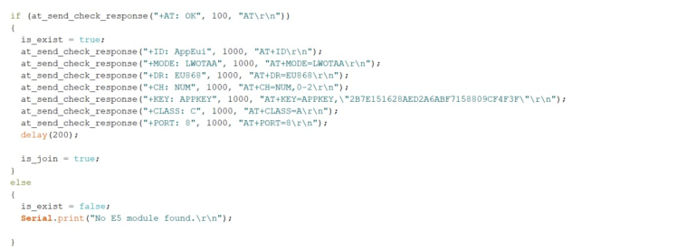
Here is the frequency band and the app id.
#include <Wire.h>
#include <Arduino.h>
#include <Adafruit_Sensor.h>
#include "Adafruit_BME680.h"
#include <Adafruit_TinyUSB.h>

static char recv_buf[512];
static bool is_exist = false;
static bool is_join = false;
static int led = 0;

#define SEALEVELPRESSURE_HPA (1013.25)

static int at_send_check_response(char *p_ack, int timeout_ms, char*p_cmd, ...)
{
  int ch;
  int num = 0;
  int index = 0;
  int startMillis = 0;
  va_list args;
  memset(recv_buf, 0, sizeof(recv_buf));
  va_start(args, p_cmd);
  Serial1.printf(p_cmd, args);
  Serial.printf(p_cmd, args);
  va_end(args);
  delay(200);
  startMillis = millis();

  if (p_ack == NULL)
  {
    return 0;
  }

  do
  {
    while (Serial1.available() > 0)
    {
      ch = Serial1.read();
      recv_buf[index++] = ch;
      Serial.print((char)ch);
      delay(2);
    }

    if (strstr(recv_buf, p_ack) != NULL)
    {
      return 1;
    }

  } while (millis() - startMillis < timeout_ms);
  return 0;
}

static void recv_prase(char *p_msg)
{
  if (p_msg == NULL)
  {
    return;
  }
  char*p_start = NULL;
  int data = 0;
  int rssi = 0;
  int snr = 0;

  p_start = strstr(p_msg, "RX");
  if (p_start && (1 == sscanf(p_start, "RX: "%d"rn", &data)))
  {
    Serial.println(data);
    if (led)
    {
      digitalWrite(LED_BUILTIN, LOW);
    }
    else
    {
      digitalWrite(LED_BUILTIN, HIGH);
    }
  }

  p_start = strstr(p_msg, "RSSI");
}

Adafruit_BME680 bme; // I2C

void setup() {
  pinMode(LED_BUILTIN, OUTPUT);
  pinMode(LED_GREEN, OUTPUT);
  Serial.begin(115200);

  if (!bme.begin()) {
    Serial.println(F("Could not find a valid BME680 sensor, check wiring!"));
    while (1);
  }

  bme.setTemperatureOversampling(BME680_OS_8X);
  bme.setHumidityOversampling(BME680_OS_2X);
  bme.setPressureOversampling(BME680_OS_4X);
  bme.setIIRFilterSize(BME680_FILTER_SIZE_3);
  bme.setGasHeater(320, 150);

  Serial1.begin(9600);
  Serial.print("E5 LORAWAN TESTrn");


  if (at_send_check_response("+AT: OK", 100, "ATrn"))
  {
    is_exist = true;
    at_send_check_response("+ID: AppEui", 1000, "AT+IDrn");
    at_send_check_response("+MODE: LWOTAA", 1000, "AT+MODE=LWOTAArn");
    at_send_check_response("+DR: EU868", 1000, "AT+DR=EU868rn");
    at_send_check_response("+CH: NUM", 1000, "AT+CH=NUM,0-2rn");
    at_send_check_response("+KEY: APPKEY", 1000, "AT+KEY=APPKEY,"2B7E151628AED2A6ABF7158809CF4F3F"rn");
    at_send_check_response("+CLASS: C", 1000, "AT+CLASS=Arn");
    at_send_check_response("+PORT: 8", 1000, "AT+PORT=8rn");
    delay(200);

    is_join = true;
  }
  else
  {
    is_exist = false;
    Serial.print("No E5 module found.rn");

  }

}

void loop() {

  digitalWrite(LED_BUILTIN, LOW);
  digitalWrite(LED_GREEN, HIGH);

  delay(1000);

  digitalWrite(LED_BUILTIN, HIGH);
  digitalWrite(LED_GREEN, LOW);


  Serial.print(F("Temperature = "));
  Serial.print(bme.temperature);
  Serial.println(F(" *C"));

  Serial.print(F("Pressure = "));
  Serial.print(bme.pressure / 100.0);
  int a = bme.pressure / 100.0;
  Serial.println(F(" hPa"));

  Serial.print(F("Humidity = "));
  Serial.print(bme.humidity);
  Serial.println(F(" %"));

  Serial.print(F("Gas = "));
  Serial.print(bme.gas_resistance / 1000.0);
  int b = bme.gas_resistance / 1000.0;
  Serial.println(F(" KOhms"));

  Serial.print(F("Approx. Altitude = "));
  Serial.print(bme.readAltitude(SEALEVELPRESSURE_HPA));
  int c = bme.readAltitude(SEALEVELPRESSURE_HPA);
  Serial.println(F(" m"));
  digitalWrite(LED_BUILTIN, LOW);
  digitalWrite(LED_GREEN, HIGH);

  delay(1000);
  digitalWrite(LED_BUILTIN, HIGH);
  digitalWrite(LED_GREEN, LOW);

  delay(1000);

  if (is_exist)
  {
    digitalWrite(LED_BUILTIN, LOW);
    digitalWrite(LED_GREEN, HIGH);

    delay(1000);

    digitalWrite(LED_BUILTIN, HIGH);
    digitalWrite(LED_GREEN, LOW);

    int ret = 0;
    if (is_join)
    {

      ret = at_send_check_response("+JOIN: Network joined", 12000, "AT+JOINrn");
      if (ret)
      {
        is_join = false;
      }
      else
      {
        at_send_check_response("+ID: AppEui", 1000, "AT+IDrn");
        Serial.print("JOIN failed!rnrn");
        delay(5000);
      }
    }
    else
    {
      char cmd[128];
      sprintf(cmd, "AT+CMSGHEX="%04X%04X%04X%04X%04X"rn", (int)bme.temperature, (int)bme.humidity, (int)a, (int)b, (int)c);
      ret = at_send_check_response("Done", 5000, cmd);

      digitalWrite(LED_BUILTIN, LOW);
      digitalWrite(LED_GREEN, HIGH);

      delay(1000);

      digitalWrite(LED_BUILTIN, HIGH);
      digitalWrite(LED_GREEN, LOW);
      if (ret)
      {
        recv_prase(recv_buf);
      }
      else
      {
        Serial.print("Send failed!rnrn");
      }
      delay(5000);
    }
  }
  else
  {
    delay(1000);
  }

  Serial.println();
  digitalWrite(LED_BUILTIN, HIGH);
  digitalWrite(LED_GREEN, LOW);
  delay(1000);
}
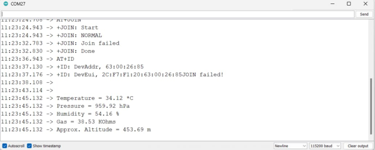
This above code snippet can send 5 different data to the TTN. This serial terminal response shows the TTN credentials. Next, we have to add this device to the TTN console application.
Step 7: TTN setup for the Solar Env Node:
Navigate to the TTN console. Create a new application and an end device.
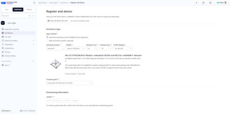
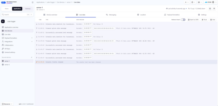
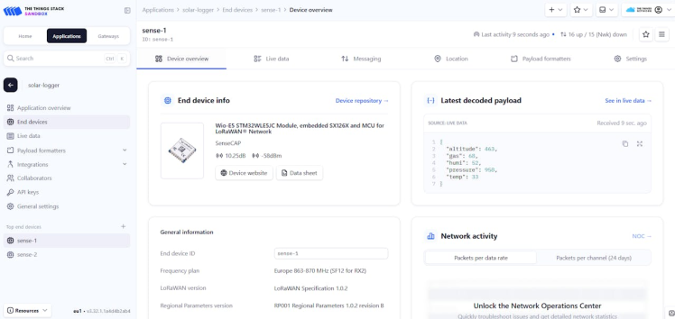
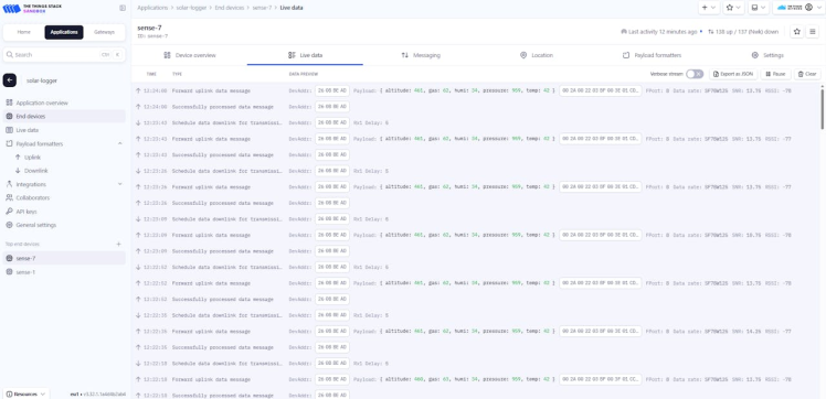
here is the final TTN setup with live data.
I have used this payload format.
function Decoder(bytes, port) {
var decoded = {};
if (port === 8) {
decoded.temp = bytes[0] <<8 | bytes[1];
decoded.humi = bytes[2] <<8 | bytes[3];
decoded.pressure = bytes[4] <<8 | bytes[5];
decoded.gas = bytes[6] <<8 | bytes[7];
decoded.altitude = bytes[8] <<8 | bytes[9];
}
return decoded;
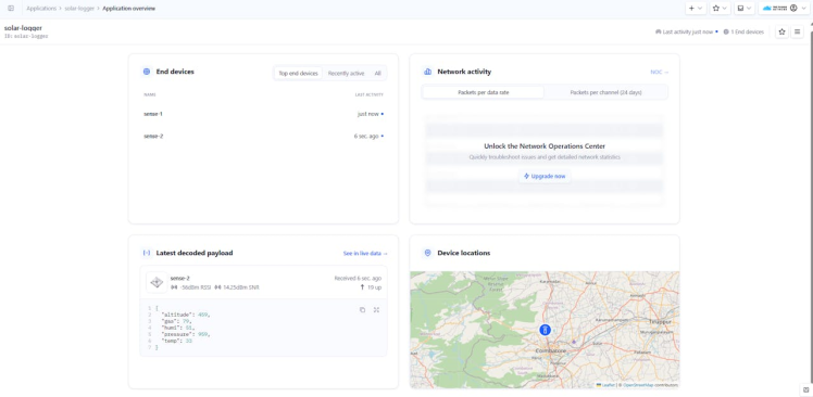
}Finally, you can see all the complete 5 data in the TTN dashboard.
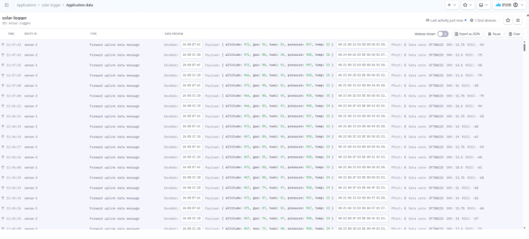
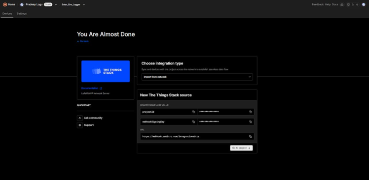
Step 8: Qubitro Data Visualization:
Qubitro is a versatile IoT platform that allows you to connect, manage, and analyze data from various IoT devices. When integrated with The Things Network (TTN), it provides a powerful solution for visualizing LoRaWAN data.
Steps to Visualize TTN Data with Qubitro
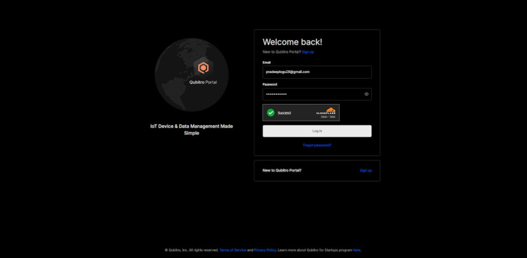
1.Set Up Accounts:
Qubitro: Sign up for a Qubitro account if you don’t have one. Qubitro offers free and paid plans depending on your needs.
The Things Network: Ensure you have a TTN account and your devices are registered and sending data to the TTN network.
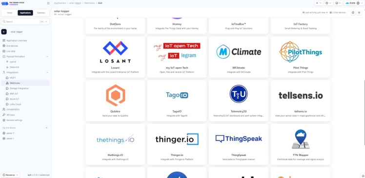
2. Integrate TTN with Qubitro:
Data Forwarding: Configure TTN to forward data to Qubitro. This typically involves setting up a webhook integration in the TTN console, where you provide the Qubitro API key.
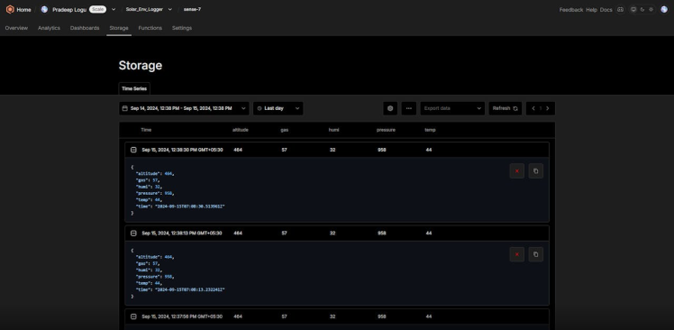
Device Management: In Qubitro, add your TTN devices. You can use Qubitro’s device management features to organize and monitor your devices.
Data Processing: Qubitro allows you to process and transform incoming data on the fly, making it easier to work with different data formats.
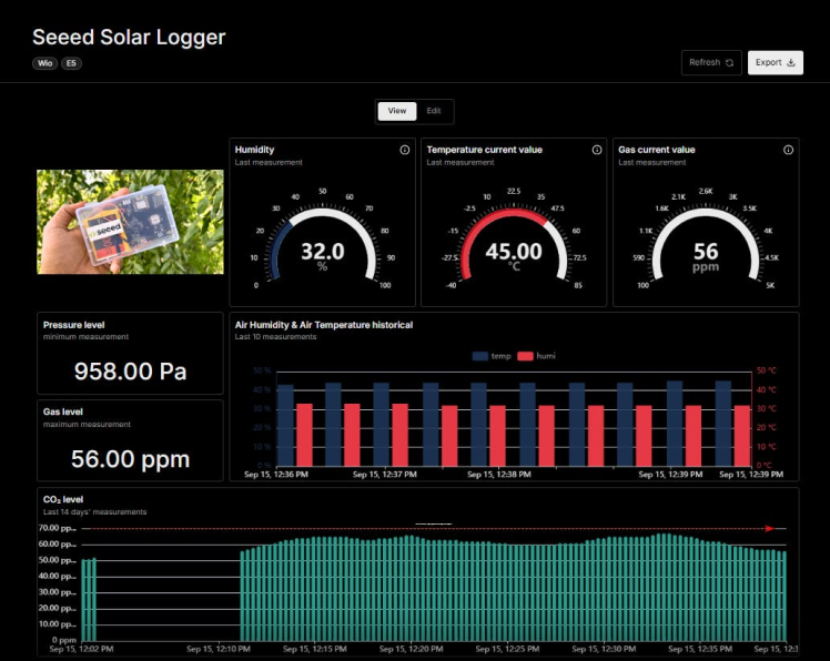
3. Visualization:
Dashboards: Use Qubitro built-in dashboard features to create visualizations. You can create graphs, charts, and tables to display your IoT data.
Grafana Integration: For more advanced visualizations, you can integrate Qubitro with Grafana. Qubitro supports the Infinity plugin in Grafana, allowing you to visualize data from JSON, CSV, XML, and other formats.
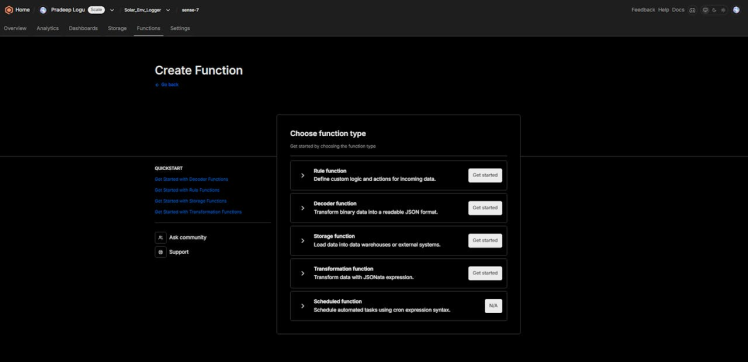
4. Custom Alerts and Notifications:
Qubitro Functions: Set up custom alerts and notifications based on your data. Qubitro allows you to define rules and triggers to notify you of specific events or conditions.
5. Benefits of Using Qubitro with TTN
- Scalability: Qubitro can handle a large number of devices and data points, making it suitable for both small and large-scale IoT deployments.
- Flexibility: With support for multiple data sources and integration options, Qubitro provides a flexible platform for various IoT applications.
- Ease of Use: Qubitro’s user-friendly interface and extensive documentation make it easy to set up and manage your IoT projects.
By leveraging Qubitro and TTN, you can create a robust IoT solution that not only collects and processes data but also provides meaningful insights through powerful visualizations.
Conclusion

Creating a solar-powered environmental logger with LoRa has been a fulfilling and innovative project. By harnessing solar energy and leveraging long-range communication, we've developed a robust solution for remote environmental monitoring. This project not only showcases the potential of renewable energy but also emphasizes the importance of continuous data collection for environmental insights.
Key accomplishments of this project include:
- Sustainable Power Source: The use of solar panels ensures that the logger operates independently, reducing the need for frequent maintenance and battery replacements.
- Comprehensive Environmental Monitoring: Equipped with the BME680 sensor, the logger provides accurate measurements of temperature, humidity, pressure, and gas levels, offering a holistic view of environmental conditions.
- Long-Range Communication: The integration of the LoRa module enables data transmission over long distances, making it ideal for remote and hard-to-reach locations.
- Compact and Efficient Design: The combination of components on a single PCB ensures a reliable and compact solution, suitable for various deployment scenarios.
This project demonstrates the synergy between renewable energy and advanced communication technologies, paving the way for innovative solutions in environmental monitoring. Whether for agricultural applications, climate research, or smart city initiatives, this solar-powered environmental logger with LoRa is a step towards a more sustainable and connected future.
Thank you for following along with this project. We hope it inspires you to explore further innovations in renewable energy and environmental monitoring.
Credits
Related products


Leave your feedback...