

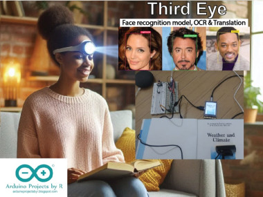
Third Eye: Face Recognition Model, Ocr (read) & Translation

Made by RucksikaaR / Artificial intelligence / Displays / Photos & Video / Security / Voice
About the project
Third eye is an assistive device for the visually impaired that integrates face recognition model, OCR & Translation system (7 languages)
Project info
Difficulty: Difficult
Platforms: DFRobot, Google, Seeed Studio, SparkFun, STMicroelectronics, Edge Impulse, Jupyter
Estimated time: 1 day
License: GNU General Public License, version 3 or later (GPL3+)
Items used in this project
Hardware components


View all
Software apps and online services
Story
Visually impaired people face several challenges in life, and technology can ease this for them. Being disabled should not stop them from enjoying their life like the others and they should not miss out on the smallest of happy moments of their life.
Social interaction is one of the hurdles faced in the daily lives of visually impaired individuals when they go out and they might not be able to recognize a person unless he/ she introduces themselves. This might lead to social isolation or a feel of discomfort within the individual. Disability might be a weakness but it should not burden the person and make them feel uneasy as if they are being discriminated.
Recognizing a person is important for visually impaired individuals, especially when they have to identify someone visiting their home. Distinguishing between familiar visitors and intruders/ unwelcome guests can improve the individuals' safety and sense of security.
Another challenge faced is reading, like reading travel guides and street signs, or understanding product labels in supermarkets and department stores, or reading a book indoors or studying. Although there are assistive technologies available, not all of them are affordable and user friendly, while some might not helpful enough.
Objective
My project will be focusing on addressing some of the key challenges faced by visually impaired individuals:
- Social interaction
- Visually impaired individual's sense of security when staying indoors
- Access to information
- Education
- Technological barriers
I call my prototype as the Third Eye and I have developed this device to enhance the daily lives of the individuals. This prototype enables the users to recognize both familiar visitors and unwelcome guests through facial recognition system, given that their data has already been fed to the model.
Secondly, this user friendly prototype incorporates an OCR (Optical Character Recognition) solution to assist the users with reading printed text. The device currently supports seven languages at the moment, and they are:
- English
- Simplified Chinese
- Spanish
- French
- German
- Tamil
- Korean
Note: The languages are listed in order of popularity
The user can select their preferred language and the printed text will be read out aloud by the Third eye. The visually impaired individual can listen to it through either a Bluetooth speaker or earbuds, whichever is convenient.
And last but not least, this prototype also provides a translation service which can translate the text to the user's desired language (out of the seven available languages, for now).
The OCR and translation features are beneficial for individuals who wish to develop a hobby like reading, visually impaired students who need to access text based educational materials, or even for everyday tasks like reading grocery labels at home.
Arduino IDE
Arduino IDE is an open-source software to write code and upload it to your microcontroller. It uses a variant of C++ programming language, where the code is written in C++ and is then compiled into machine language.
There is a cloud editor, where you can upload and access your projects anytime from your browser, and your projects will be saved in the Arduino cloud. There is the Arduino IDE software as well and this requires no internet connection (except during the first run and the installation of libraries and boards).
You can choose whichever is convenient for you but I suggest you to use Arduino IDE 2.0 or higher. However, you can use Arduino IDE 1.8.19 if you have internet connectivity issues.
I have used this software to program both Seeed Studio XIAO ESP32S3 Sense and the STM32F411 "BlackPill" Development Board.
Seeed Studio XIAO ESP32S3 Sense


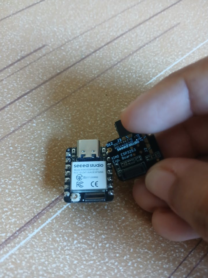

Seeed Studio XIAO ESP32S3 Sense
The Seeed Studio XIAO ESP32S3 Sense integrates the Seeed Studio XIAO ESP32S3 development board with the OV2640 camera sensor, digital microphone and SD card support.
Third Eye, my prototype, uses the Seeed Studio XIAO ESP32S3 Sense to recognize faces and distinguish familiar visitors and unwelcomed guests from other guests. If the person is recognized, the name of the person is notified to the user in the form of Morse code so that the user will be able to know their visitor by placing the camera over the peep hole of the door. If the person is unrecognized, the model will not produce an output.
You can view the product's page to learn more about this amazing product's specifications and informative tutorials to help you get started.
The next few sections of this documentation will show you how I developed a facial recognition model and how it was deployed to this Mini ESP-CAM development board.
Edge Impulse
Edge Impulse is a platform which can help users to build, refine and deploy machine learning models to their devices. The free plan has limited features but they are sufficient when you want to build a simple machine learning model.
I used this platform to build a face recognition model to identify familiar visitors and unwelcome guests.
1. Target Device [Edge Impulse]
When you first create an Edge Impulse project, you will be directed to its dashboard where you can choose from an existing dataset or collect new data to train your image classification model, or even upload your own model, or go through some tutorials to help you kickstart your project.

The first step is to choose your target device and this helps you optimize your impulse for your specific target device. Optimizing your impulse will ensure that the model runs efficiently on your hardware.


Choose Espressif ESP-EYE(ESP32 240MHz) as the target device as it is more similar to the Seeed Studio XIAO ESP32S3.
And, under Project Info of your project's dashboard, make sure that Bounding boxes (object detection) is chosen as the labeling method.
2. Data Acquisition [Edge Impulse]
Data is essential to build a machine learning model and in most cases, the accuracy of a machine learning model is proportional to the number of training data samples.
I used a celebrity face image dataset from Kaggle (author: Vishesh Thakur) to train my image classification model. This dataset, licensed under CC0: Public Domain, contains images of 17 different celebrities. Each directory has 100 images of the respective celebrity.
I chose the images of three different celebrities: Angelina Jolie, Robert Downey Jr, and Will Smith, to train my facial recognition model. While the visually impaired individual might not encounter Angelina Jolie as a familiar visitor or Robert Downey Jr. as an unexpected guest, I have trained my model with their images to demonstrate how this project works, and the accuracy of the model in recognizing and distinguishing between familiar and unfamiliar faces in real-world scenarios.
Although the accuracy is proportional to the number of training data samples, the quality of the samples is also crucial. It is always good to check your training images before you proceed to train your model.
The next step is to choose the upload mode, select your files, choose the category, assign the respective labels, and upload your data. You can select Automatically split between training and testing, and 80% of the uploaded dataset is assigned as the training dataset while the remaining 20% is assigned as the testing dataset.


Labeling the dataset
After uploading your dataset, it is time for you to add labels to the dataset so that you can proceed with the other steps. To do this, go to the Labeling queue on the top beside Dataset and Data sources tabs and you can choose from the available Label suggestions options to help you label your dataset. You are also free to use your own pretrained object detection model. I have used Track object between frames to help me label the faces of the celebrities in my dataset.

Label suggestions

Labeling using YOLOv5

Labeling using 'Track objects between frames'

How the labeling should look like in the end
3. Create impulse [Edge Impulse]
It is time for you to create your impulse which takes in your data, extracts the features, and classifies the test data using a learning block. A complete impulse has 3 main building blocks which are:
- Input block
- Processing block
- Learning block
A project can have multiple impulses (3 impulses if you are using the Free Community Plan) and this is called Experiments, where each impulse consists of the same combination of blocks or a different one. This can help you to compare the performance of each combination and choose the one that works best, while they all use the same training and test dataset.
This is my impulse design for this machine learning model:

Impulse - Initial

Impulse - Final
Input block
The input block designates the type of data used to train your model, which, in this case, is images. The block is automatically chosen after you upload your data.
All you have to do is modify the image dimensions and the resize mode, whereas the axes is already chosen and is Images in this case. It is better to resize the images to square dimensions as most of the Edge Impulse pre-trained models work best with square images.
As for the resize mode, there are three options available:
- Squash - Squashes the image so it fits into the set size
- Fit to the shortest axis - Crops the image so that the shortest axis will fit
- Fit to the longest axis - Fits the longest axis and adds padding to maintain the aspect ratio.
I have chosen Fit shortest axis for the resize mode.
Processing block
The processor block is basically a feature extractor, and consists of operations that extract the features for the model to learn on. These operations depend on the type of data used in the project.
In the image below, you can see various processing blocks. You can choose the one best suited to your model and if you are not familiar with this, you can choose the recommended processing block indicated by the yellow star. For those who think the existing processing blocks do not match your needs very well, you are free to create a custom processing block with your own DSP (Digital Signal Processing) code.

I chose the Image processing block as it was most suited to my model.
Note: For those who are interested in creating a custom processing block, please check out the embedded hyperlink.
Learning block
The learning block is the final component of an impulse, and it is a neural network that is trained to learn your data. Learning blocks vary depending on the aim of your model and the type of data in your training dataset.
The image below shows you all the available algorithms (more options available for Enterprise users), and you are free to create your own custom learning block. Unfortunately, only users who are subscribed to the Enterprise plan are allowed to bring their own model.
 learning block")
Choose the Object Detection (Images) learning block
I chose the ObjectDetection Learning(Images) learning block as it was most suited to my model. Pre-trained model comes in handy when you are using a relatively small dataset and they can accelerate model development while improving AI application performance.
Note: For those who are interested in creating a custom learning block, please check out the embedded hyperlink.
4. Pre-processing [Edge Impulse]
In addition to resizing your images, you can choose to change their color depth. Choosing grayscale will give 9,216 features (96x96x1) whereas RGB will give 27,648 features (96x96x3). You can choose grayscale to help reduce the amount of final memory needed for interference. I chose RGB as I got better accuracy (train and test) with this color depth.

Raw Data

Parameters - Generate features

On-device performance - Generate features
Once you are done choosing the parameters, click on Save parameters and you will be redirected to the Generate features tab. This will show you the details of your training set and you can click on Generate features when you are ready. Doing this will generate the features which will be used in training, and you will also see the Feature explorer.

Generate features - Training set

Feature explorer - Generate features
5. Training [Edge Impulse]
The next step is Training and this is where you will select your Neural network settings and the appropriate model for your neural network architecture.
Training settings
I tried several combinations of epochs and learning rate and the one that gave me best results were 60 epochs (60 training cycles) and a learning rate of 0.005.

Training settings
Choosing the optimal number of epochs
The number of training cycles (epochs) is an important hyperparameter for the training process, and an epoch means one complete pass through the entire dataset by the learning algorithm. The number of epochs chosen is important as it allows the machine learning model to learn from the dataset and adjust its parameters.
Training with too few epochs can lead to an underfitted model, where the model hasn't had sufficient time to learn patterns from the training data, resulting in poor predictive accuracy.
On the other hand, training with too many epochs risks overfitting, where the model not only learns the underlying patterns but also memorizes noise and specific details in the training data. This overfitting can cause the model to perform poorly on new, unseen data, as it fails to generalize effectively.
Choosing the optimal learning rate
Like the number of epochs, choosing the optimal learning rate is crucial for the effective training of a neural network. This tuning parameter determines how quickly or slowly a model learns from the data, influencing both the speed of convergence and the accuracy of the final model.
A high learning rate allows the model to make rapid progress by taking larger steps toward minimizing the loss function. However, this can be a double-edged sword. If the learning rate is too high, the model might overshoot the optimal point repeatedly, leading to unstable training and poor results.
On the other hand, a low learning rate ensures more careful and precise updates to the model’s parameters, which can help to avoid overshooting. But this comes at the cost of slow convergence, and in some cases, the model might become trapped in local minima, unable to reach the global minimum loss.
To find the right balance, it's often necessary to experiment with different learning rates, tuning this parameter to achieve the fastest and most reliable convergence without compromising accuracy.
Data augmentation
Data augmentation is enabled because it improves the accuracy of the model, by adding in modified copies of existing data or by synthesizing new data. This can help reduce the risk of overfitting as it makes the dataset more diverse while also expanding its size. This is particularly helpful when you have smaller datasets.
Advanced training settings
This is where you will be specifying the settings for validation, which is crucial to avoid overfitting and underfitting your model. I have chosen the default Validation set size as 20% and the Batch size as 32.

Advanced training settings
Neural network architecture
The neurons of a neural network are organized into layers which are:
- Input layer: Receives raw input data
- Hidden layers: Performs computations using weighted outputs
- Output layer: Produces the final output
In my case, my neural network architecture has an input layer with 27, 648 features (generated during pre-processing), FOMO MobileNetV2 0.1 for the hidden layer and an output layer with 3 classes (Angelina Jolie, Robert Downey Jr, and Will Smith).
You have the flexibility to choose a different model, customize it according to your needs, or even bring your own model.
After experimenting with the FOMO MobileNetV2 0.35, I opted for FOMO MobileNetV2 0.1 that has a role width multiplier (α) of 0.1. This model provided better accuracy results so this is the optimal choice in my project.

Neural network architecture

Choose a different model - Neural Network
Results
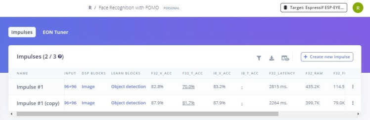
Impulse #1 is where I used the FOMO MobileNetV2 0.35 and the input's resize mode was Squash instead of Fit to the shorter axis. Impulse #1 (copy) was what I have been demonstrating to you throughout this documentation. As you can see, this impulse shows better results.
I gained a validation accuracy of 87.9% and I am happy with my results as this accuracy is not only ideal but also realistic, and fits the industry standards (stated as 70-90%).
Precision measures the accuracy of positive predictions, or in other words, it shows how often a machine learning model is correct when predicting the target class. Recall measures the completeness of positive predictions, and shows whether a machine learning model can find all objects of the target class. The F1 score balances precision and recall on the positive class.

F1 score

Confusion matrix - Validation set

Metrics - Validation set

On-device performance
6. Testing [Edge Impulse]
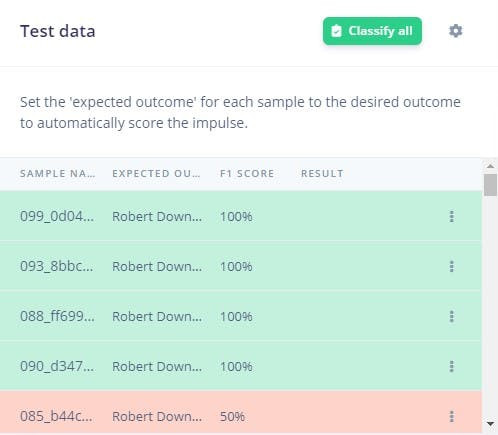
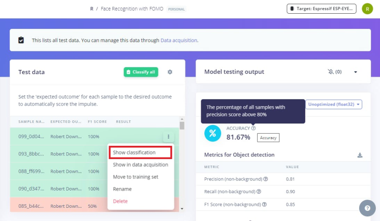
It is time to test your model, so go to Model Testing and select Classify all. You will see your results in a few seconds or a minute, and your model will classify all of your test samples and provide you with an overall accuracy of your model's performance.
My test accuracy is 81.67% and the results look promising as well.

Test accuracy

Metrics for Object detection

Feature explorer
Confidence threshold
My neural network has a minimum confidence of 50% and this is the default value chosen by Edge Impulse. You can tweak it based on your needs by clicking on the settings icon on the right of Classify all button.
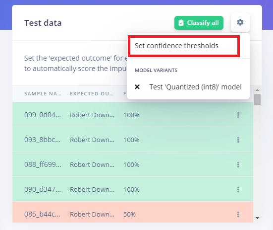

Set confidence threshold
Increasing the confidence threshold to 90% gave me 70.31% test accuracy.

Test accuracy - 90% confidence

Metrics - 90% confidence

Feature explorer - 90% confidence
Evaluating individual samples
You can choose to evaluate individual samples from your test dataset or you can even view the detailed classification of new data. This can be done in Live classification where you can view the expected outcome, and the predicted outcome with its accuracy. You can also view the confidence rates of each labels and this can give you an understanding about how important the confidence threshold is and why your sample was misclassified (if it was misclassified).

Correct classification

Misclassified
 not being greater than the threshold")
Misclassified because of confidence (F1 Score) not being greater than the threshold

Overlaid classification result

Unlabeled data - No predictions
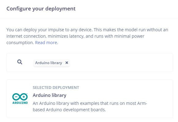
7. Deployment [Edge Impulse]
The trained model will be deployed as a.zip Arduino library. Deploying your model to the device will help it run without an internet connection and with minimal power consumption.
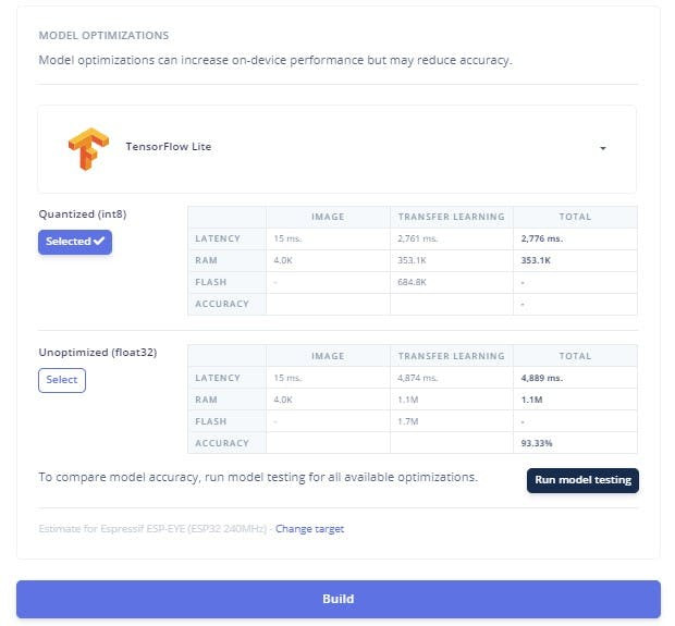
You have a variety of deployment options to choose from, and you have to choose Arduino library as we will be deploying the model to the XIAO Seeed ESP32S3 Sense using the Arduino IDE. Make sure you choose the Quantized (int8) version and TFLite compiler option. Once you are done, select Build option and your model will be downloaded as a.zip folder.
8. Deployment [SenseCraft-Web-Toolkit]
Before we deploy the Face recognition model to the XIAO ESP32S3 Sense, let us try the model with the SenseCraft-Web-Toolkit, as we cannot see what the camera focuses on when we deploy the model to the microcontroller.
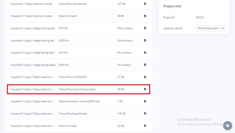
To do this, first go to your project dashboard on Edge Impulse and under Download block output, download the Tensor flow lite (int8 quantized) version of your model.
Next, click on the embedded hyperlink (SenseCraft-Web-Toolkit) to access the web application. Once you're on the site, connect the XIAO ESP32S3 to your computer, and then select Connect on the preview page. You'll be prompted to choose the serial port make sure to select the correct one for your device to establish the connection successfully.
After successfully connecting your microcontroller, the next step is to upload your AI model. To do this, select Upload Custom AI Model, which will open a dialogue box. Upload your model file, complete the required fields, and then click Send Model to finalize the upload.

SenseCraft-Web-Toolkit Preview Page

Select the correct Serial Port to establish the connection

Time to upload your model

Fill in the fields correctly and upload your model file
Once your model has been successfully uploaded, the real-time camera image will appear in the Preview Sector. The centroid of the detected objects (in our case, faces) will be marked with the label and confidence value. The confidence of your model can be adjusted using the Confidence slider, and the IoU slider can be adjusted to assess the accuracy of predicted bounding boxes compared to the ground truth bounding boxes.

Angelina Jolie

Robert Downey Jr

Will Smith
")
Kate Winslet (unlabeled)
Deployment [Arduino IDE]
Now that you have had a preview of how your model works, it is now time for you to deploy the model on the XIAO ESP32S3 Sense.
1. Installing the XIAO ESP32S3 on Arduino IDE
Before you can deploy your model to the development board, you should first install your board on the software. To do this, open Arduino IDE and navigate to File menu. You should see Preferences in the menu. Select it and fill in the following URL:
https://raw.githubusercontent.com/espressif/arduino-esp32/gh-pages/package_esp32_dev_index.json
Step 01: Navigate to Preferences

Step 02: Open the Additional boards manager by clicking on the icon next to the entry box

Step 03: Paste the URL
The next step is to install the board's package. You can do this by navigating to the Tools menu and going to Boards where you can find the Board Manager... Open the Board Manager and enter esp32 in the search bar. You can find the esp32 package by Espressif Systems.

Step 04: Open Boards Manager

Step 05: Install the esp32 package

Step 06: Select the XIAO ESP32S3 as your board

Step 07: Choose port from 'Select other board and port...' if port is not automatically detected
Note: Make sure you install the last stable version released before the Alpha versions (3.x) as they do not work correctly with XIAO and Edge Impulse.
2. Deploying the model [Arduino IDE]
Let us add our model now. To do this open Arduino IDE, and under Sketch menu, go to Include Library and add.zip library. Once you do this, a dialogue box opens up asking you to choose the.zip folder and you just have to choose the.zip folder that was downloaded when you built the library during the deployment process.
After the library is successfully installed, go to Examples under File menu and you can find the library that you just added. Hover your cursor over it and navigate to esp32 where you will find the esp32_camera.ino sketch file.
As the target device was specified as ESP-EYE, you might want to modify something in the sketch file as the model is going to be deployed on the XIAO ESP32S3.
#define PWDN_GPIO_NUM     -1
#define RESET_GPIO_NUM    -1
#define XCLK_GPIO_NUM     10
#define SIOD_GPIO_NUM     40
#define SIOC_GPIO_NUM     39
#define Y9_GPIO_NUM       48
#define Y8_GPIO_NUM       11
#define Y7_GPIO_NUM       12
#define Y6_GPIO_NUM       14
#define Y5_GPIO_NUM       16
#define Y4_GPIO_NUM       18
#define Y3_GPIO_NUM       17
#define Y2_GPIO_NUM       15
#define VSYNC_GPIO_NUM    38
#define HREF_GPIO_NUM     47
#define PCLK_GPIO_NUM     13
This is how your modified sketch should look like in the end

If the compilation fails, you can try removing the ESP-NN folder by navigating to the directory: Arduino/libraries/<your-ei-project-name>/src/edge-impulse-sdk/porting/espressif/ESP-NN/. Delete the entire ESP-NN folder as this prevents the build process from attempting to link to unsupported ESP-NN files, which causes the compilation errors.
Afterwards, you will have to modify the ei_classifier_config.h file by navigating to its directory: Arduino/libraries/<your-ei-project-name>/src/edge-impulse-sdk/classifier/. Go to line 68, and change this:
#define EI_CLASSIFIER_TFLITE_ENABLE_ESP_NN 0
to
#define EI_CLASSIFIER_TFLITE_ENABLE_ESP_NN 1
Your Arduino sketch should compile fine now.
3. Communication with STM32F411 "BlackPill" Development Board [Arduino IDE]

Pin allocation diagram - XIAO ESP32S3 Sense
The XIAO ESP32S3 Sense will send its output to the STM32F411 "BlackPill" Development Board via Serial communication. As you can see from the pin allocation diagram, we can see a TX and RX pin. We will be connecting these pins to one of the RX and TX pin pairs of the STM32F411.
Declare the following variables before void setup( ):
const char *label; // to store bb.label
char incomingByte; // variable to receive incoming byte data from the STM32F411
The output of the face recognition model will be sent to the STM32F411 development board when you press the push-button connected to PA8 pin on the BlackPill board. Pressing the button will send a byte via serial communication and once the specific byte is received, the face recognition model's output will be sent to the BlackPill board.
The following code as to be edited to add in the changes:
#if EI_CLASSIFIER_OBJECT_DETECTION == 1
ei_printf("Object detection bounding boxes:rn");
for (uint32_t i = 0; i < result.bounding_boxes_count; i++) {
ei_impulse_result_bounding_box_t bb = result.bounding_boxes[i];
if (bb.value == 0) {
continue;
}
label = bb.label; // if bb.value is not zero, then assign label variable to bb.label
ei_printf(" %s (%f) [ x: %u, y: %u, width: %u, height: %u ]rn",
bb.label,
bb.value,
bb.x,
bb.y,
bb.width,
bb.height);
}
if(Serial1.available() > 0){ // this is when the Serial communication will be established with the STM32F411
incomingByte = Serial1.read(); // assign incomingByte variable to receive the byte sent by the STM32F411
if (incomingByte=='1'){
Serial1.print(label); //if the specific byte is received, send the output of the model to the STM32F411
}
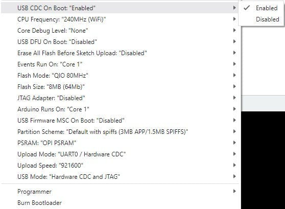
}Make sure the following options are set accordingly:
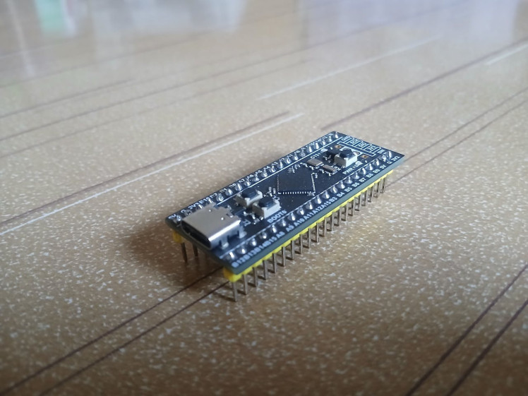
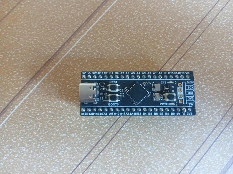
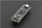
The STM32F411 "BlackPill" Development Board is a simple development board featuring the STM32F411CEU6 chip (ARM Cortex-M4 core) which incorporates high-speed embedded memories (up to 512 Kbytes of flash memory, 128 Kbytes of SRAM) and has multiple UART, I2C, SPI, I2S, and timer peripherals.
This chip is compatible with Arduino, MicroPython, and CircuitPython, offering flexibility in programming environments. For this project, I chose to use the Arduino IDE to program the development board.
Pin allocation diagram to interface the development board with Micropython and Arduino

In this project, the board will primarily handle serial communication with the XIAO ESP32S3 and UNIHIKER, functioning as both a client and a server. This dual role is for different purposes:
- XIAO ESP32S3 - Morse code transmitter
- UNIHIKER - Input language choice
1. Installing the STM32F411 on Arduino IDE
You should first install your board's package on the software. To do this, open Arduino IDE and navigate to File menu. You should see Preferences in the menu. Select it and fill in the following URL:
https://github.com/stm32duino/BoardManagerFiles/raw/main/package_stmicroelectronics_index.jsonFollow the steps as shown in the Installing the XIAO ESP32S3 on Arduino IDE section. Once you are done, open the Board Manager and enter stm32 in the search bar. You can find the STM32 MCU based boards package by STMicroelectronics.

Install the STM32 package to get started
2. STM32CubeProg
The STM32CubeProgrammer, also known as STM32CubeProg, is an all-in-one multi-OS software tool for programming STM32 and external memories connected to STM32.
You will need this software tool before you can start programming your development board with Arduino IDE.
To download the STM32CubeProg, follow the embedded hyperlink and you will be redirected to the official webpage where you can scroll down and find Get Software. You can download the appropriate software for your OS and to download, you can either create an account or download it as a guest.
Provide your email address and the download link will be sent to your email. Download the.ZIP package on the device you requested the download link and once it is done, unzip the folder, and run the installation file.
Download the appropriate software

Download the appropriate software
3. Enable DFU bootloader
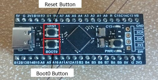
Before you can upload the program to your development board, you will have to set it to DFU bootloader mode. To do this, you will have to use the onboard BOOT0 and NRST buttons.
Start by connecting your STM32F411 development board to your laptop or PC using a USB cable. This connection will enable communication between the board and your computer.
Next, press and hold the BOOT0 button. While keeping the BOOT0 button pressed, press and release NRST (reset) button to power cycle the processor. Release the BOOT0 button after a second. You should now see the DFU port accessible in the Ports section under Tools menu. If that does not work, try grounding the A10 pin. Doing this should work and your USB device will be recognized.
You are now all set to begin programing with the STM32F411 "BlackPill" Development Board.
Note: Enter DFU mode to upload your sketch to the STM32F411 development board.

Make sure the correct options are selection before you upload your code
4. Serial Communication & Buzzer [XIAO ESP32S3 Sense]
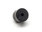
We saw that the XIAO ESP32S3 Sense was programmed to recognize faces in this project. To effectively notify the user of the model's results, the output needs to be communicated in a way that captures their attention. This can be achieved by either haptic feedback or Morse code. As I did not have any actuators capable of generating the haptic feedback, I opted for Morse code as the mode of output.
While the XIAO ESP32S3 can also be connected to the buzzer, I chose to handle this task with the STM32F411 "BlackPill" Development Board instead. This approach can help to offload some of the processing demands from the Mini ESP-CAM development board, allowing it to operate more efficiently and focus on the face recognition.
The XIAO ESP32S3 will be communicating with the STM32F411 "BlackPill" Development Board via Serial communication. As already mentioned, pressing the push-button connected to PA8 pin on the BlackPill development board should send a byte data to the XIAO ESP32S3 which then will transmit the face recognition model's output on receiving the byte data.
Once the model's output is received, it will be passed on to the Morse Code encoder function resulting in the output of Morse code by which the user will be able to decipher the name of the familiar visitor/ unwelcome guest.
Coding
#include <SoftwareSerial.h>
SoftwareSerial XSerial(B6,B7); //Software Serial XSerial(RX,TX) - Communication with XIAO ESP32S3 Sense

void setup() {
// put your setup code here, to run once:
    XSerial.begin(9600);
    pinMode(PA8, INPUT);
...
}
A dot in the Morse code is like a short sound and it should last for 100 milliseconds.
void dot(){
    tone(buzzer,200); // Emits sound at 200Hz
    delay(100);
    noTone(buzzer); // Stops emitting the sound
    delay(100);
}
A dash in the Morse code is a long sound which should last for 300 milliseconds.
void dash(){
    tone(buzzer,200); // Emits sound at 200Hz
    delay(300);
    noTone(buzzer); // Stops emitting the sound
    delay(100);
}
We should now create a function which can take in the output from the model and generate the Morse code.
Morse Code for Standard English letters

Morse Code for Standard English letters
If the push-button (PA8) is pressed, it should send a byte data to the XIAO ESP32S3 and then receive the model's output. This can be done by:
if(digitalRead(PA8)==LOW){
    XSerial.println("1");
    n = XSerial.available();
}
if (n != 0)
{
    char ch = XSerial.read();
    Morse(ch);
}
delay(300);
5. Serial Communication, Bluetooth & Buttons [UNIHIKER]
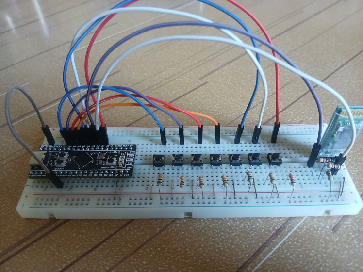
The STM32F411 "BlackPill" Development Board will serve as the interface for selecting language options on the UNIHIKER. This will be achieved using push-buttons, with each button corresponding to a different language. By pressing a button, users can easily input their language choice, making the system intuitive and user-friendly.
The buttons are arranged nearby each other which can make it easy for the visually impaired individual to feel the buttons and press the button of their choice. This can be done as long as they remember the order of the buttons and their corresponding language codes, like first button for English, second one for Simplified Chinese, etc.
Since this prototype supports seven different languages, we'll require seven push-buttons, one for each language. Due to the fact that the INPUT_PULLUP functionality wasn't effective on the BlackPill development board, it's necessary to use a 10k ohm resistor in conjunction with each button. This ensures proper pull-up resistance, allowing for reliable detection of button presses.
Similar to the XIAO ESP32S3, the UNIHIKER is also capable of interfacing with the STM32F411 "BlackPill" development board via serial communication. However, since the USB port on the UNIHIKER will be occupied for another purpose (refer to the UNIHIKER section), and I was lacking a UART to SPI Bridge, I opted to connect these two devices via Bluetooth. This wireless solution ensures seamless communication between the boards without interfering with the existing USB connection.
Bluetooth configuration
The STM32F411 "BlackPill" Development Board lacks built-in Bluetooth connectivity, so to add this capability, I used an HC-06 Bluetooth module. Alternatively, an HC-05 module can also be used. This addition will allow the STM32F411 development board to wirelessly communicate with the UNIHIKER.
As shown in the pin allocation diagram, the STM32F411 offers multiple TX and RX pin pairs. Just as you've connected one pair (B6 and B7) to the XIAO ESP32S3, you can utilize another pair for the Bluetooth module.
Connect to the Bluetooth module as shown in the schematic in the Schematic section.
Please refer to my tutorial to configure the Bluetooth module and test its connectivity. The tutorial focuses on interfacing the HC-06 with Arduino microcontroller but it can be used for the BlackPill development board as well because the process is the same whether it is an Arduino microcontroller or the STM32F411. To test the Bluetooth connectivity, download a Bluetooth terminal app, something like the Serial Bluetooth Terminal.
Once your Bluetooth module is successfully configured, the next step is to integrate the push-buttons and program the microcontroller. Each button should be mapped to a specific language, and pressing a button will transmit the corresponding language selection over the Bluetooth connection.
Since the HC-06 module operates as a slave device, you will need to handle the pairing and connection process using the UNIHIKER. You will see how this is done in the 2. Connecting to Bluetooth devices [PuTTY] section.
#include <SoftwareSerial.h>
SoftwareSerial BTSerial (PA2,PA3); //SoftwareSerial BTSerial(RX,TX) - Communication with UNIHIKER

void setup() {
// put your setup code here, to run once:
    BTSerial.begin(9600);
...
}
Each button should be programmed to send the language code of the corresponding languages, over the Bluetooth connection, once they are pressed.
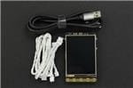
UNIHIKER - IoT Python Single Board Computer with Touchscreen
1 / 5
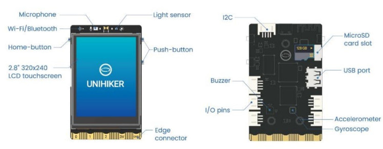
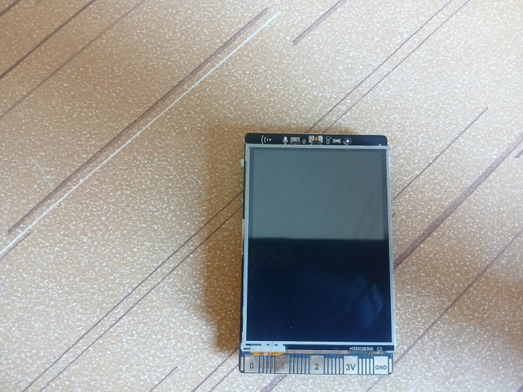

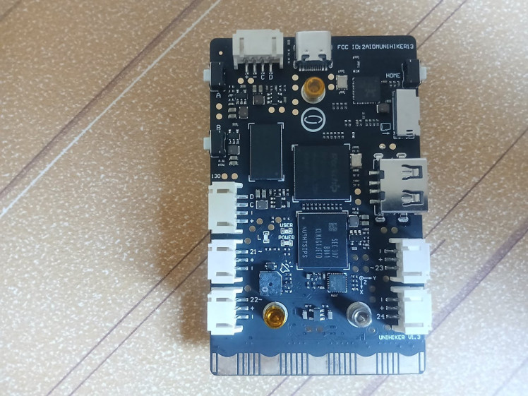
UNIHIKER is a single-board computer that features a 2.8-inch touchscreen, Wi-Fi and Bluetooth. As shown above, it is equipped with a light sensor, microphone, accelerometer, and gyroscope. It has a built-in co-processor, it is able to communicate with various analog, digital, I2C, UART, SPI sensors and actuators.
It has built-in IoT service and built-in Jupyter Notebook, which is a browser-based programming environment and makes it easier to program the UNIHIKER using even a smartphone or tablet.
The OCR solution and translation service are implemented on the UNIHIKER, and the device's two buttons are used to Read and Translate. The webcam is connected to the UNIHIKER's USB port so that it can capture the image from which the text will be read or translated using the OCR solution.
PuTTY
PuTTY is a popular SSH (Secure Shell), Telnet (Text-based network protocol), and SFTP (Secure File Transfer Protocol) client that is open-source and makes it convenient to connect to a remote server and transfer files over the network.
I used PuTTY to connect the UNHIKER to the Bluetooth devices and install the necessary Python packages. The UNIHIKER has SSH service enabled by default, so we can use SSH tools like PuTTY or MobaXterm to connect it from another computer.
If you do not have this software, you can follow the embedded hyperlink where you can download the suitable PuTTY package. After the installation, you can open the PuTTY software and enter the IP address of UNIHIKER to get started.
Once you connect the UNIHIKER to your computer via USB, the IP address is fixed at 10.1.2.3. You can find the IP address in the Home menu of the UNIHIKER.
Use the following login credentials to connect to the UNIHIKER using SSH:
- SSH Username: root
- password: dfrobot
The password will be invisible when you type them so do not panic when you do not see the characters being typed in. Enter the credentials and press Enter key to continue.

Download PuTTY

Download the suitable package file

Enter your IP address
1. Installing Required Libraries [PuTTY]
The UNIHIKER is responsible for reading and translating text captured by the webcam. It will process the image, extract the text, and perform the following actions:
- Read out loud - If Button A is pressed
- Translate - If Button B is pressed
To accomplish this, a few essential Python packages will be required. I used PuTTY to access the terminal and install these packages, ensuring the environment is properly configured for the task at hand.
The first step is to connect the UNIHIKER to your computer using the USB cable, and open your browser where you can enter the website address 10.1.2.3 and access the local web page menu on the UNIHIKER.
Go to Network Settings and connect to your Wi-Fi to obtain the IP address.
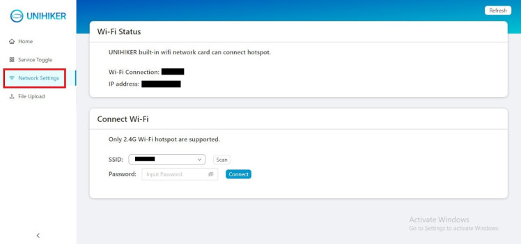
Now, open the PuTTY software and connect to the UNIHIKER with this IP address, SSH username (root) and password (dfrobot).
First, you have to view the Python libraries installed in the UNIHIKER as you do not want to end up with incompatible versions of different libraries (like Torch and Torchvision) or similar libraries (opencv-python and opencv-contrib-python) which can cause an error while you run the Python notebook.
To check compatible versions of Torch and Torchvision, please refer here.
Run the following command to view the installed packages:
pip list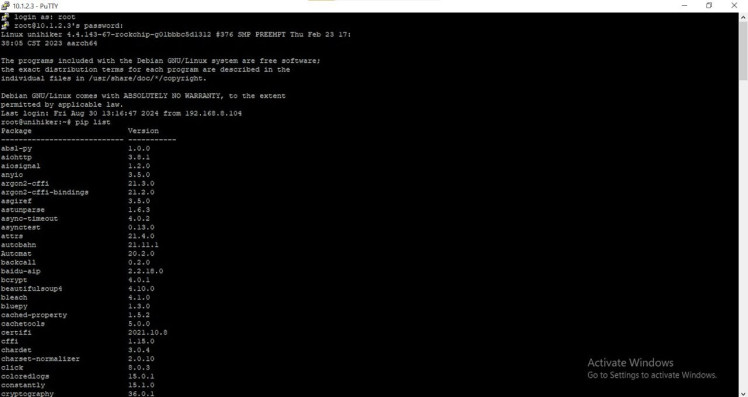
Read on further to learn about each important libraries that we will be using in this project and find the instructions on how to install them. Only install the packages if they are not available in your list of installed Python packages. If they are available, you can choose to upgrade them by running the following command:
pip install --upgrade <Package-name>Tesseract OCR
Tesseract is an open-source and highly popular optical character recognition (OCR) engine. It was originally developed by Hewlett Packard, and is currently sponsored by Google.
We will be using Tesseract v4 which includes a highly accurate deep learning based model for text recognition, and supports over 100 languages. Unfortunately, there are some limitations to this OCR solution. It works best on high quality images and can only recognize clear and basic font.
There are better OCR solutions like EasyOCR and KerasOCR but I chose this instead because, as far as I know, this is the only OCR solution that works normally on the UNIHIKER.
The following versions of Tesseract has added support for our required languages:
- Tesseract v1: English
- Tesseract v2: Added support for French, German, and Spanish
- Tesseract v3: Added support for Chinese
- Tesseract v4: Added support for Korean and Tamil
This is the reason why we need Tesseract v4.
Now let's install the tesseract ocr Python package and the required language packs. Run the following commands in PuTTY:
pip install pytesseract
sudo apt-get install tesseract-ocr-fre
sudo apt-get install tesseract-ocr-deu
sudo apt-get install tesseract-ocr-spa
sudo apt-get install tesseract-ocr-chi-sim
sudo apt-get install tesseract-ocr-kor
sudo apt-get install tesseract-ocr-tam
OpenCV
OpenCV is the world's largest and most comprehensive open-source computer vision library. It offers a wide range of tools and functionalities for computer vision, machine learning, and image processing. With its extensive collection of algorithms and utilities, OpenCV is a powerful resource for developing advanced applications in these fields, making it a go-to choice for both research and real-world projects.
We will need this library to capture the image using our webcam before we can pass it on to the OCR model.
There should be an option of OpenCV Python package installed on your UNIHIKER as one of the demo applications uses the library but if you do not have it installed, you can download the required package by running the following command:
pip install opencv-contrib-pythonInformation from Opencv-contrib-python - PyPi

Information from Opencv-contrib-python - PyPi
It is important that only one OpenCV package exists on your device to avoid further confusions and errors.
Google Translate API (Googletrans)
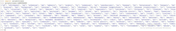
Moving on, we will be installing the Googletrans Python library to translate the text extracted by the OCR into the user's selected language, ensuring that the output is in their preferred language.
This is a free and unlimited Python library that implements Google Translate API. It uses the Google Translate Ajax API to make calls to such methods as detect and translate.
However, there is a limitation on this library usage where the maximum character limit on a single text is 15, 000.
You can install this library by running the following command:
pip install googletransHere is an example using this library (in Python app):
from googletrans import Translator
translator = Translator() # initiate the Google API translator
translation = translator.translate("Hello World", dest = "de") #Translate to german
print(f"{translation.origin} ({translation.src}) --> {translation.text} ({translation.dest})")
The output will be like this:
Hello World (en) --> Hallo Welt (de)Run the following command in Python to view the available languages and the corresponding language codes:
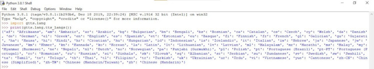
Google Text-to-Speech API (gTTS)
The gTTS (Google Text-to-Speech) is a Python library and command-line interface (CLI) tool that provides an easy way to interact with Google Translate's text-to-speech API. It converts input text into spoken mp3 audio, which can then be saved as a file for later use. This makes it a convenient solution for generating audio output from text data.
You can install the library by running the following command:
pip install gTTSHere is an example of how this library is used (in Python app):
from gtts import gTTS
tts = gTTS('hello')
tts.save('hello.mp3')
Run the following command in Python to view the available languages and the corresponding language codes:
PySerial
The PySerial encapsulates the access for the serial port. This is the library that we will need to receive the data (language choice) sent from the STM32F411 "BlackPill" Development Board.
You can download the library by running the following command:
pip install pyserial2. Connecting to Bluetooth devices [PuTTY]
The UNIHIKER comes equipped with built-in Bluetooth connectivity, enabling connections to other Bluetooth devices. It is now time to establish a connection between the UNIHIKER and the HC-06 Bluetooth module, which is linked to the STM32F411 "BlackPill" Development Board. To execute this, run the following command:
rfcomm bind rfcomm0 xx:xx:xx:xx:xx:xx (Device ID)If you do not have the Device ID, you can obtain this during the Bluetooth device scan. Run the following commands in PuTTY to turn on Bluetooth:
bluetoothctl
default-agent
power on
You can scan for nearby Bluetooth devices by running the following command:
scan onAs we will be connecting the Bluetooth earbuds/ speaker, make sure they are in pairing mode. Once you run the command above, a list of the available devices will be shown. Sometimes, the name of the device will also be displayed along with the device ID.
Pair the Bluetooth earbuds/ speaker by running the following command:
trust xx:xx:xx:xx:xx:xx (Device ID)
pair xx:xx:xx:xx:xx:xx  (Device ID)
connect xx:xx:xx:xx:xx:xx (Device ID)
Once the connection is successful, the message will be displayed and you are good to go. Do not close PuTTY because the connection will be lost.
Jupyter Notebook
Jupyter Notebook is a web-based interactive computing platform. It supports over 40 programming languages, including Python, R, Lydia, and Scala.
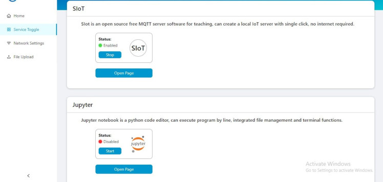
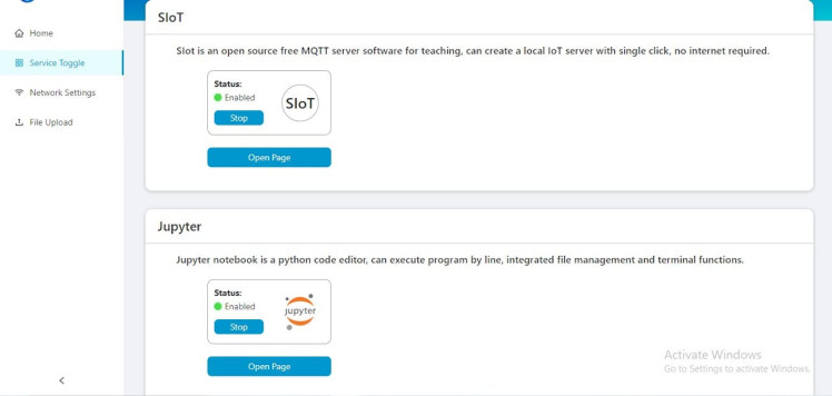
It is in-built in UNIHIKER and is easy to program. To access the Jupyter Notebook, open the local web page menu on UNIHIKER by entering 10.1.2.3 and go to Service Toggle where you can find SIoT and Jupyter. Enable the Jupyter Notebook by clicking on Start and select Open Page.
You can get started by creating a Jupyter Notebook. You start off by importing the required libraries:
import time, serial, os
import cv2
import pytesseract
from pinpong.board import *
from pinpong.extension.unihiker import *
from unihiker import Audio
from PIL import Image
from googletrans import Translator
from gtts import gTTS
Initialize the UNIHIKER by this command:
Board().begin()Now, we will be able to utilize the UNIHIKER's user buttons. The next step is to set up the Bluetooth communication link over the serial interface by opening a serial port so that the UNIHIKER can receive the language choice over the Bluetooth communication. As we have bound the Bluetooth module to our UNIHIKER, we can use its port address to establish the serial connection.
The following line of code initializes a Translator object from the googletrans library, specifically configuring it to use the translate.googleapis.com service URL to perform translations:
translator = Translator(service_urls=['translate.googleapis.com'])This setup can ensure more reliable access to Google Translate, especially in cases where the default URL might not work optimally.
Next step is to instantiate the Audio object so that we can play the 'system' audio files to make this Third eye device as a user friendly device.
audio = Audio() #Instantiate the Audio objectYou have to specify the path to the Tesseract OCR engine executable to prevent any errors when using the pytesseract library. To do this, try:
pytesseract.pytesseract.tesseract_cmd = r'/usr/bin/tesseract'This will configure pytesseract to use the Tesseract executable located at /usr/bin/tesseract for performing OCR tasks.
Next, we will have to develop a function designed to handle the data transmitted over the Bluetooth connection. This function will extract and return the language code in a string format. Language codes are crucial for the system to specify the language of the text that is going to be processed by the OCR, determine the language in which the text should be read aloud, and specify the target language for the translations.
The language codes required by the pytesseract are in three-letter format, unlike the ones required by gTTS and googletrans, so we have to kind of map the output of the language function to the corresponding language code which can then be passed on to pytesseract.
Create a function called image_capture to ensure the existence of the directory, save the given image source to the specified directory (/root/image/pic/), and then return the image as a PIL image object. If an error occurs during the directory creation or image saving, it should play the error.wav file, release the camera, and close any OpenCV windows.
The image captured by the webcam and the "mapped" language code should be used to run the OCR solution and return the text in string type. This text output from the OCR and language code should be input to the translate function and then the translated text can be converted into speech, saved it as an audio file, and then played back to the user. This function should be programmed to provide feedback to the user by playing the Translating.wav sound at the start.
Similarly to the previous function, the next function should take the OCR's text output and the user's specified language code as inputs, convert the text into speech using the Google Text-to-Speech service, save the spoken version as an audio file, and then play the audio file for the user. The function should also provide feedback by playing the Reading.wav file at the start, signaling that the text-to-speech process is in progress.
The following set of code ensures that the video capture is correctly initialized and displayed in full-screen mode while providing feedback through sounds in case of errors or specific events:
cap = cv2.VideoCapture(0)
cap.set(cv2.CAP_PROP_BUFFERSIZE, 1)
cv2.namedWindow('cvwindow',cv2.WND_PROP_FULLSCREEN)
cv2.setWindowProperty('cvwindow', cv2.WND_PROP_FULLSCREEN, cv2.WINDOW_FULLSCREEN)
while not cap.isOpened():
    audio.play("Cam_error.wav")
    continue
buzzer.pitch(1000,1)
The code should be programmed to run in a loop, continuously process the real-time video feed from the webcam and adjust it to fit the screen while awaiting user input. When the user presses Button A, the device should capture an image and prompt the user to specify the language of the text in the image. The identified language should then be used by the OCR solution to process the text, which will subsequently be read aloud.
Alternatively, if the user presses Button B, the image should be captured, and the device should be programmed to wait for the user's response where the user has to choose the language of the text present in the captured image. This is helpful in situations where the visually impaired individual is trying to read something written in a language they do not understand but know which language it is written in.
The device should take in the user's input and after running the OCR solution, it should prompt the user to select a language of their choice for translation. The googletrans library should be used to translate it into the specified language, and gTTS should be used to convert the translated text into an audio file which can then be played and the translated text should be read out aloud.
If the frame is not successfully read, the loop is broken and the application cleans up and releases the camera:
cap.release()
cap.destroyAllWindows()
Final Look

Basic prototype of the 'Third Eye'

XIAO ESP32S3 Sense and STM32F411 "BlackPill" Development Board

XIAO ESP32S3 Sense and STM32F411 "BlackPill" Development Board

UNIHIKER connected to USB Webcam

UNIHIKER - OCR Solution & Translation
The working videos of this project are posted below, and each video demonstrates each feature of this Third Eye prototype.
Third Eye: Face Recognition Model [XIAO ESP32S3 Sense and STM32F411 "BlackPill" Development Board]
Third Eye: OCR Solution [UNIHIKER and STM32F411 "BlackPill" Development Board]
Third Eye: Translation [UNIHIKER and STM32F411 "BlackPill" Development Board]
Remarks
I have greatly enjoyed working on this project, and Third eye was definitely eye-opening and I learnt a lot. There are some upgrades I plan to implement in the future to further improve and expand the project's capabilities.
I would like to thank Marcelo Rovai for his insightful tutorial (TinyML Made Easy: Object Detection with XIAO ESP32S3 Sense).
I hope you all liked this project.
Schematics, diagrams and documents
Code
Credits
Related products


Leave your feedback...