Temperature & Humidity Monitoring With Blynk Cloud- Esp32
About the project
This tutorial shows how to monitor temperature and humidity from Magicbit (ESP32) and view it in the Blynk cloud dashboard.
Project info
Difficulty: Easy
Platforms: Blynk
Estimated time: 1 hour
License: GNU General Public License, version 3 or later (GPL3+)
Items used in this project
Hardware components
Story
In this tutorial we will provide guidance on how to make a weather station which you can view in your device (laptop/monitor) as a dashboard in Blynk cloud. The sensor module we are using here is the DHT11 sensor module which is connected to the Magicbit and the sensor data will be transferred to the computer.
Theory and methodologyFor this weather station, we hope to collect temperature and humidity data of the surroundings. That purpose we use a DHT11 sensor module that measure those two parameters. Output data from the sensor should be given to the microcontroller which have WIFI adapter to connect with internet. The DHT11 sensor module can be simply plugged into Magicbit development board. Since Magicbit development board is based on the ESP32 processor, it already has the WiFi connectivity as an inbuilt feature to connect to the Internet. After getting the data to the microcontroller, we transfer that sensor data to the cloud platform and we can design a customized interface to view that data. For this purpose, we use the Blynk application. Blynk is an Internet of Things platform with free Cloud, apps and digital dashboard where you can build a graphic interface for your project by simply dragging and dropping widgets. What is more, it supports to many types of processors like Arduino, Esp32 and so on. You can get More details about this app and this online platform by going through following link. Also, we have already done how to do this weather station using Blynk mobile application which you can refer using this link.
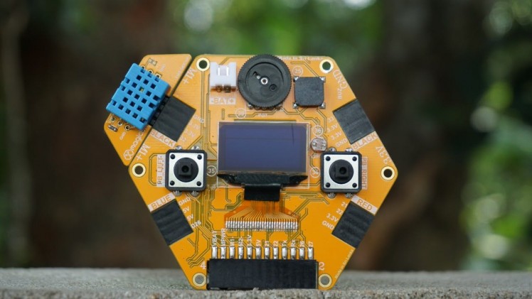
Hardware setupThis is very simple since you are using a magic board! Plug the sensor module to Magicbit here we are connecting it to the D32 pin on the board. Then connect the Magicbit to your computer using the micro-USB cable.
The most work of this project is with setting up the software. In the theory and methodology section, we mentioned that we are using Blynk application to display our data. So, let’s first setup our Blynk dashboard.
- Go to Blynk.io website and the first-time login you might need to create an account giving your email and create any password you want. After the verification you can log in to your workplace. If you already have an account, you can just sign in using the credentials. For more signup details to blynk, visit here.
- Then you will be having a page (or a workplace/organization) as shown in the figure below.
Workplace/organization Tab
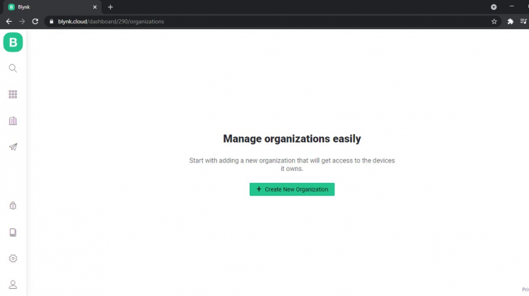
Workplace/organization Tab
- You will have to turn on the developer mode ‘on’ here. By default, first user in the Organization becomes a Developer. Developer is a special user who has access to all the functionality required to configure the platform for the use by end-users. To know more on this, you can visit the link here.
- Navigate to My Profile / User profile in the left menu
- Check that Developer Mode switch is set to ON.
Then you need to create a template. For this, open the Templates section in the left menu and click + New Template button.
New Template creation
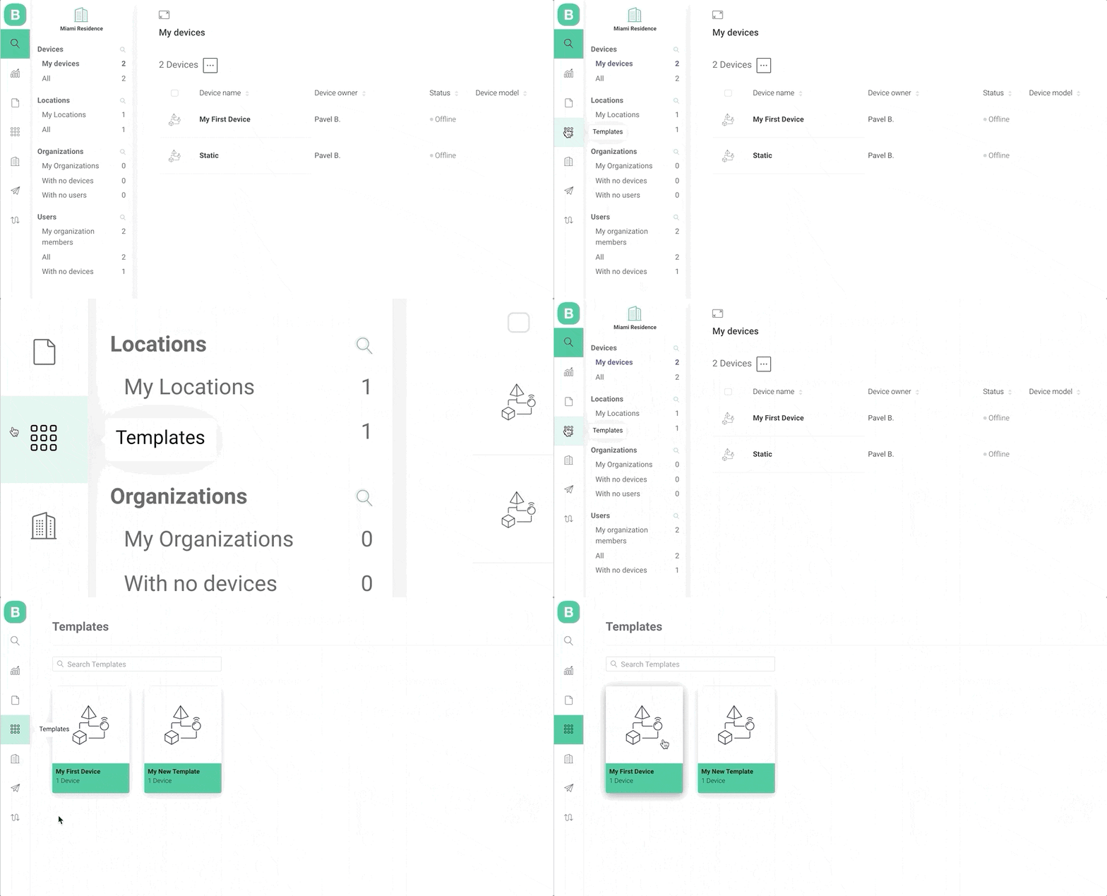
New Template creation
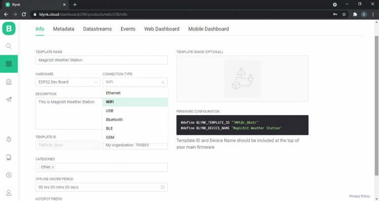
- Give your new template a name, specify the hardware and connectivity you will be using. For this project since we are using the Magicbit, we are selecting the hardware as ESP32 Dev Board and connectivity type as WiFi.
New Template creation
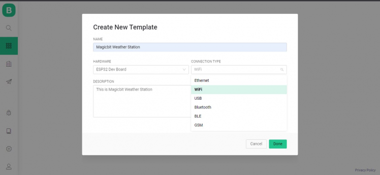
New Template creation
- A new Template is now created. On this screen notice in a black box, Template ID and Firmware Configuration sections. You will need these details later in your sketch.
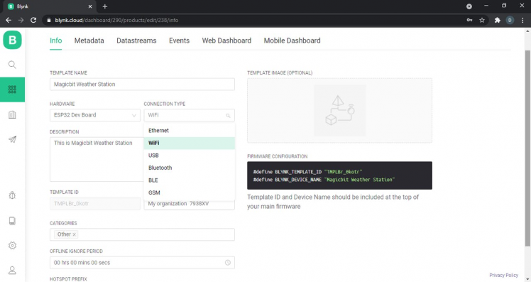
- For the goal of this project skip the Metadata Tab and go directly to Datastreams tab. Let’s now set up our data streams. Datastreams are channels that are used to send data between the device and Blynk.Cloud. We will be using this Datastream to send random values from our device. In this project we represent our data using two analog meters and we show the variation our data with time using graph. Our analog data will be the temperature and humidity readings. So, for this project we need to create two Datastreams.
- Let’s create the temperature datastream. Click on Add Datastream button. Choose Virtual Pin in the dropdown menu:
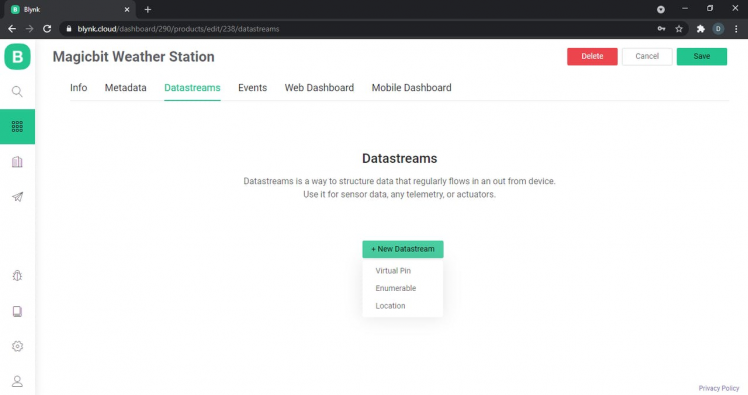
- Set up the Datastream like this:
Name: TemperatureVirtual Pin: V6Data Type: DoubleUnits: CelsiusMin/Max: 0/100
Note that here, V6 means virtual pin 6. This means the application gets data from the virtual pin 6. This is NOT the sixth pin of the ESP32. Virtual 6 pin is only used for communicate between board and application via internet. It is not a real pin.
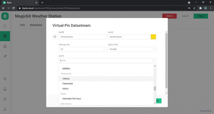
You can skip all the other settings if you want or just change them. When done, press Create and the new Datastream for temperature will be created.

- Then the same way create the datastream for humidity.
Name: HumidityVirtual Pin: V5Data Type: DoubleUnits: PercentageMin/Max: 0/100
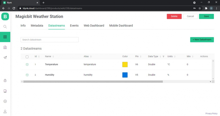
- Note that since the V6 pin is already is already allocated to the temperature stream, we cannot use it here again. You can skip all the other settings if you want. When done, press Create.
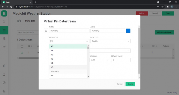
These settings mean that our device that inherit this Template will process temperature and humidity values in the range of 0 to 100 through Virtual Pin V6 and V5 respectively and Blynk will interpret them through a chart that we will create in the next steps. See more on datastreams here.
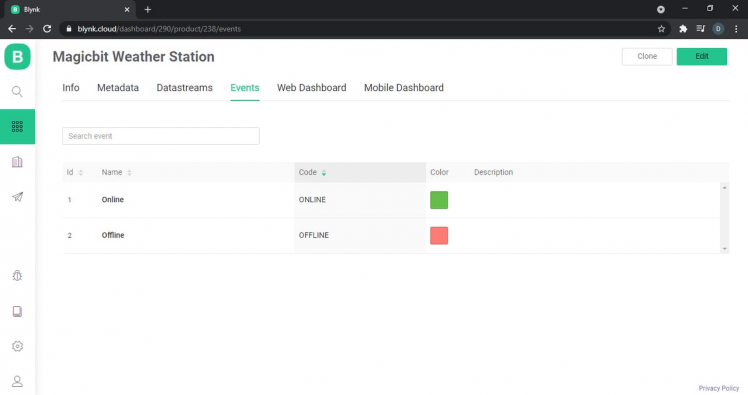
- Then go to the events tab. Events tell the current status of our device whether it is online or offline. Online and Offline events are default system events handled by the server. See more on events here.
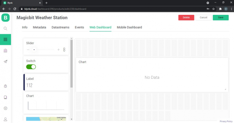
- Now we will create our web dashboard. For this move to the web dashboard tab. Here you can drag-n-drop these widgets to the canvas. You can drag n drop two labels, one for temperature and one for humidity. Then drag and drop a chart too.
- You can rename and change the settings of each of these widgets by clicking the setting icon on the top right corner.

Do not forget to include the respective DataStream as well, like shown in the below images. Also save your template too after all these steps!
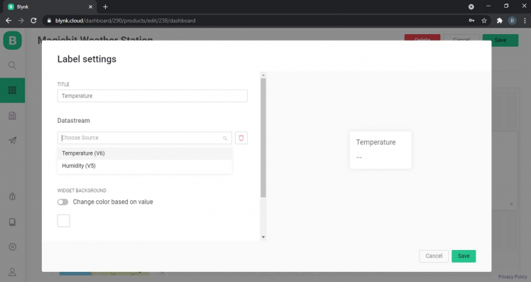
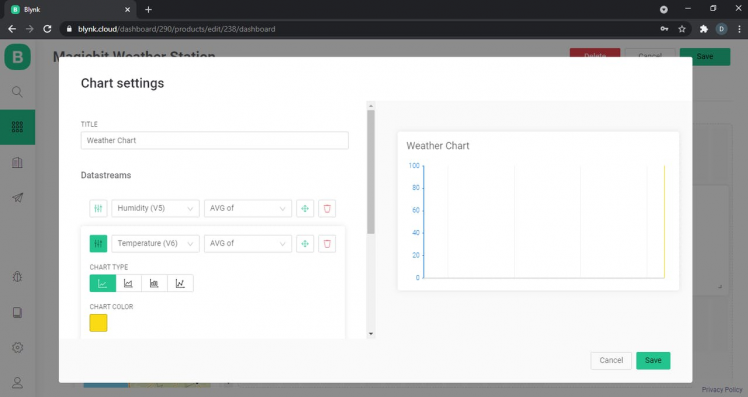
See more details on dashboards here.
- Now we completed the dashboard setting up part. But without uploading the correct source code to Magicbit, we cannot connect with this dashboard. So, let’s look at how to do that.
- We are using Arduino IDE here. At the first stage we include specific libraries for establish internet connection using WIFI. The libraries are already installed to with your Magicbit board in Arduino except Blynk library. So, we need to install Blynk Library for Arduino IDE. There are 3 ways you can do this.
1. Using built-in library manager in Arduino IDE
2. Installing Blynk library as ZIP file in Arduino IDE
3. Manually install Blynk Library
The easiest way is the first one so we will see here how to do that. If you want to follow other two ways instead of this first one you can see how to do it from here.
Install Blynk Library using built-in library manager in Arduino IDE
To install a new library into your Arduino IDE you can use the Library Manager (available from IDE version 1.6.2). Open the IDE and click to the "Sketch" menu and then Include Library > Manage Libraries.
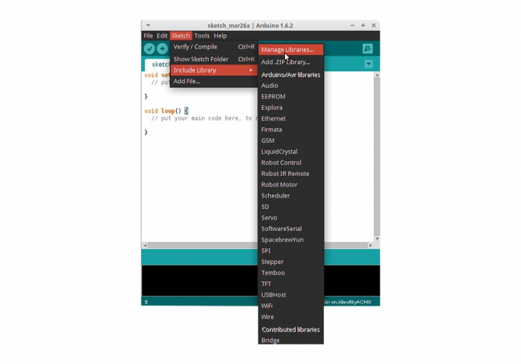
- Then the Library Manager will open and you will find a list of libraries that are already installed or ready for installation. Search for Blynk library and in the version, selection choose the latest version to date.
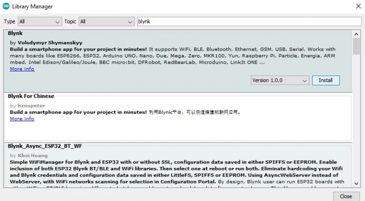
Finally click on Install and wait for the IDE to install the new library. Downloading may take time depending on your connection speed. Once it has finished, an Installed tag should appear next to the Bridge library. You can close the library manager.
You can now find the new library available in the Sketch > Include Library menu.
- Next, we have to do the device activation part to connect it to the WiFi. So, we will activate our device with a Static Auth Token.
- For this you need to get the template ID and auth token for device. Go to the info tab of your created template. Copy the contents of the black section and paste them to your Arduino sketch.
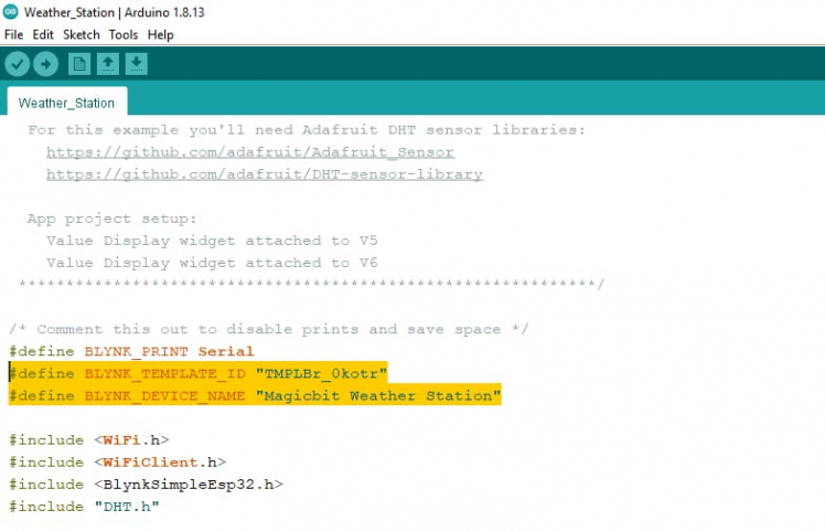
- Then we need to get our Auth token. When the Template is ready, go to Search -> Devices - Create new device. Choose a Template and give your new device a name.
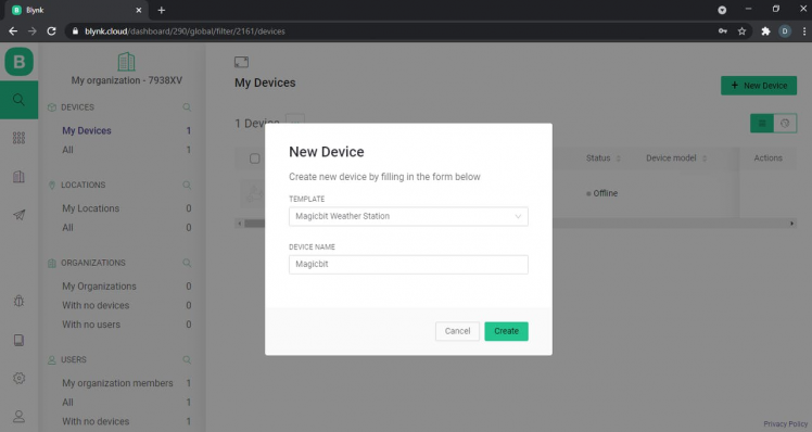
After the device was created, open its dashboard, go to the Device Info tab. There you will find a field: Auth Token.
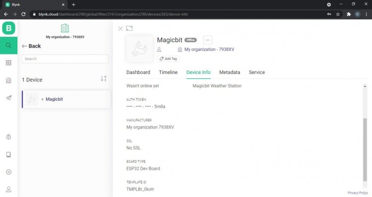
Copy that auth token and paste it in the code.
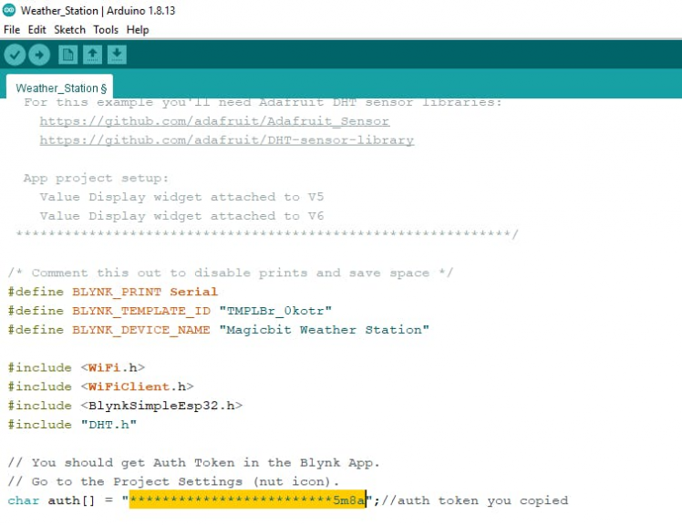
- Check where our sensor is connected to the Magicbit. In this case the connected pin is 32. In the setup you can see there are two virtual pins. Set those pins as V5 and V6. If you used different pins in the dashboard then change that in code accordingly. When the code is running in the processor, first it connects to WIFI. Then transmits the data via Internet through V5 and V6. This is looping process. Now select correct com port and select board type as Magicbit.
- Now you are all done and you can the code to the board.
After uploading the code successfully, the Magicbit board will connect to your WIFI automatically. According to your connection condition the process can be faster or slower.
You will see the device becomes online in the dashboard as well.
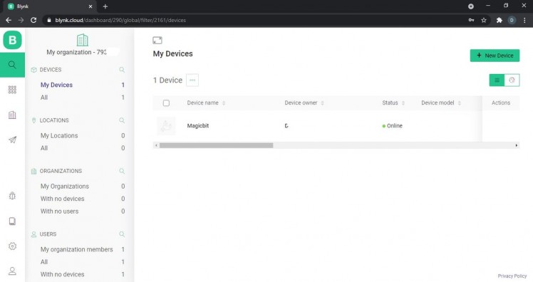
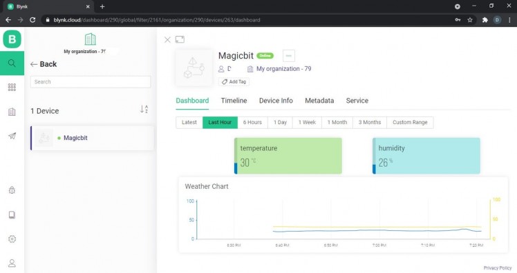
- Now go to your project in Blynk app and it’s time to check your dashboard. If your app is connected with your board via Internet, then you will be able to see the details getting and drawing in the chart. Nice, Its working! Now you can see temperature and humidity from the dashboard.
- If you didn’t get any data once connected. Then,



Leave your feedback...