I2c 7-segment Display With attiny85
About the project
An I2C device that uses common anode 7-segment displays.
Project info
Difficulty: Moderate
Platforms: Arduino, Microchip, Texas Instruments
Estimated time: 1 day
License: GNU General Public License, version 3 or later (GPL3+)
Items used in this project
Hardware components
Story
0. Intro
Because I had a bunch of common anode 7-segment displays I decided learn how to make I2C slave device.
Originally published on https://taunoerik.art/portfolio/selfmade-i2c-7-segments-display-with-attiny85/
1. 7-segment LEDs
My 7-segment LEDs are marked as 5611BH and looks like this:
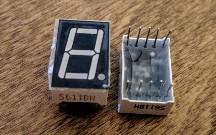 5611BH common anode 7- segment LED
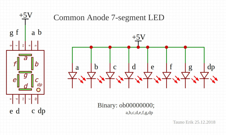 Common anode 7-segment LED circuit.
2. 7-segment LEDs module
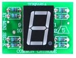
I connected four 7-segment displays together on PCB and I added resistors (470Ω).
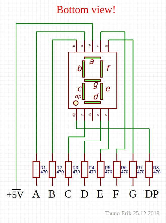 One 7-seg LED with resistors
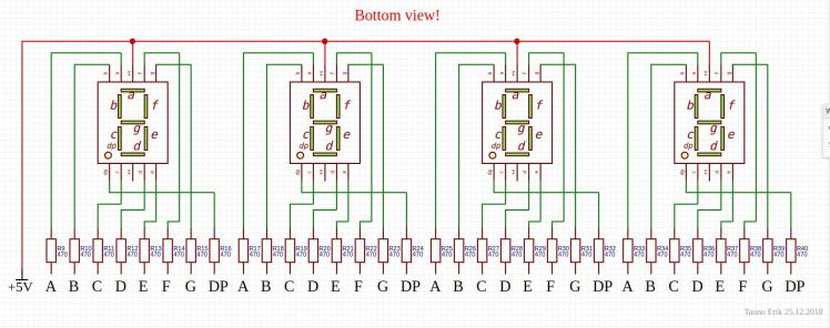 All four 7-segment LEDs connected together
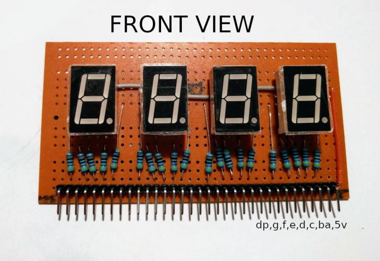 LED module front view
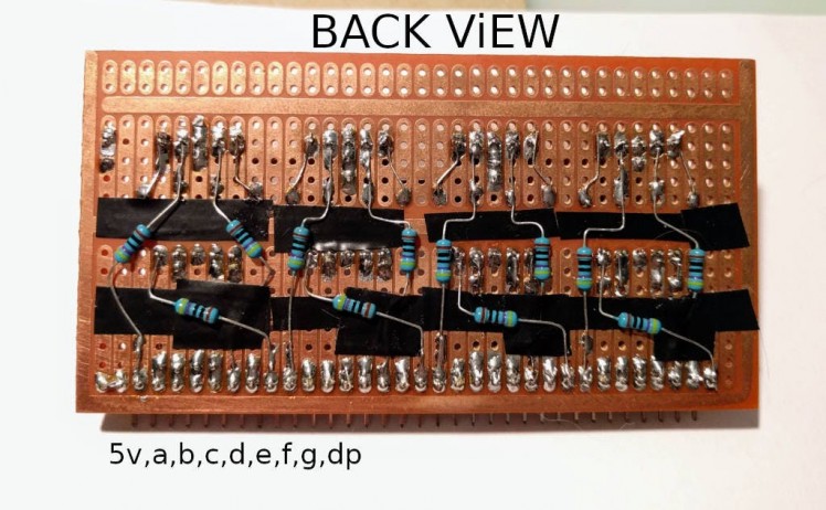 LED module back view
3. Shift registers module
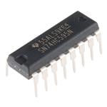
I use 74HC595 shift registers to drive 7-segment LEDs.
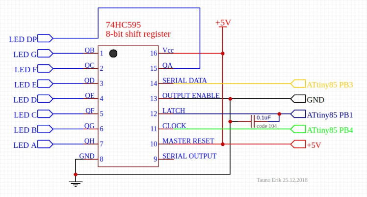 One 74HC595 Shift register
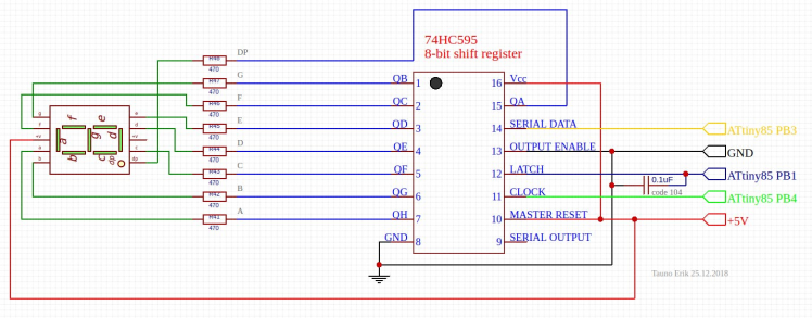 7-segment LED + 74HC595 Shift Register
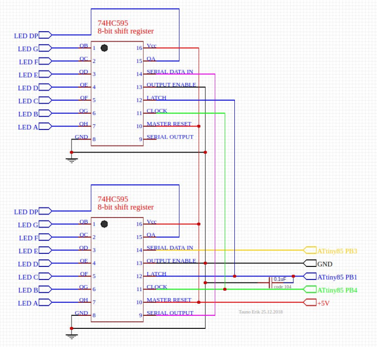 Connecting multiple 74HC595 shift registers together.
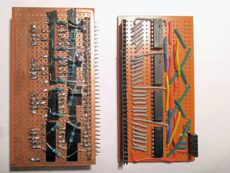 LED module + 74HC595 Shift Register module
4. ATtiny85 module
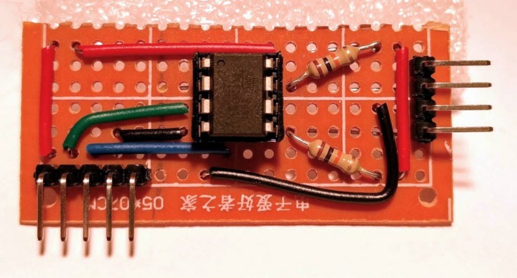
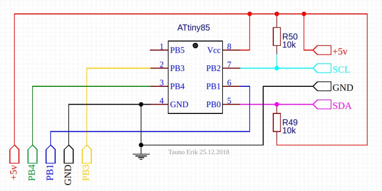 ATtiny85 module
5. Master Code
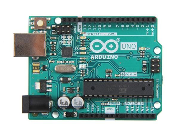
Example master (Arduino Uno or Nano) code:
#include
int output = 1234;
void setup() {
 Wire.begin(); // join i2c bus
 Serial.begin(9600);
}
void loop() {
 byte iiii = (output/1000) % 10; // == 1
 byte  iii = (output/100) % 10;  // == 2
 byte   ii = (output/10) % 10;   // == 3
 byte    i = output % 10;        // == 4
 Wire.beginTransmission(10); // transmit to device #10
 Wire.write(iiii);   // sends one byte
 Wire.write(iii);
 Wire.write(ii);
 Wire.write(i);
 Wire.endTransmission(); // stop transmitting
 Serial.println(output);
 Serial.println(iiii);
 Serial.println(iii);
 Serial.println(ii);
 Serial.println(i);
 output++;
 delay(1000);
 if(output > 9999){
   output = 0001;
 }
} //loop end
6. Programming ATtiny85
Look my tutorial: Programming ATtiny85 with Arduino Uno
Download and install TinyWire libary: https://github.com/lucullusTheOnly/TinyWire
7. Slave code
Example slave (ATtiny85) code:
/*
* Chip: ATtiny85
* ATtiny85 as i2c Slave Receiver
* Date: 23.12.2018
* Author: Tauno Erik
*/
#include
byte own_address = 10; //Slave i2c address
// Arduino uno: latch 8, data 11, clock 12
// ATtiny PB1, PB3, PB4
int latchPin = 1; // Pin connected to ST_CP of 74HC595
int dataPin  = 3; // Pin connected to    DS of 74HC595
int clockPin = 4; // Pin connected to SH_CP of 74HC595
// Array holds digits 0-9
byte numArray[11];
uint8_t    i = 0;
uint8_t   ii = 0;
uint8_t  iii = 0;
uint8_t iiii = 0;
void setup() {
 // Setup TinyWire I2C slave
 TinyWire.begin( own_address );
 // Sets callback for the event of a slave receive
 TinyWire.onReceive( onI2CReceive );
 // Set pins to output because they are addressed in the main loop
 pinMode(latchPin, OUTPUT);
/*
* 7-segment LED:
*  |--A--|
*  F     B
*  |--G--|
*  E     C
*  |--D--|
*         H
*
*  GF+AB
*    #
*  ED+CH
*
*  0b00000000
*    ABCDEFGH
*
*  0- High! (Common anode!)
*  1- Low
*/
  numArray[0] = 0b00000011;
  numArray[1] = 0b10011111;
  numArray[2] = 0b00100101;
  numArray[3] = 0b00001101;
  numArray[4] = 0b10011001;
  numArray[5] = 0b01001001;
  numArray[6] = 0b01000001;
  numArray[7] = 0b00011111;
  numArray[8] = 0b00000001;
  numArray[9] = 0b00001001;
 numArray[10] = 0b11111111; // all off
 digitalWrite(latchPin, 0);
 shiftOut(dataPin, clockPin, 0b11111110);
 shiftOut(dataPin, clockPin, 0b11111110);
 shiftOut(dataPin, clockPin, 0b11111110);
 shiftOut(dataPin, clockPin, 0b11111110);
 digitalWrite(latchPin, 1);
 delay(400);
} //setup end
void loop() {
} //loop end
/**********************************************************************
* I2C Slave Receive Callback:
* Note that this function is called from an interrupt routine and shouldn't
* take long to execute
**********************************************************************/
void onI2CReceive(int howMany){
 digitalWrite(latchPin, 0);
 //while(TinyWire.available()>0){
 while(1 < TinyWire.available()){
    int c = TinyWire.read();
   shiftOut(dataPin, clockPin, numArray[c]);
 }
 //lastone
 int x = TinyWire.read();
 shiftOut(dataPin, clockPin, numArray[x]);
 digitalWrite(latchPin, 1);
}
/********************************
*
********************************/
void numsOut(int i, int ii, int iii, int iiii){
 digitalWrite(latchPin, 0);
 shiftOut(dataPin, clockPin, numArray[iiii]); //0xxx
 shiftOut(dataPin, clockPin, numArray[iii]);  //x0xx
 shiftOut(dataPin, clockPin, numArray[ii]);   //xx0x
 shiftOut(dataPin, clockPin, numArray[i]);    //xxx0
 digitalWrite(latchPin, 1);
 }
/*************************************
*
*************************************/
void shiftOut(int myDataPin, int myClockPin, byte myDataOut) {
 // This shifts 8 bits out MSB first,
 // on the rising edge of the clock,
 // clock idles low
 //internal function setup
 int i=0;
 int pinState;
 pinMode(myClockPin, OUTPUT);
 pinMode(myDataPin, OUTPUT);
 //clear everything out just in case to
 //prepare shift register for bit shifting
 digitalWrite(myDataPin, 0);
 digitalWrite(myClockPin, 0);
 //for each bit in the byte myDataOut�
 //NOTICE THAT WE ARE COUNTING DOWN in our for loop
 //This means that %00000001 or "1" will go through such
 //that it will be pin Q0 that lights.
 for (i=7; i>=0; i--)  {
   digitalWrite(myClockPin, 0);
   //if the value passed to myDataOut and a bitmask result
   // true then... so if we are at i=6 and our value is
   // %11010100 it would the code compares it to %01000000
   // and proceeds to set pinState to 1.
   if ( myDataOut & (1<<i) ) {
     pinState= 1;
   }
   else {
     pinState= 0;
   }
   //Sets the pin to HIGH or LOW depending on pinState
   digitalWrite(myDataPin, pinState);
   //register shifts bits on upstroke of clock pin
   digitalWrite(myClockPin, 1);
   //zero the data pin after shift to prevent bleed through
   digitalWrite(myDataPin, 0);
 }
 //stop shifting
 digitalWrite(myClockPin, 0);
}






Leave your feedback...