


Rotating Led Sphere – A Rp2040 Pov Display Step By Step
About the project
Inspired by the Las Vegas Sphere, this project brings the concept to desktop scale: a spherical POV LED display powered by an RP2040. It plays videos and animations from an SD card, runs wirelessly, and can be controlled via Wi-Fi. A key goal was to achieve stunning visuals using as few components as possible. Fully open source.
Project info
Difficulty: Difficult
Platforms: Arduino, Autodesk, Raspberry Pi, JLCPCB, PlatformIO
Estimated time: 1 week
License: Creative Commons Attribution-NonCommercial CC BY-NC version 4.0 or later (CC BY-NC 4+)
Items used in this project
Hardware components
Story
Introduction
Persistence of Vision (POV) displays have always fascinated me. With just a few components and clever timing, they can create incredibly impressive visual effects that seem almost magical. They're also a perfect playground for anyone into electronics, microcontrollers, and creative coding, because they combine hardware, software, and timing in such a hands-on way.
Over the past few years, I’ve developed a whole series of POV displays.
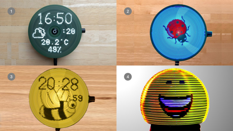
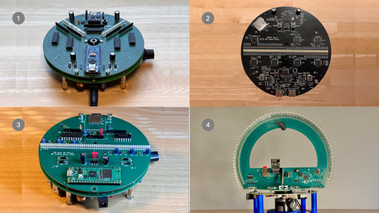
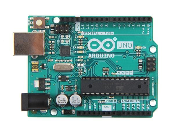
It started with a monochrome version using an Arduino Nano (1), followed by a full-color display driven by an RP2040 (2). That version used 56 RGB LEDs – which looked great, but required quite a bit of complex wiring and electronics.
So I began looking for smarter ways to control a larger number of LEDs with less hardware overhead. That led me to develop the Rotating Display Pico (3), where I first experimented with high-speed LED multiplexing.
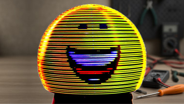
That experiment laid the foundation for this project: the Rotating LED Sphere (4).
Inspired by the massive Las Vegas Sphere, I wanted to create a spherical POV display that could:
How the Display Works
Let’s take a look at how the Rotating LED Sphere processes and displays images, animations, and videos.
At the heart of the system is a microSD card, which stores all visual content. As soon as the display is powered on, it automatically scans the SD card and generates a playlist from all available files. This playlist is then played back in a loop, one item after the other.
To create compatible image data, I’ve developed a conversion tool that runs on a standard PC.
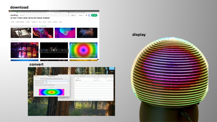
It supports common media types like:
These are converted into a custom .rs64 format optimized for the display’s unique structure and timing. Once converted, the files are simply copied onto the SD card—ready to play.
There are countless free and royalty-free sources for visual content online, but of course, you can also create your own animations. In fact, I’ve found ChatGPT to be a surprisingly helpful assistant when brainstorming visuals or generating simple animation code.
For added convenience, there’s also an optional remote control feature.
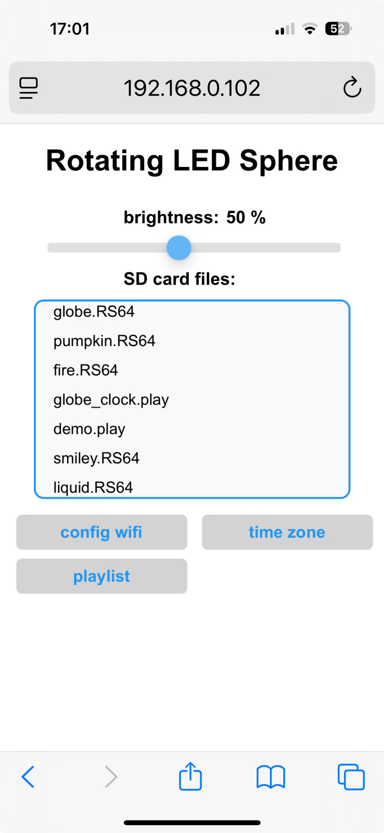
An ESP01s Wi-Fi microcontroller can be plugged into the board, allowing you to access a web-based user interfacevia your local network. This makes it easy to change settings, select content, or manage playlists without touching the hardware.
Understanding the Hardware – How It's All Connected
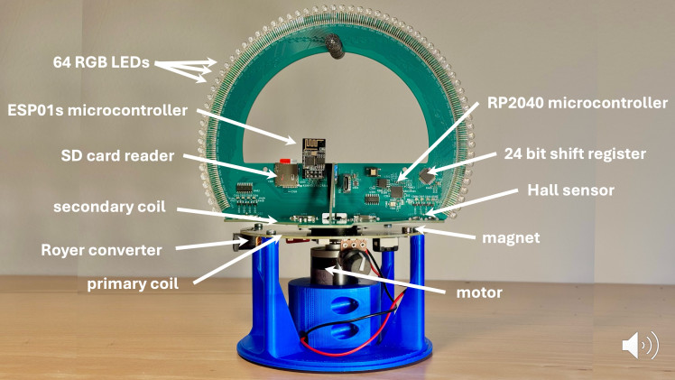
This image gives you a detailed look at the internal structure of the Rotating LED Sphere, highlighting all major functional components. Let’s break it down:
Parts and Preparation
Before we start assembling the Rotating LED Sphere, let’s take a look at all the parts you'll need.
The project is made up of two main groups of components:
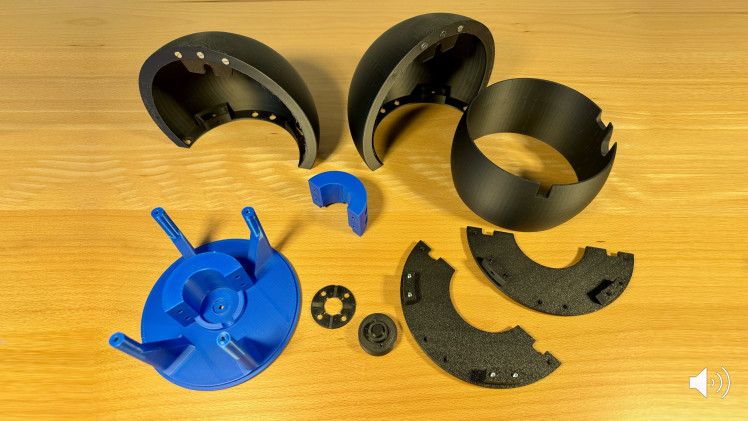
🔷 1. 3D-Printed Plastic Parts
All mechanical components—including the base, support structures, and the sphere housing—are 3D printed. Most parts have been designed in a way that they can be printed without support, which makes the process fast and material-efficient.
Exception:
The two black dome halves do require support material due to their overhanging geometry.
Important note:
Some parts (like the base and LED holder) require inserted M2 or M3 nuts during printing.
You’ll need to pause the print at specific layers to insert the nuts before the rest of the part is completed. This ensures strong mechanical connections later.
All STL files are included in the GitHub repository.
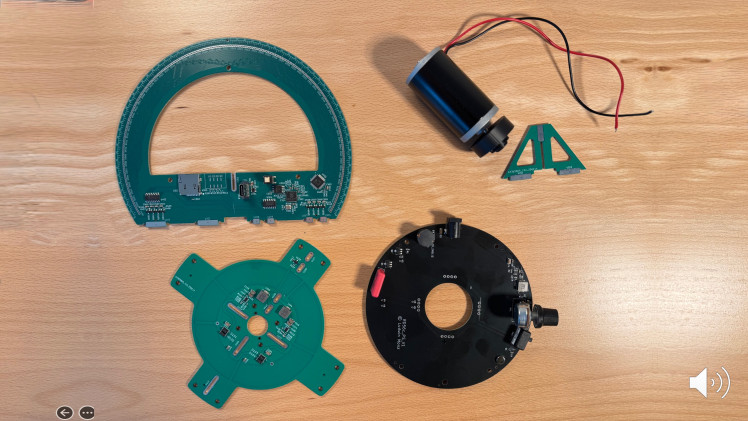
🔶 2. Electronic Components
The electronic system is based on a set of custom-designed PCBs. These include:
Most of the components are SMD (surface-mounted) with small pitch and require precise soldering.
Therefore, it's strongly recommended to have them assembled by a PCB service provider, such as JLCPCB, which offers both fabrication and SMD assembly at reasonable cost.
All KiCad PCB files and the production files are included in the GitHub repo and ready for upload to manufacturing services.
Assembling the Motor Base and Power Supply

This step covers the construction of the device’s base, including the motor mount and wireless power system.
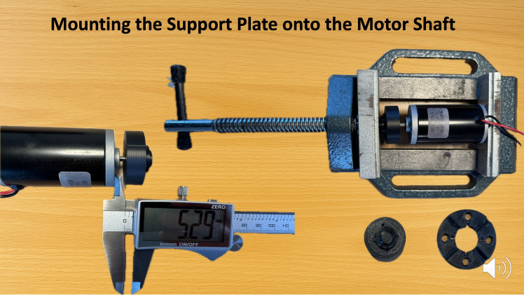
🔸 Mounting the Support Plate
The support plate for the rotating electronics is pressed onto the motor shaft.
Because it has a tight fit by design, you’ll need a bench vise or a clamp to press it in cleanly and evenly.
Use a caliper to ensure the correct distance from the motor housing—this will be important later for rotor balancing and alignment.
🔹 Base Assembly
All components in the base are fixed using standard M3 screws and pre-inserted nuts.
Preparing and Soldering the LEDs
The next step is to prepare and install the 64 RGB LEDs that form the display ring. Since the LEDs are through-hole components with a tight spacing (1.27 mm pitch), proper alignment and clean soldering are essential for reliable operation and a neat result.
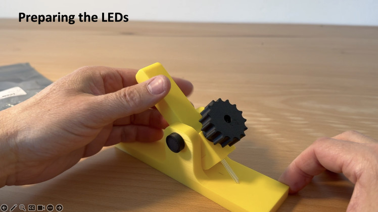
🟡 LED Bending Tool
To make sure each LED sits perfectly on the board, I use a 3D-printed bending jig. The LED is inserted into the guide, and then bent precisely at the correct distance using a lever mechanism.
This ensures that all four pins are aligned and shaped consistently—something that really helps during the soldering process.
You can find the STL file for the tool in the GitHub repository if you'd like to print your own.
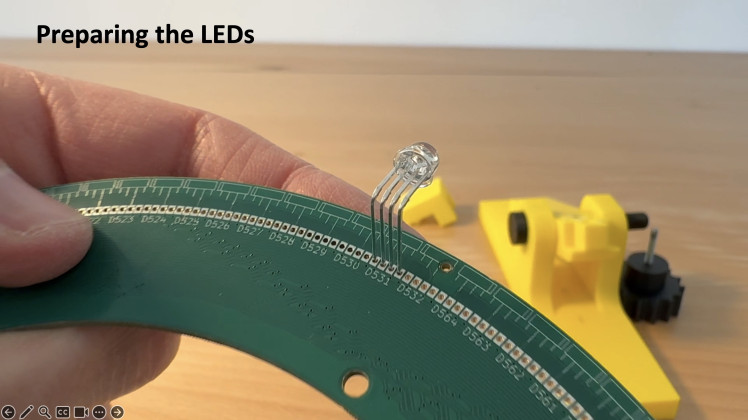
🟢 Inserting the LEDs
After bending, each LED is inserted into the PCB. Take care to follow the orientation markings on the board—especially since the left and right sides of the ring are mirrored (due to the interlaced layout of the display).
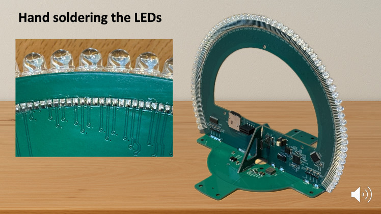
🔧 Hand Soldering
Now it's time to solder. Due to the small pitch, you’ll want to work with a fine-tipped soldering iron, steady hands, and (ideally) some magnification.
Make sure to:
It’s not a fast job, but taking your time here will pay off with a beautiful, functional result.
Rotor Assembly and Alignment

This step involves assembling the rotating structure and carefully aligning it for smooth operation and accurate image rendering.
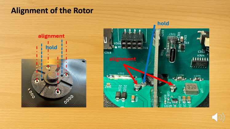
🎯 Aligning the Rotor
Proper alignment is crucial to:
The goal is to bring the symmetry axis of the LED ring into perfect alignment with the rotational axis of the motor.
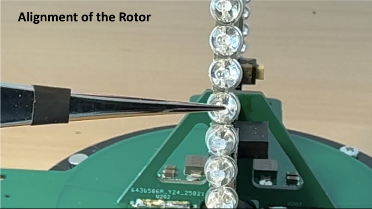
🔧 Step 1 – Mechanical Centering
Mount the LED ring onto the support plate using four adjustment screws and two mounting screws.
The adjustment screws allow you to fine-tune the tilt of the board while you can fix the position with the mounting screws.
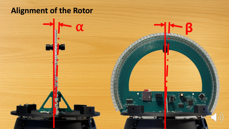
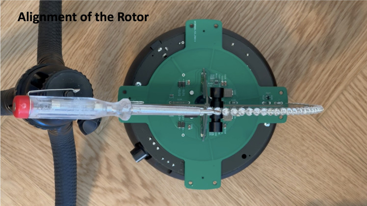
📐 Step 2 – Adjusting the Angles α and β
Take your time with this step—minor adjustments can make a major difference in stability and visual quality.
More details on the alignment process are shown in the accompanying video tutorial.
Attaching the Casing Shells
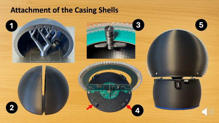
The final mechanical step is the installation of the rotor housing.
The two hemispherical 3D-printed shell parts are attached to the rotating LED structure using M3 screws (🔩 see image). These parts complete the spherical shape of the display and help to reduce the impact of ambient light, significantly improving visual contrast.
💡 Note: One of the shell parts must remain unmounted until:
This concludes the assembly process!
Uploading the Software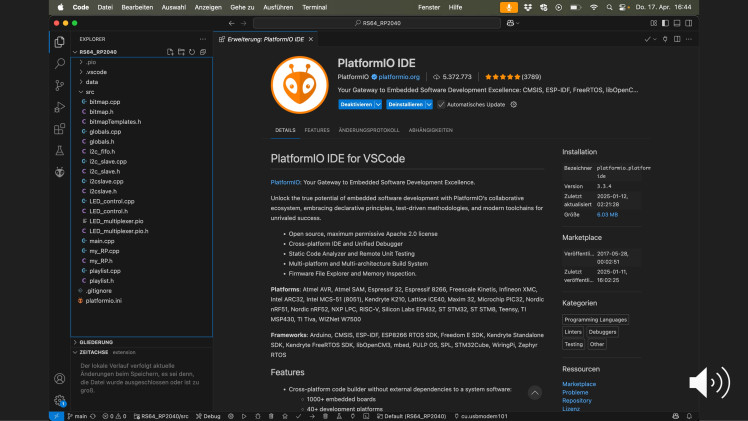
With the hardware fully assembled, it’s time to bring your Rotating LED Sphere to life by uploading the necessary firmware to both microcontrollers: the RP2040 and the optional ESP01s (for wireless control).
🛠️ Development Environment
The software was developed using Visual Studio Code in combination with the PlatformIO extension. This setup offers a professional and beginner-friendly environment to build and upload firmware.
📥 Step-by-Step: Getting the Source Code
🔌 Uploading to the RP2040
📡 Uploading to the ESP01s (optional)
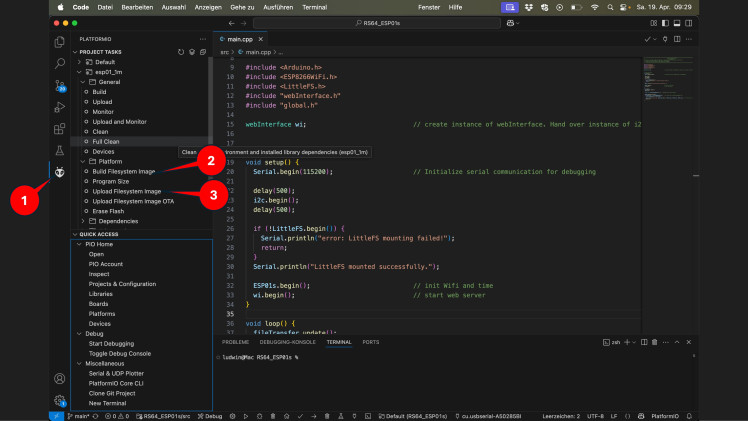
🗂️ Flashing Web Files to ESP01s (LittleFS)
After uploading the firmware, you’ll also need to load the web UI files into the ESP01s's internal filesystem (LittleFS):
That’s it! 🎉 Your LED sphere is now fully programmed and ready to light up.
Preparing the SD Card
The final step before powering up your Rotating LED Sphere is setting up the SD card with the display content.
📁 File Structure
The display scans the top-level directory of the SD card and automatically creates a playlistfrom all .RS64 files it finds.
To enable auto-play on startup, simply copy your .RS64 files directly into the root folder of the SD card (not in subfolders).
▶️ Ready-to-Use Demo Files
As a quick starting point, use the .RS64 files included in the main GitHub repository.
These give you instant feedback and let you verify that everything is working as expected.
🎨 Creating Your Own Content
You can create custom animations and convert them into .RS64 format using the RS64_Converter tool, available in this separate repository:
Here’s what you need:
💻 Platform Support
Once you’ve copied the .RS64 files to the SD card and inserted it into the display, you're ready to hit the power button and enjoy your spinning pixel art!
Wrap-Up & Final Thoughts
Congratulations — you've just completed the Rotating LED Sphere!
This project brings together the best of electronics, programming, mechanical design, and visual art in a compact, mesmerizing display. Whether you’re showing off colorful patterns, looping GIFs, or even full videos, the result is always eye-catching.
🔧 What You’ve Built:
💡 What You’ve Learned:
🚀 What’s Next?
Now that you’ve built the base system, you might explore:
This project is fully open source. Feel free to fork it, remix it, or improve it — just be sure to credit the original source and keep it non-commercial (as per CC BY-NC-SA 4.0).
🙌 Thank You!
If you enjoyed this build, please consider:
Happy making — and keep those LEDs spinning!
Credits
Related products


g