


Remote Control A Linear Actuator With Visuino & Arduino

Made by Ron / Home Automation / Robotics / IoT
About the project
Learn how to remotely control a 12V linear actuator using a 433MHz RF module, Arduino Uno, and Visuino!
Project info
Difficulty: Easy
Platforms: Arduino, SparkFun, Visuino
Estimated time: 1 hour
License: GNU General Public License, version 3 or later (GPL3+)
Items used in this project
Hardware components

Story
In this step-by-step tutorial, we’ll use an L298N motor driver to control the actuator’s movement with ease. Perfect for DIY automation projects.
If you press the top-right or the top-left button the actuator will move fully to one direction, If you press the bottom-right or the bottom-left button the actuator will move to one direction only for the time that you press the button.
Watch the video!
Step 1: What You Will Need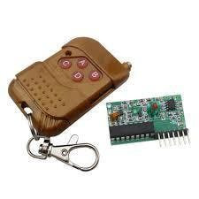
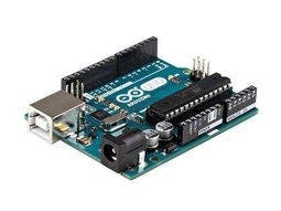
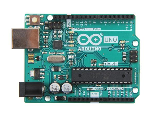
- Arduino UNO (Or any other Arduino)
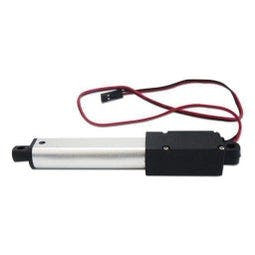
- Linear Actuator
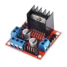
- LN298N DC Motor Driver
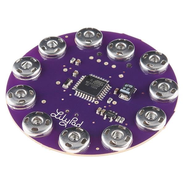
- 433 MHz RF module
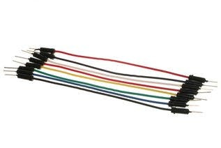
- Jumper wires
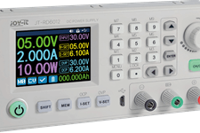
- Power Supply
- Visuino program: Download Visuino
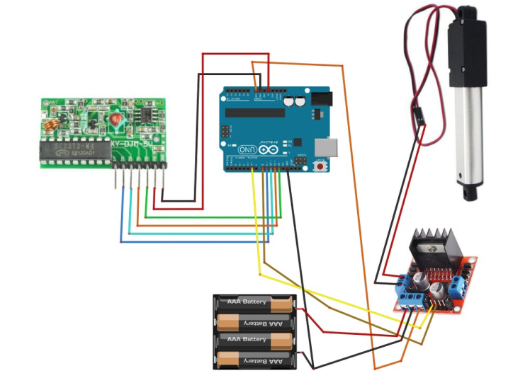
- Connect Remote pin [VCC] to Arduino pin [5V]
- Connect Remote pin [GND] to Arduino pin [GND]
- Connect Remote pin [D0] to Arduino digital pin [4]
- Connect Power supply (batteries) pin (gnd) to motor driver controler pin (gnd)
- Connect Power supply (batteries) pin (+) to motor driver controler pin (+)
- Connect Power supply (batteries) pin (+) to Arduino pin (VIN)
- Connect GND from Arduino to motor driver controler pin (gnd)
- Connect digital pin(6) from Arduino to motor driver pin (IN1)
- Connect digital pin(8) from Arduino to motor driver pin (IN2)
- Connect Linear Actuator to the motor driver as you can see on the schematic
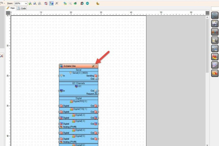
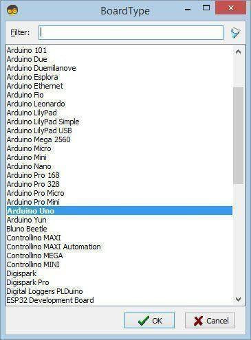
Start Visuino as shown in the first picture Click on the "Tools" button on the Arduino component (Picture 1) in Visuino When the dialog appears, select "Arduino UNO" as shown on Picture 2
Step 4: In Visuino Add Components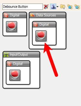
- Add 4X "Debounce Button" component
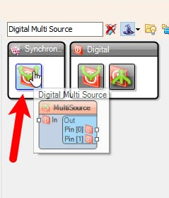
- Add 2X "Digital Multi Source" component
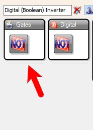
- Add "Digital (Boolean) Inverter (Not)" component
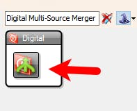
- Add 3X "Digital Multi-Source Merger" component
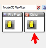
- Add 2X "Toggle(T) Flip-Flop" component
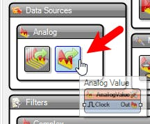
- Add "Analog Value" component
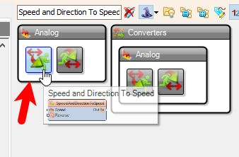
- Add "Speed and Direction To Speed" component
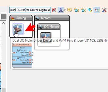
- Add "Dual DC Motor Driver Digital and PWM Pins Bridge (L9110S, L298N)" component
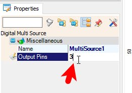
- Select "MultiSource1" and in the properties window set "Output Pins" to 3
- Select "MultiSource2" and in the properties window set "Output Pins" to 3
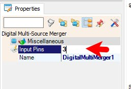
- Select "DigitalMultiMerger1" and in the properties window set "Input Pins" to 3
- Select "DigitalMultiMerger2" and in the properties window set "Input Pins" to 3
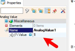
- Select "AnalogValue1" and in the properties window set "Value" to 1
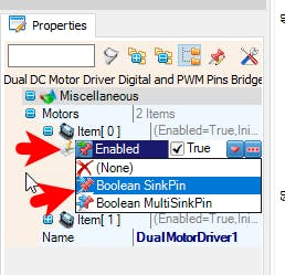
- Select "DualMotorDriver1" and in the properties window select "Motors" > "Item[ 0 ]" > "Enabled" and click on the pin Icon and select "Boolean SinkPin"
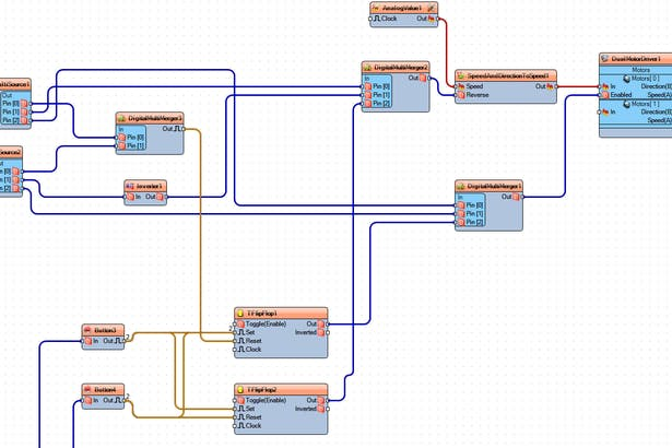

- Connect "DualMotorDriver1" > [Motors.Item[0].Direction] pin [Out] to "Arduino" pin Digital pin [8]
- Connect "DualMotorDriver1" > [Motors.Item[0].Speed] pin [Out] to "Arduino" pin Digital > Analog PWM pin [6]
- Connect "SpeedAndDirectionToSpeed1" pin [Out] to "DualMotorDriver1" > [Motors.Item[0] pin [In]
- Connect "AnalogValue1" pin [Out] to "SpeedAndDirectionToSpeed1" pin [speed]
- Connect "DigitalMultiMerger2" pin [Out] to "SpeedAndDirectionToSpeed1" pin [Reverse]
- Connect "Arduino" digital pin [11] to "Button1" pin [In]
- Connect "Button1" pin [Out] to "MultiSource1" pin [In]
- Connect "Arduino" digital pin [12] to "Button2" pin [In]
- Connect "Button2" pin [Out] to "MultiSource2" pin [In]
- Connect "Arduino" digital pin [9] to "Button3" pin [In]
- Connect "Button3" pin [Out] to "TFlipFlop1" pin [Set] and "TFlipFlop2" pin [Set]
- Connect "Arduino" digital pin [10] to "Button4" pin [In]
- Connect "Button4" pin [Out] to "TFlipFlop1" pin [Set] and "TFlipFlop2" pin [Reset]
- Connect "MultiSource1" pin [0] to "DigitalMultiMerger3" pin [0]
- Connect "MultiSource1" pin [1] to "DigitalMultiMerger2" pin [0]
- Connect "MultiSource1" pin [2] to "DigitalMultiMerger1" pin [0]
- Connect "MultiSource2" pin [Pin[0]] to "DigitalMultiMerger3" pin [1]
- Connect "MultiSource2" pin [1] to "Inverter1" pin [In]
- Connect "MultiSource2" pin [2] to "DigitalMultiMerger1" pin [1]
- Connect "Inverter1" pin [Out] to "DigitalMultiMerger2" pin [1]
- Connect "DigitalMultiMerger1" pin [Out] to "DualMotorDriver1" > [Motors.Item[0] pin [Enabled]
- Connect "DigitalMultiMerger2" pin [Out] to "SpeedAndDirectionToSpeed1" pin [Reverse]
- Connect "DigitalMultiMerger3" pin [Out] to "TFlipFlop1" pin [Reset]
- Connect "TFlipFlop1" pin [Out] to "DigitalMultiMerger1" pin [2]
- Connect "TFlipFlop2" pin [Out] to "DigitalMultiMerger2" pin [2]
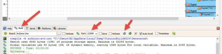
In Visuino, at the bottom click on the "Build" Tab, make sure the correct port is selected, then click on the "Compile/Build and Upload" button.
Step 8: PlayIf you power the Arduino module and press the buttons on the remote control the Linear Actuator will start to move.
Congratulations! You have completed your project with Visuino. Also attached is the Visuino project, that I created for this tutorial, you can download it here and open it in Visuino: https://www.visuino.eu
Schematics, diagrams and documents
Code
Credits
Related products


Leave your feedback...