

Raspberry Pi Home Security System With Hexabitz Modules

Made by Aula_Jazmati / Garden / Home Automation / Kids & Family / Security / IoT
About the project
In this project, we will be combining the power of Raspberry Pi, Hexabitz, and a Pi camera to create a motion detection camera system.
Project info
Difficulty: Moderate
Platforms: Raspberry Pi, STMicroelectronics
Estimated time: 1 hour
License: MIT license (MIT)
Items used in this project
Hardware components

View all
Story
In this project, we will be combining the power of Raspberry Pi, Hexabitz modules, and a Pi camera to create a motion detection camera system. Whenever motion is detected, the camera will be activated and start streaming live video to a local IP address on the internet. This project can be useful for home security purposes or monitoring specific areas remotely.

Have you ever wanted to keep an eye on your home or office while you're away? With this project, you can easily set up a surveillance system that will notify you whenever there is any motion detected in the area.
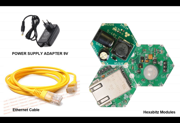
The heart of this project is the Raspberry Pi, a small but powerful computer that can be used for a variety of projects. We will be using it to control the Pi camera and receive the data from Hexabitz modules via Ethernet cable.
The PIR motion sensor is a passive infrared sensor that detects changes in temperature. When a person or an animal moves in front of the sensor, it detects the change in temperature and sends a signal to the Raspberry Pi.
Once the Raspberry Pi receives the signal from the Hexabitz modules, it activates the Pi camera and starts recording video. The video is then streamed to a local IP address on the internet, which can be accessed from any device with an internet connection.
This project is perfect for anyone who wants to keep an eye on their home or office while they're away. With just a few simple components and some basic programming skills, you can set up your own surveillance system in no time!
🏡 UDP Communication:User Datagram Protocol (UDP) refers to a protocol used for communication throughout the internet. It is specifically chosen for time-sensitive applications like gaming, playing videos, or Domain Name System (DNS) lookups.
User Datagram Protocol

User Datagram Protocol
- Used for simple request-response communication when the size of data is less and hence there is lesser concern about flow and error control.
- It is a suitable protocol for multicasting as UDP supports packet switching.
- Normally used for real-time applications which can not tolerate uneven delays between sections of a received message.
Learn more:
https://wiki.python.org/moin/UdpCommunication
https://www.geeksforgeeks.org/differences-between-tcp-and-udp/
🏡 Tools:Temperature, Humidity, Light, Color and Motion Sensor Hub:
H0AR9x is sensor hub module with STM32G0 MCU and a variety of sensors:
- Weather: TI HDC1080DMBT digital temperature and relative humidity sensor.
- Light: Broadcom (Avago) APDS-9950 proximity, ambient light and RGB color sensor.
- Motion: Panasonic EKMC1601111 proximity infrared motion detector (PIR).
Use this module as an indoors weather station, room monitoring node or put on board aerial or ground robotics platform to gather surrounding data. Connect with other Hexabitz modules to log sensor measurements, stream data wirelessly or control external devices based on sensor readings.
1 / 2 • Temperature, Humidity, Light, Color and Motion Sensor Hub

Temperature, Humidity, Light, Color and Motion Sensor Hub
")
Panasonic EKMC1601111 proximity infrared motion detector (PIR)
Hexabitz 10Base-T Ethernet Module (H1DR5):
10Base-T Ethernet module plays a crucial role in enabling devices to communicate over Ethernet networks using the 10Base-T standard. It provides the necessary hardware support for data transmission and reception, ensuring reliable and efficient network connectivity.
Hexabitz 10Base-T Ethernet Module (H1DR5)
")
Hexabitz 10Base-T Ethernet Module (H1DR5)
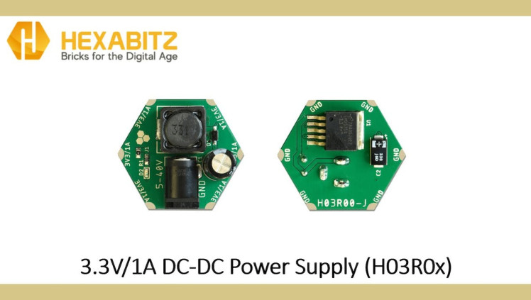
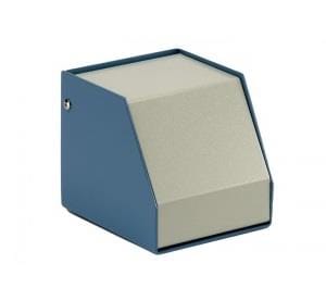
3.3V/1A DC-DC Power Supply (H03R0x):
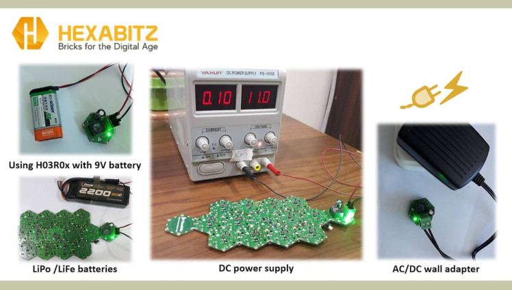
H03R0x is a compact DC-DC buck power supply with a 3.3V/1A DC output and 5-40V DC input. The output voltage is provided through Hexabitz SMD edge-pad connectors (3.3V on top and GND on bottom). The -T module version comes with a 5.08 mm terminal block connector for input voltage, while the -J comes with a DC power jack. Use this module to power all your Hexabitz creations (and other hardware) from a DC source (battery, AC/DC wall adapter, etc.).
1 / 3
")
3.3V/1A DC-DC Power Supply (H03R0x)
STLINK-V3MODS Programmer (H40Rx):
H40Rx is a programmer module which contains STLINK-V3MODS stand-alone debugging and programming mini probe for STM32 micro-controllers (Hexabitz modules and other MCUs). It supports the SWD (Serial Wire Debugging) interface for the communication with any STM32 micro-controller located on an application board. It also provides bridge interfaces to several communication protocols, allowing for instance the programming of the target through boot-loader.
STLINK-V3MODS Programmer (H40Rx)
")
STLINK-V3MODS Programmer (H40Rx)
Raspberry Pi Camera Module 2:
The v2 Camera Module has a Sony IMX219 8-megapixel sensor (compared to the 5-megapixel OmniVision OV5647 sensor of the original camera).
The Camera Module 2 can be used to take high-definition video, as well as stills photographs. It’s easy to use for beginners, but has plenty to offer advanced users if you’re looking to expand your knowledge. You can read all the gory details about IMX219 and the Exmor R back-illuminated sensor architecture on Sony’s website, but suffice to say this is more than just a resolution upgrade: it’s a leap forward in image quality, colour fidelity, and low-light performance. It supports 1080p30, 720p60 and VGA90 video modes, as well as still capture. It attaches via a 15cm ribbon cable to the CSI port on the Raspberry Pi.
The camera works with all models of Raspberry Pi 1, 2, 3 and 4. It can be accessed through the MMAL and V4L APIs, and there are numerous third-party libraries built for it, including the Picamera Python library. See the Getting Started with Picamera resource to learn how to use it.
Raspberry Pi Camera Module 2

Raspberry Pi Camera Module 2
🏡 Step-by-Step Instructions:1. Setting up the Raspberry Pi:
- Install Raspbian OS on your Raspberry Pi.
- Connect the necessary peripherals such as keyboard, mouse, and monitor.
- Ensure that your Raspberry Pi is connected to the internet.
- Enable Camera of Raspberry Pi: Go to Menu-> Preferences -> Raspberry pi configuration -> interfaces -> Enable Camera or Enable Camera Interface in raspi-config by running "sudo raspi-config" in Terminal.
Enable Camera of Raspberry Pi

Enable Camera of Raspberry Pi
- Connect the ribbon cable from the camera module to the CSI port on your Raspberry Pi.
- Set a Static IP Address on Raspberry Pi.
Right click on the network status icon and select the Wireless & Wired Network Settings

Right click on the network status icon and select the Wireless & Wired Network Settings
Select the appropriate interface. If you're configuring a static IP for For Ethernet, choose eth0

Select the appropriate interface. If you're configuring a static IP for For Ethernet, choose eth0
Enter the IP addresses into the relevant fields. Your desired IP address will be in the IPv4 field. Your router's IP and DNS server's IP will be in the fields named after them.
Click Apply, close the window and reboot your Pi. Your Pi will now attempt to use your desired IP address at each boot.
Enter the IP addresses into the relevant fields

Enter the IP addresses into the relevant fields
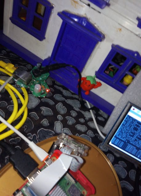
2. Plan the array and assemble the hardware:
We prepare the project components and plan our array design by aligning modules side-by-side. Then we solder the modules together using Hexabitz Fixture.

3.Writing codes with STM32CubeIDE software:
Check out this article for writing code with STM32CubeIDE.
· Fixed topology file: Inter-array communication in Hexabitz is done using a routing table stored in a special header (.h) file. This header file describes the number of modules and how they are connected to each other as well as other important information for the array; hence, it is called a topology header file. Currently, you need to make a topology file manually.
After creating the topology for the two modules and determining their configurations, we add the topology for each module. See this link for help in creating a topology file.
/*
 BitzOS (BOS) V0.2.9 - Copyright (C) 2017-2023 Hexabitz
 All rights reserved

 File Name     : topology.h
 Description   : Array topology definition.

 */

/* Define to prevent recursive inclusion -------------------------------------*/
#ifndef __topology_H
#define __topology_H
#ifdef __cplusplus
 extern "C" {
#endif

/* Includes ------------------------------------------------------------------*/
#include "stm32g0xx_hal.h"

#define __N	2					// Number of array modules

// Array modules
#define _mod1	1<<3
#define _mod2	2<<3

// Topology
static uint16_t array[__N ][7] ={
	{_H0AR9,  _mod2 | P5, 0, 0, 0, 0, 0}, 								 // Module 1
	{_H1DR5,0, 0,0, 0, _mod1 | P1, 0},					    			 // Module 2
};

// Configurations for duplex serial ports
#if ( _module == 1 )
	#define	H0AR9	1
	#define	_P1pol_normal	1
	#define	_P2pol_normal	1
	#define	_P3pol_normal	1
	#define	_P4pol_normal	1
	#define	_P5pol_normal	1
	#define	_P6pol_normal	1
#endif

#if ( _module == 2 )
	#define	H1DR5			1
	#define	_P1pol_normal	1
	#define	_P2pol_normal	1
	#define	_P3pol_normal	1
	#define	_P4pol_normal	1
	#define	_P5pol_reversed	1
	#define	_P6pol_normal	1

#endif


#ifdef __cplusplus
}
#endif
#endif /*__ topology_H */

/************************ (C) COPYRIGHT HEXABITZ *****END OF FILE****/
Then go to project.h as shown in the photo below and UN-comment the header.
project.h file

project.h file
H0AR9x Firmware main.c code:
First, we define our variables:
uint16_t motion;
char data_to_send[10];
Second, inside the while(1) function, we write our code:
void UserTask(void *argument){
// put your code here, to run repeatedly.
while(1){
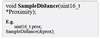
SampleDistance(&motion);
sprintf(data_to_send,"%f", motion);
messageParams[0] = 8; //length
memcpy(&messageParams[1],&data_to_send,8);
SendMessageToModule(2,CODE_H1DR5_Ethernet_Send_Data,9);
Delay_ms(50);
IND_blink(100);
}
}And in the repeated closed loop, we made sure that MCU periodically checks the motion value of the sensor using the API from module factsheet.
Then you can send the data to Ethernet module:

H1DR5 Firmware main.c code:
In this module we adjust the settings for the ethernet:
uint8_t myGateway[4]={192,168,1,100};
uint8_t mySubnet[4]={255,255,255,0};
uint8_t myIP[4]={192,168,1,101};
uint8_t Mac_addres[6]={0x07,0x6,0x2,0x3,0x4,0x5};
Set Local_Mac_addr:
Set_Local_mac_addr(Mac_addres); // Mac_addr ethernetSet_Local_IP:
Set_Local_IP(myIP);Set_SubnetMask:
Set_SubnetMask(mySubnet);Set_Remote_IP:
Set_Remote_IP(myGateway);Set_Local_PORT:
Set_Local_PORT(35);Set_Remote_PORT:
Set_Remote_PORT(34);Set_reseve_mac_and_ip_Remote:
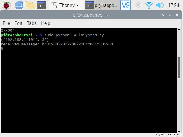
Set_reseve_mac_and_ip_Remote();3. Writing Python Code:
- Install necessary libraries such as picamera using pip.
- Write Python code that sets up camera settings, and handles motion detection events via UDP Communication..
- When motion is detected, capture an image or start recording video using the camera module.
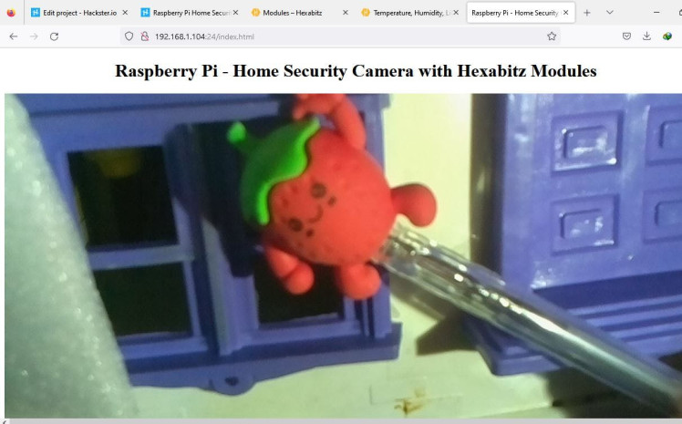
4. Live Streaming:
- Set up a local web server on your Raspberry Pi using any other web framework.
- Create a web page that can display the live video stream from the camera module.
from http import server
PAGE="""
<html>
<head>
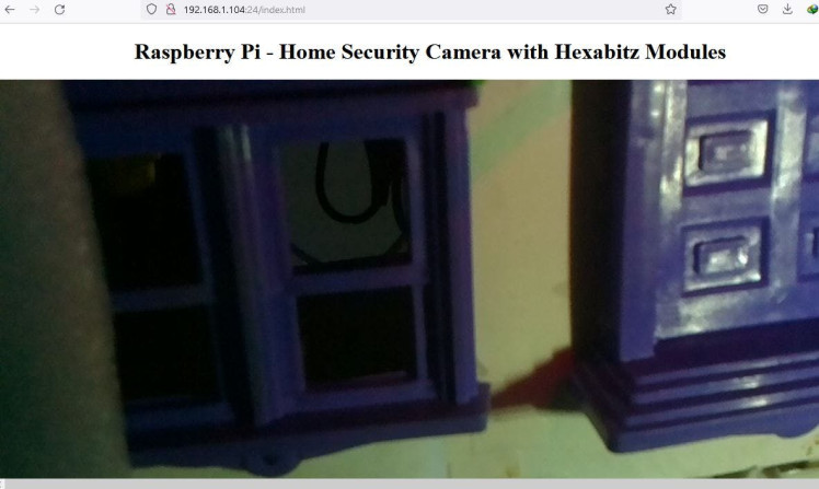
<title>Raspberry Pi Home Security Camera with Hexabitz Modules</title>
</head>
<body>
<center><h1>Raspberry Pi Home Security Camera with Hexabitz Modules </h1></center>
<center><img src="stream.mjpg" width="1280" height="720"></center>
</body>
</html>
"""- Find out your Raspberry Pi IP address: Open terminal and type this command
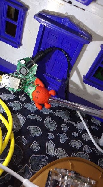
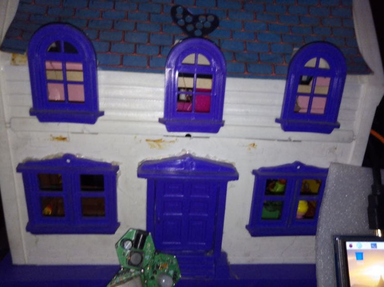
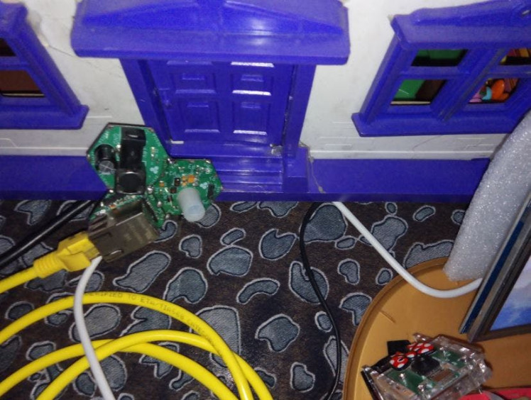
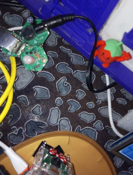
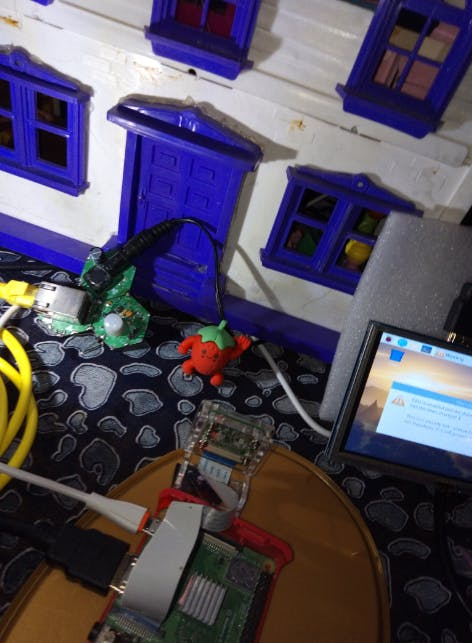
hostname -I5. Testing and Deployment 🎥🏡🔐🦋
1 / 4
1 / 3
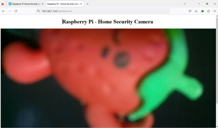
By combining Raspberry Pi, Hexabitz modules, and a Pi camera, we have successfully created a motion detection camera system with live streaming capabilities. This project can be expanded further by adding additional features such as email notifications or integrating it with other smart home devices. Feel free to experiment and customize this project according to your requirements.
Schematics, diagrams and documents
Code
Credits
Related products


Leave your feedback...