


Playing With Ultra-sensitive Magnetometer Rm3100

Made by StanChicago / Environmental Sensing / IoT
About the project
Read RM3100 magnetometer data and send it to IoT site for visualization
Project info
Difficulty: Moderate
Platforms: Arduino, Everything ESP, ThingSpeak
Estimated time: 2 days
License: GNU General Public License, version 3 or later (GPL3+)
Items used in this project
Hardware components


Story
RM3100 sensor board connected to ESP32 controller , measured magnetic field values sent to ThingSpeak IoT for visualization; RM3100 can register magnetic field changes of about 0.2 uT.
Details
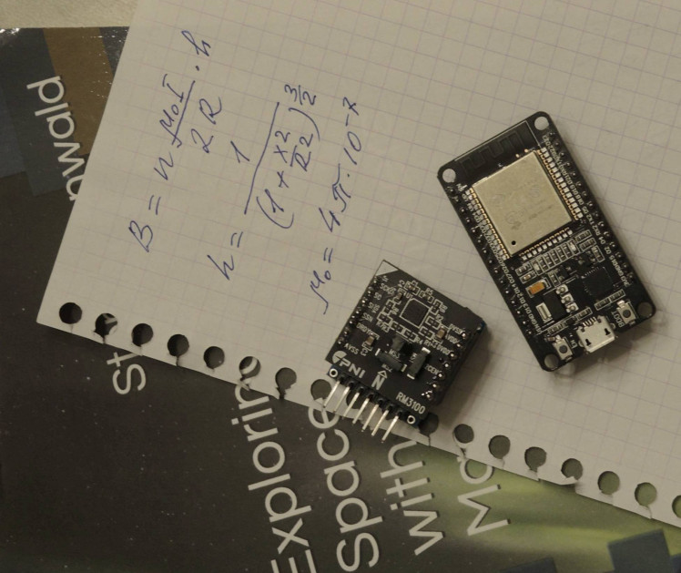
This project was inspired by the book of Sten Odenwald 'Exploring Space Weather with DIY Magnetometers'.
The book presents several simple DIY ways of registering the changes in geomagnetic field.
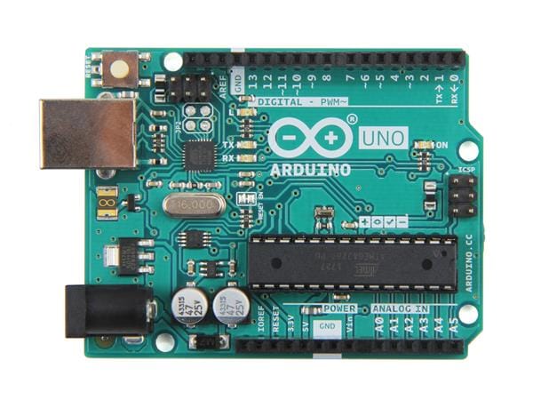
Among them there is a chapter describing how to use a sensitive magnetometer board RM3100 connected to Arduino UNO micro-controller. Magnetometer was developed by PNI Sensor Corporation; there is a detailed guide from PNI for interfacing this sensor with Arduino platform; the guide is available at https://github.com/hnguy169/RM3100-Arduino/tree/main
For the reference, here is RM3100 specification from PNI:
https://www.tri-m.com/products/pni/RM3100-User-Manual.pdf
Arduino-based construction described in the book is very basic; so I decided to try this sensor board myself having in mind to produce somewhat more elaborated design; when working on this small project I had a lot of fun and also learned some new tricks. So I think it might be worth sharing my experience with the community of fellow makers and also to express a gratitude to Sten Odenwald for sharing with us such an inspirational piece of his own knowledge and experience.
So below are the main features of my implementation of Arduino-based magnetometer:
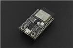
1. ESP32 board as a main controller(MCU). It allows to overcome RAM restrictions of most Arduino boards; it is also capable of connecting to Internet with WiFi.
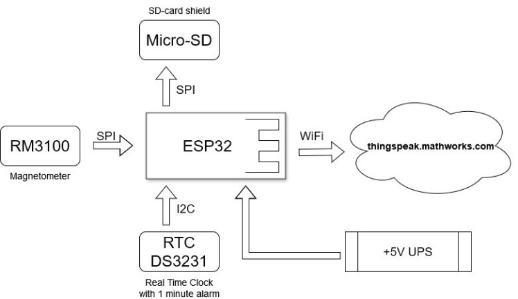
2. Magnetometer RM3100 communicates with MCU through SPI interface
3. SD-card board is attached to MCU (SPI interface as well) and every minute averaged magnetometer reading alone with exact timestamp is stored on micro-SD card in .csv file. Upon every power-on MCU creates automatically a new file on SD with unique name.
SD card can be extracted during the working cycle without stopping the measurements; if SD card is re-inserted, a new file with timestamp is created on the card and data is placed into the new file;
4. There is a simple two-color LED indicator of MCU functioning: permanent red while connecting to WiFi router/modem, blinking red if SD card is missing, blinking green when data processing is normal.
5. MCU reads magnetometer data based on the state of 'data ready' pin of RM3100; Magnetometer "cycle counts" parameter is set to 400. (I found that setting this parameter to 800 does not increase sensitivity but greatly increase the noise level. )
MCU reads 3 components of magnetic field and calculates the total value as

After that it calculates moving average value Bavg in a window of 10 readings;
6. There is a high precision RTC (real time clock) board attached to MCU via I2C interface. RTC uses DS3231 chip with temperature compensation. RTC board provides a timestamp for creating a data file on SD and also for each magnetometer measurement; it also generates an alert (changes the status of designated pin) every 60 seconds; when this alert occurs the current value of Bavg is recorded on SD along with current timestamp.
7. Besides recording data on SD card, the measurements are also sent to the internet to IoT platform ThingSpeak.com.
WiFI connection credentials and ThingSpeak channel write key are stored on SD and can be easily adjusted;
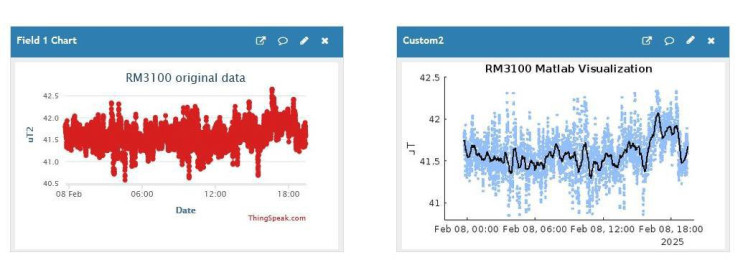
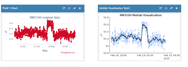
Using this data MCU connects to my local cable modem/router (Comcast) through WiFi; after connection with network is established it sends every minute a http request to api.thingspeak.com to my free account. This account has a public channel where the data is visualized as a time series plot. ThingSpeak.com provides only basic visualization, but it also offers to utilize Matlab Visualization application for more sophisticated processing of incoming data.
So I made a simple template-based program for Matlab app: it implements Savitzky–Golay filtering of incoming data and displays the result as a smooth curve superimposed over the original data points.
Here is an example of ThingSpeak visualization of magnetometer data:
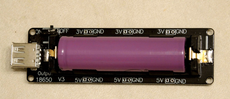
I also decided to insure the stability of power supply for project boards, so I attached a battery shield board with a single 18650 element; this board is connected to wall USB +5V adapter, and all my MCU and add-ons are powered for this 'UPS' unit: in normal mode it keeps 18650 charged and produces +5V power output; in case of external power interruption it still generates output voltage until 18650 battery is depleted; by my experience it can provide nearly 10 hours of standalone power supply.
Here is a diagram of my project assembled:
PARTS AND WIRING
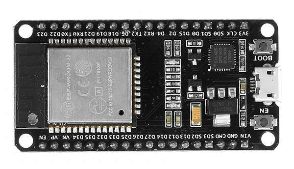
ESP32 board - ESP-WROOM-32 DEVKIT V1
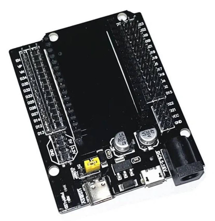
For convenience MCU mounted on expansion board:
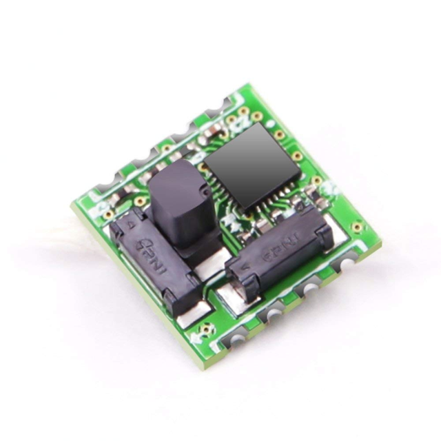
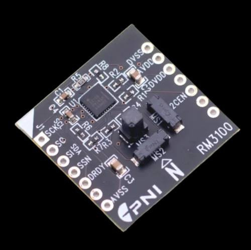
I used two versions of RM3100 boards that are available:
'Board 1':
'Board 2'
 I made a simple 'adapter' for RM3100 breakout:
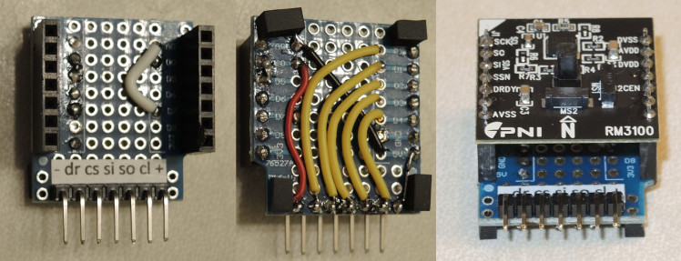
RM3100 to ESP32 wiring:
Per diagram from PNI RM3100 Arduino Quick Guide https://github.com/BrownSpaceEngineering/RM3100-Magnetometer/blob/main/RM3100%20Arduino%20Quick%20Guide.pdf:
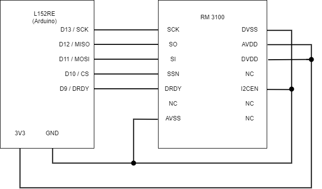
RM3100 CS - ESP32 Pin D5
RM3100 DRDY - ESP32 Pin D34
RM3100 SI - ESP32 Pin D23
RM3100 SO - ESP32 Pin D19
RM3100 SCK - ESP32 Pin D18
RM3100 AVSS, DVSS, I2CEN - ESP32 GND
RM3100 AVDD, DVDD - ESP32 +3.3V
SD breakout board to ESP32 wiring:
Shares SPI bus with RM3100, different CS pin
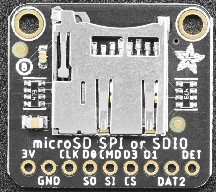
SD card CS - ESP32 Pin D26
SD card SI - ESP32 Pin D23
SD card SO - ESP32 Pin D19
SD card SCK - ESP32 Pin D18
SD 3V - ESP32 +5V*
*by some reason when powered from 3.3v works less stable, fails to initialize quite often
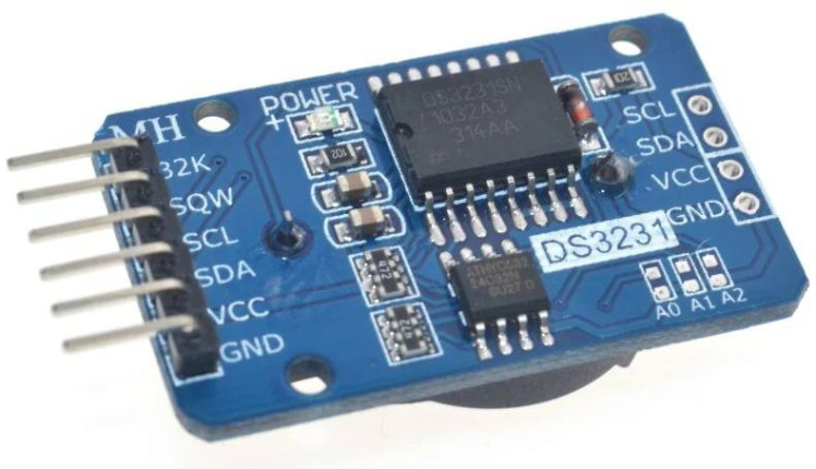
RTC SCL - ESP32 Pin D22
RTC SDA - ESP Pin D21
RTC SQW (alarm pin) - ESP32 Pin D4
Powered from ESP32 +5V
"UPS" board:
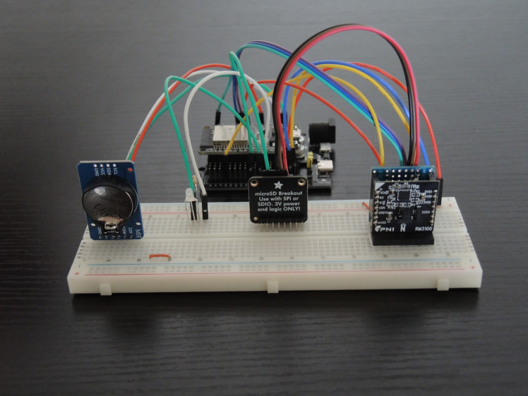
The project assembly:
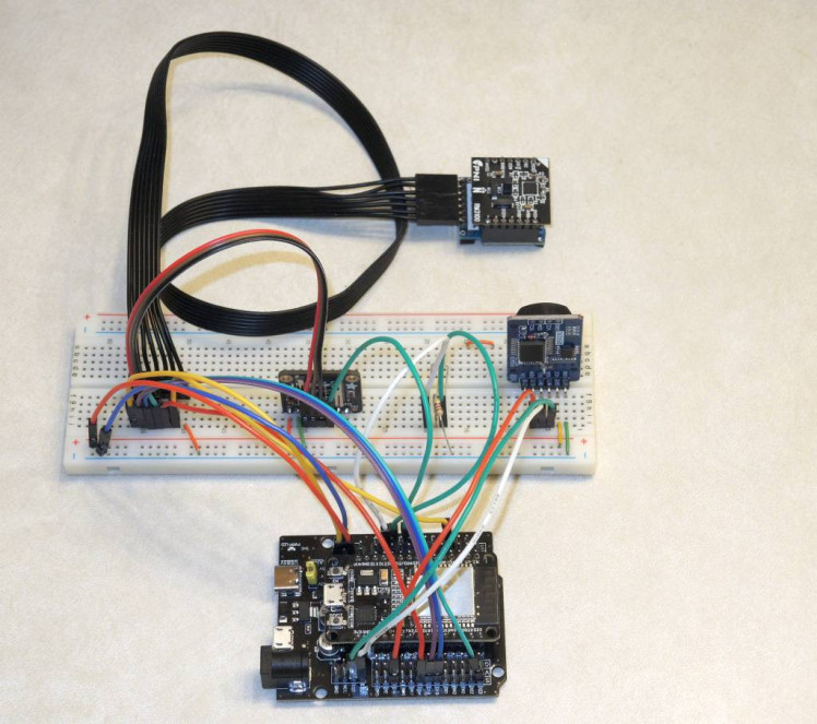
For experiments with magnetometer orientation and easy placement I also made a flexible connecting cable from flat silicon 26AWG ribbon:
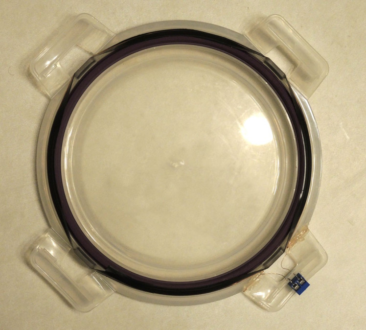
I also conducted some experiments for verifying magnetometer sensitivity and estimating its noise level. For this I made a primitive 'Helmholtz coil' using a plastic lid from kitchen container similar to this one:

My coil has 10 turns of AWG35 copper wire and a diameter of 17.2 cm:
PNI document claims that RM3100 noise level at Cycle Count 200 is about 15 nT. This is definitely over-optimistic statement; by my experiments even at Cycle Count 400 the noise level is at best 100 nT ; sometime noise level spontaneously increases to 300 nT and returns to lower level after power cycling:
Here is the research from UK Liverpool University dedicated to estimating RM3100 characteristics.
It shows that without very serious shielding the noise level of RM3100 is in the range of ~160-200 nT with SD value of 0.03uT
When shielding with multi-layered container and 'copper room' is provided, noise decreases to ~20nT which is close to official specification data (15nT). If we need to detect geomagnetic events, no shielding can be used; so this means that in regular, common industrial environment without shielding the sensor can reliable detect field deviations starting from 150-200 nT. This is consistent with my results: I observed reliable readings change when external field of ~200nT was applied by Helmholtz coil; but field's intensity change below 100nT hardly can be detected reliably.
This limitation can be probably overcame by locating a sensor at some environment essentially free from industrial magnetic fields, like some rural area, far from any industrial and electronic activity;
Measurements
Two types of measurements were conducted:
1. short-term recordings to determine sensor normal noise level and sensitivity. Normally, 3-5 hours.
2. Long term data acquisitions attempting to register geomagnetic events.
For the first type of experiments sketch ESP32_RM3100_NOISE_AND_SENSITIVITY was used (see attached files).
I also used simplified setup - just ESP32 board connected to sensor via SPI, no SD card and no RTC board:
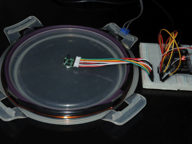
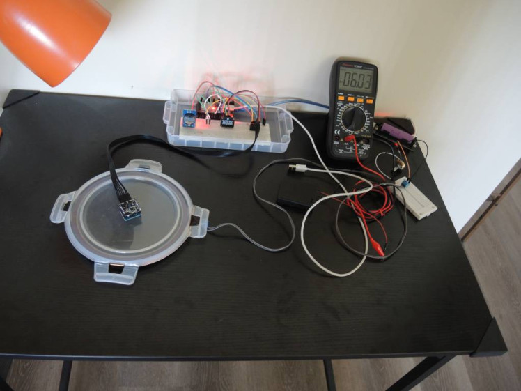
Sensor was placed in the center of coil; for testing a sensitivity I energized the coil form 3AAA batteries and maintained a current of 6 mA. Here is the working moment of measurements. Here I use a full project setup with SD-card and attached RTC board; but for this type of measurements neither of them is used.
Magnetic field on the central axis of a flat circular coil is calculated as (see here f.e.)
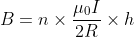
where n - number of coil turns, I - coil current, A, R - coil radius,m,
μ0 = 4π × 10−7 is the vacuum permeability, h is an adjustment for the distance 'x' between flat coil center and measurement point:
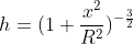
So with R=8.6 cm, I=6 mA, n=10, x=2 cm we have h=0.92 and B=403nT ~400nT
Sensor was polled every 15 seconds, readings were used to calculate
B value was submitted to RunningAverage procedure in Arduino sketch with moving window of 10 readings. Current average value of B was sent every 15 seconds to ThingSpeak IoT server. Besides standard ThinkSpeak line chart I also added a Matlab Visulaization chart that combines scatter plot of raw data and a plot of Savitzky–Golay filtered curve with a characteristic factor of 160. Matlab program code is attached below (see 'matlab_code.txt')
Results of noise and sensitivity measurements
Here are plots of 'Board 2' sensor data for 12 hours; in the middle we can see data increase when the coil was activated for 80 minutes.
Standard Deviation of first 6 hours (prior to coil activation) is equal to 0.094;
Visually I would estimate the noise level (peak to peak) as ~0.1 - 0.2 uT. Coil activation results in readings increase by ~0.4 uT which matches calculated value (above).
Here is smoothed data in more details: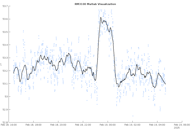 Similar data for the another sensor board ('Board 1'):
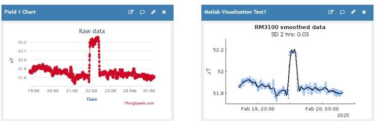
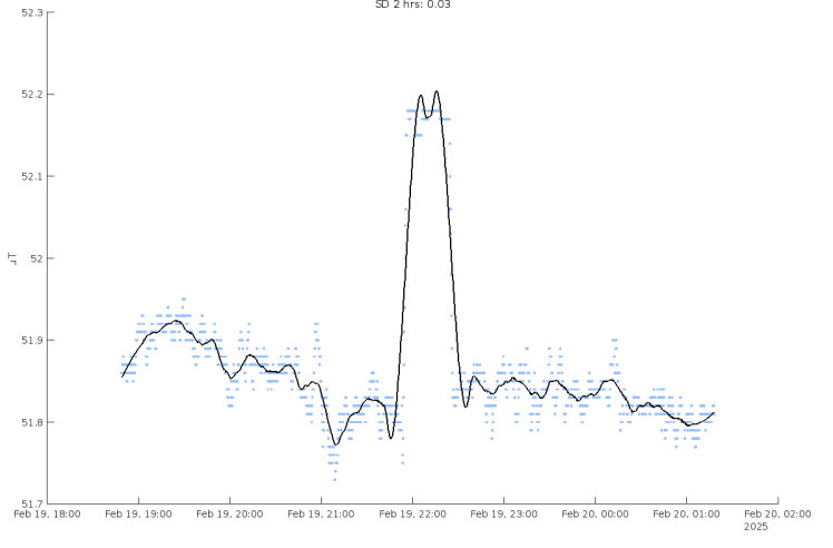 Noise level for this sensor board is definitely lower, probably in the range on 50-100nT peak-to-peak; accordingly, SD value for initial interval of 2 hrs is 3 times smaller then for the other sensor board.
I also made some recordings when coil current was only 3 mA which theoretically produced a field of 200nT: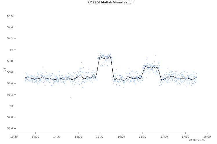 This is data obtained from sensor 'Board 2'.
Sensor boards instability
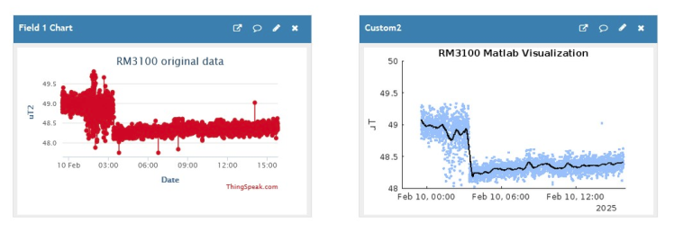
I observed in several cases a spontaneous noise change and value drifting of sensor readings.
Here is an example of increase noise level; it decreased after power cycling (sensor 'Board 2'):
Another case when sensor reading were drifting linearly immediately after power on; when power was turned off and then re-connected the drifting stopped (sensor 'Board 1'):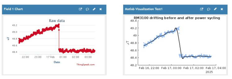 As of now I don't have any explanation for such instability; I can suggest this is individual features of my sensor boards; maybe selecting/testing multiple sensor boards could reveal more stable items.
Long Term Measurements
To obtain long-term magnetometer readings I used both sensors simultaneously, both at the same location, each connected to it's own MCU, both MCU were running the identical code, just sending data to different ThingSpeak channels. I also modified Matlab program to show plots from both sensors in the same window, for comparison. The idea was to observe a real difference in sensor boards sensitivity and detect simultaneous reading changes, distinguishing them from individual boards outliers and noise.
The result can is available at my public channel https://thingspeak.mathworks.com/channels/2799462
The top chart shows data from sensor 'Board 1' and the bottom one - from 'Board 2'.
Data plot of free account on ThingSpeak can hold up to 8000 data points; so I am planning to run both sensors for a while and these plots theoretically would show 5 days of observations.
Conclusion
From my observations, RM3100 sensor boards without special shielding have a noise level of 50-200 nT; individual sensor boards have different noise level, different readings when placed in identical conditions; sensors also can demonstrate some instability, like, spontaneous change of noise level and drifting of readings. Power cycling also affects sensors instability.
As I understand, RM3100 sensors initially were not designed for measuring subtle field changes of geomagnetic events; with certain precautions and having in mind possible data instability these boards probably could be used for 'Space weather' observations, especially in case of events of a high intensity, but, by my opinion, mostly for demonstration and hardly for exact measurements.
Project code
There is a problem with attaching source file on this site, so for your convenience here is ESP32/Arduino code used for sensitivity and noise testing:
/************************************************************
* Konstantin Dorohov, February 2025
* WHAT: ESP32+WIFI+WWW
* No alarm, sending data every 60000ms to selected channel
* averaging permanently 50 window
* */
#include <SPI.h>
#include <WiFi.h>
#include "RunningAverage.h"
String s_ssid="xxxxx";
String s_wifi_pwd="xxxxx";
String s_api_key="xxxxxxx";
char server[] = "api.thingspeak.com";
int connection_timeout=50;
int v_avg_count(50);
long t0,t60;

//pin definitions
#define PIN_CS 5
#define PIN_DRDY 34


//internal register values without the R/W bit
#define RM3100_REVID_REG 0x36 // Hexadecimal address for the Revid internal register
#define RM3100_POLL_REG 0x00 // Hexadecimal address for the Poll internal register
#define RM3100_CMM_REG 0x01 // Hexadecimal address for the Continuous Measurement Mode internal register
#define RM3100_STATUS_REG 0x34 // Hexadecimal address for the Status internal register
#define RM3100_CCX1_REG 0x04 // Hexadecimal address for the Cycle Count X1 internal register
#define RM3100_CCX0_REG 0x05 // Hexadecimal address for the Cycle Count X0 internal register
#define RM3100_TMRC_REG 0x0B // Hexadecimal address for Sets Continuous Measurement Mode Data Rate

//options
#define initialCC 400 // Set the cycle count

RunningAverage myRA(v_avg_count);
float gain;
double uT, uT_avg, uT_avg_prev, uT_avg_delta;
uint8_t x2, x1, x0, v_y2, v_y1, v_y0, z2, z1, z0;
long x,y,z;
uint8_t revid;
uint16_t cycleCount;


void connectWiFi(){
    int timeout_counter = 0;
    WiFi.mode(WIFI_STA); //Optional
    WiFi.begin(s_ssid, s_wifi_pwd);
    while (WiFi.status() != WL_CONNECTED){
        Serial.print(".");
        delay(200);
        timeout_counter++;
        if(timeout_counter >= connection_timeout){
        Serial.println("Restarting");
        ESP.restart();
        }
    }
    Serial.println("");
    Serial.print("Local ESP32 IP: ");
    Serial.println(WiFi.localIP());
    }

void httpRequest(double fieldData) {
  WiFiClient client;
  if (!client.connect(server, 80)){
      Serial.println("Connection failed");
      client.stop();
      return;
    }
   String data = "field1=" + String(fieldData);
   client.println("POST /update HTTP/1.1");
   client.println("Host: api.thingspeak.com");
   client.println("Connection: close");
   client.println("User-Agent: ESP32WiFi/1.1");
   client.println("X-THINGSPEAKAPIKEY: "+s_api_key);
   client.println("Content-Type: application/x-www-form-urlencoded");
   client.print("Content-Length: ");
   client.print(data.length());
   client.print("nn");
   client.print(data);
   delay(250);
   client.stop();
}

void setup() {
  pinMode(PIN_CS, OUTPUT);
  pinMode(PIN_DRDY, INPUT);
  uT_avg=0;
  myRA.clear();
  digitalWrite(PIN_CS, HIGH);
  SPI.begin(); // Initiate the SPI library
//  SPI.beginTransaction(SPISettings(1000000, MSBFIRST, SPI_MODE0));
  Serial.begin(115200);
  delay(100);
 s_ssid.trim();
 s_wifi_pwd.trim();
 connectWiFi();

  revid = readReg(RM3100_REVID_REG);

  Serial.print("REVID ID = 0x"); //REVID ID should be 0x22
  Serial.println(revid, HEX);

  changeCycleCount(initialCC); //change the cycle count; default = 200 (lower cycle count = higher data rates but lower resolution)

  cycleCount = readReg(RM3100_CCX1_REG);
  cycleCount = (cycleCount << 8) | readReg(RM3100_CCX0_REG);

  Serial.print("Cycle Counts = "); //display cycle count
  Serial.println(cycleCount);

  gain = (0.3671 * (float)cycleCount) + 1.5; //linear equation to calculate the gain from cycle count

    // Enable transmission to take continuous measurement with Alarm functions off
    writeReg(RM3100_CMM_REG, 0x79);
 //  writeReg(RM3100_TMRC_REG, 0x9C); //0.6Hz 1.72s
  t0=millis();
  t60=millis();
   }

void loop() {
if (millis()-t0>15000) {
   if (digitalRead(PIN_DRDY)) {
    x = 0; y = 0; z = 0;
    //read measurements
    digitalWrite(PIN_CS, LOW);
    delay(100);
    SPI.transfer(0xA4); //sends 'read' command to register 4
    x2 = SPI.transfer(0); //following 9 bytes of data
    x1 = SPI.transfer(0);
    x0 = SPI.transfer(0);
    v_y2 = SPI.transfer(0);
    v_y1 = SPI.transfer(0);
    v_y0 = SPI.transfer(0);
    z2 = SPI.transfer(0);
    z1 = SPI.transfer(0);
    z0 = SPI.transfer(0);
    digitalWrite(PIN_CS, HIGH);
    //taking care of possible negative value
    if (x2 & 0x80) x = 0xFF;
    if (v_y2 & 0x80) y = 0xFF;
    if (z2 & 0x80) z = 0xFF;
    //  //format results into single 32 bit signed value
    x = (x * 256 * 256 * 256) | (int32_t)(x2) * 256 * 256 | (uint16_t)(x1) * 256 | x0;
    y = (y * 256 * 256 * 256) | (int32_t)(v_y2) * 256 * 256 | (uint16_t)(v_y1) * 256 | v_y0;
    z = (z * 256 * 256 * 256) | (int32_t)(z2) * 256 * 256 | (uint16_t)(z1) * 256 | z0;
    uT = sqrt(pow(((float)(x) / gain), 2) + pow(((float)(y) / gain), 2) + pow(((float)(z) / gain), 2));
    myRA.addValue(uT);
   }
   t0=millis();
   if (millis()-t60>60000) {
    uT_avg = myRA.getAverage();
       Serial.print(myRA.getAverage(),2);
      Serial.print(" ");
      Serial.println(myRA.getStandardDeviation(),2);
      if (WiFi.status() != WL_CONNECTED) connectWiFi();
      httpRequest(uT_avg);
      t60=millis();
   }
  }
}

//addr is the 7 bit value of the register's address (without the R/W bit)
uint8_t readReg(uint8_t addr){
  uint8_t data = 0;
  digitalWrite(PIN_CS, LOW);
  delay(100);
  SPI.transfer(addr | 0x80); //OR with 0x80 to make first bit(read/write bit) high for read
  data = SPI.transfer(0);
  digitalWrite(PIN_CS, HIGH);
  return data;
}

//addr is the 7 bit (No r/w bit) value of the internal register's address, data is 8 bit data being written
void writeReg(uint8_t addr, uint8_t data){
  digitalWrite(PIN_CS, LOW);
  delay(100);
  SPI.transfer(addr & 0x7F); //AND with 0x7F to make first bit(read/write bit) low for write
  SPI.transfer(data);
  digitalWrite(PIN_CS, HIGH);
}

//newCC is the new cycle count value (16 bits) to change the data acquisition
void changeCycleCount(uint16_t newCC){
  uint8_t CCMSB = (newCC & 0xFF00) >> 8; //get the most significant byte
  uint8_t CCLSB = newCC & 0xFF; //get the least significant byte

  digitalWrite(PIN_CS, LOW);
  delay(100);
  SPI.transfer(RM3100_CCX1_REG & 0x7F); //AND with 0x7F to make first bit(read/write bit) low for write
  SPI.transfer(CCMSB);  //write new cycle count to ccx1
  SPI.transfer(CCLSB);  //write new cycle count to ccx0
  SPI.transfer(CCMSB);  //write new cycle count to ccy1
  SPI.transfer(CCLSB);  //write new cycle count to ccy0
  SPI.transfer(CCMSB);  //write new cycle count to ccz1
  SPI.transfer(CCLSB);  //write new cycle count to ccz0
  digitalWrite(PIN_CS, HIGH);
}
Schematics, diagrams and documents
Credits
Related products


Leave your feedback...