

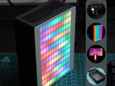
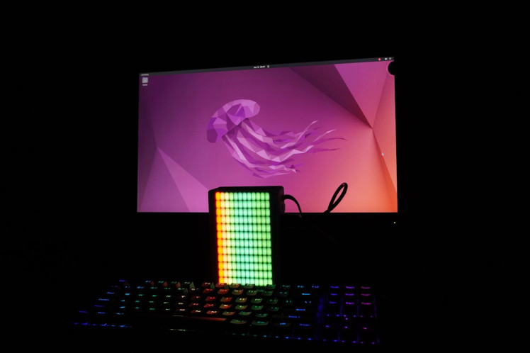
Pixelpanda | A 3d Printed Rgb Matrix Pc Build

Made by mukesh-sankhla / 3D Printing / Displays / Games & Gaming / Lights / Retro Tech
About the project
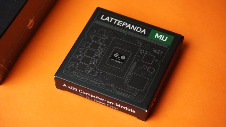
A 3D printed custom PC based on new LattePanda MU.
Items used in this project
Hardware components

Software apps and online services
Story
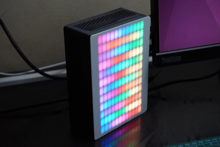
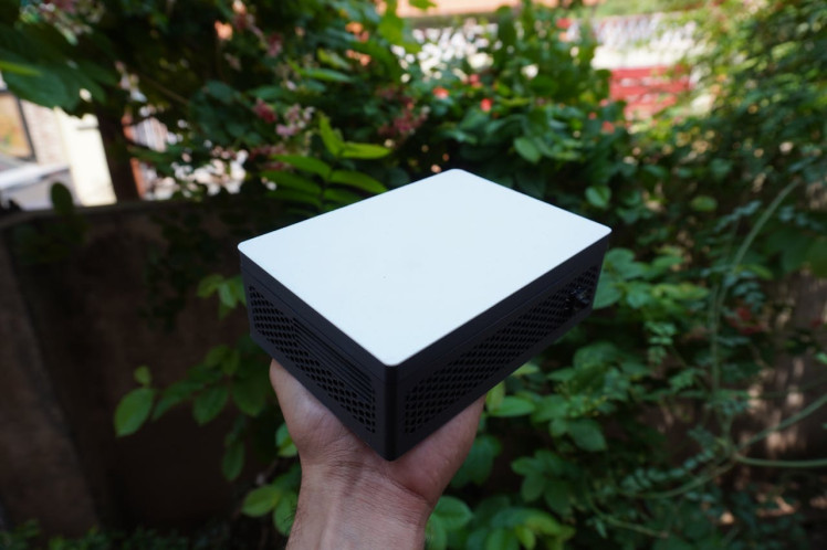

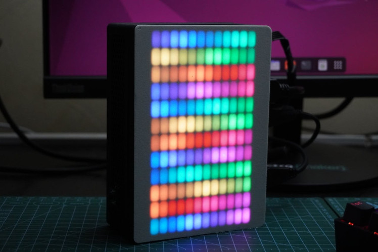
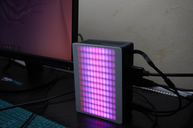
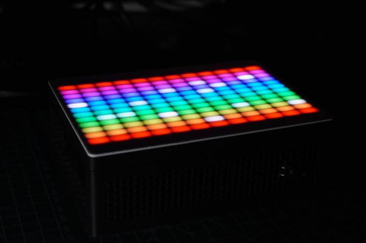
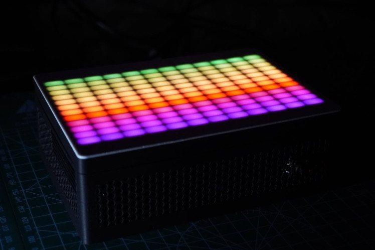
PixelPanda is an exciting project that combines the powerful LattePanda MU computer with a custom 3D printed case and a Pixel LED matrix for colorful RGB animations. It's perfect for tech enthusiasts, makers, and anyone who loves creative tech projects.
Key Features:
- Custom 3D Printed Case: Specially designed to fit the LattePanda MU.
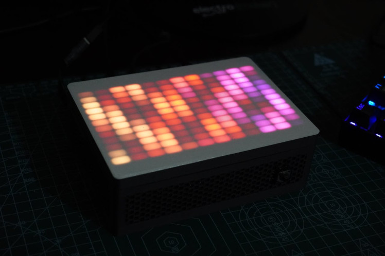
- Dynamic RGB Animations: Displays vibrant LED animations that you can customize.
- User-Friendly Software: Customize and control the LED animations with ease.
- Animation Options: Choose from pre-programmed animations or create your own.
- Powerful and Compact: The LattePanda MU serves as the powerful heart of the build.
- Versatile Uses: Can function as a mini PC, server, NAS, and more.
Sponsored By NextPCB
This project is successfully completed because of the help and support from NextPCB -Reliable Multilayer PCB Manufacturer. Through conversations with their engineers, it was clear that they put in their best effort to manufacture durable and well-performing PCBs. If you prefer quality but also want affordability, don't miss NextPCB.
Free PCB Prototypes for New Customers up to $30: https://www.nextpcb.com
Additionally, their HQDFM (Design for Manufacturability) services help improve your designs. Personally, I find HQDFM the best and quickest way to do a self-check before production, eliminating the repetitive wait for DFM reports from manufacturers.
DFM free online PCB Gerber viewer: https://www.nextpcb.com/free-online-gerber-viewer.html
Supplies

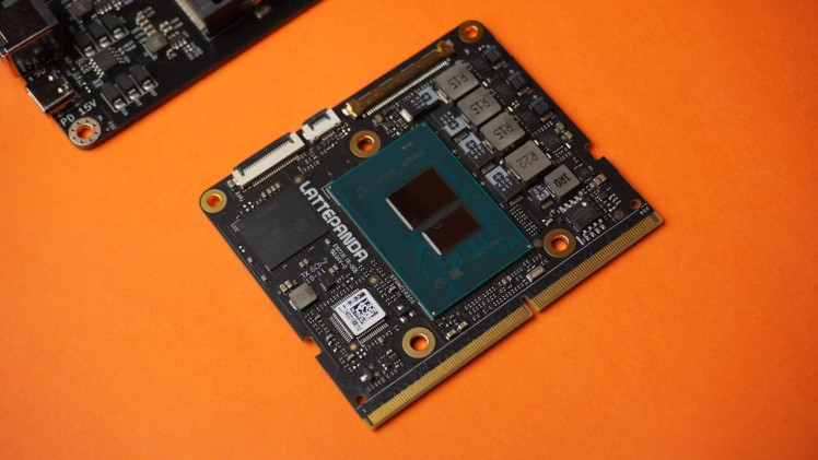
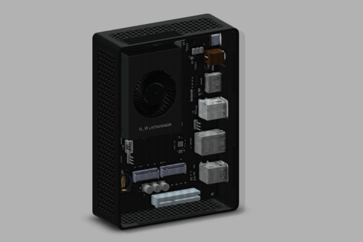
About LattePanda Mu
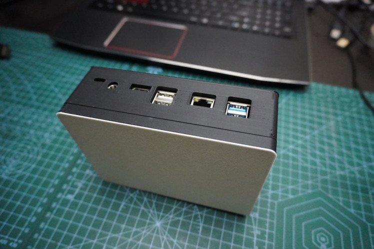
LattePanda Mu is a micro x86 compute module featuring Intel N100 quad-core processor, 8GB LPDDR5 memory and 64GB storage. LattePanda Mu exposes extensive pins, including 3 HDMI/DisplayPort, 8 USB 2.0, up to 4 USB 3.2, up to 9 PCIe 3.0 lanes. These flexible ports and open-source carrier board files enable users to effortlessly design custom carrier boards to meet their unique requirements.
Small but Powerful
LattePanda Mu x86 compute module features Intel N100 quad-core processor with 3.4GHz turbo frequency, offering ample performance and multitasking capabilities for the majority of applications.
Equipped with an Intel Processor N100, LattePanda Mu compute module offers a multi-core score of 3115 and a single-core score of 1217 on Geekbench 6, outperforming the Raspberry Pi 5, Intel Celeron N5105, and Atom x5-Z8350. Its CPU performance doubles the Raspberry Pi 5.
Card-Sized
Despite its small size of 69.6mm x 60mm, The pocket size of the LattePanda Mu N100 computer-on-module allows for integration into space-constrained devices, delivering powerful computation without occupying much space.
Flexibility in Performance and Energy
The processor's TDP can be adjusted from 6W to 35W, providing flexibility in power usage and heat output. The 6W setting enables efficient operation with minimal heat and silent passive cooling, while the 35W setting offers robust performance but requires active cooling.
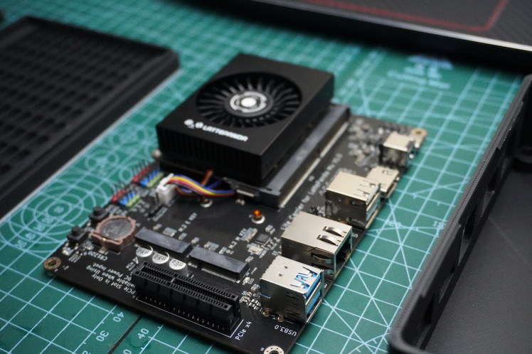
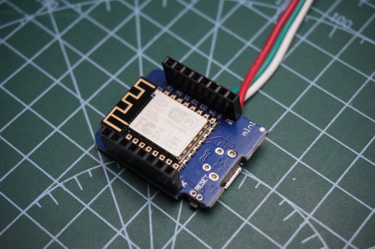
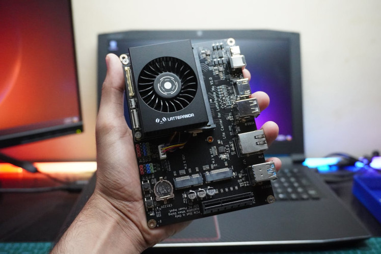
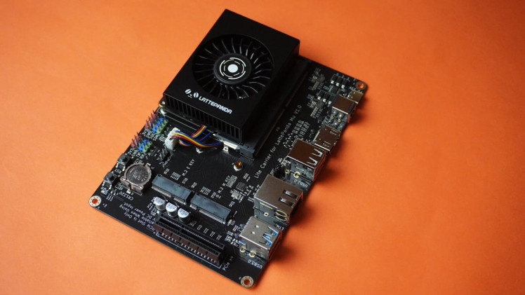
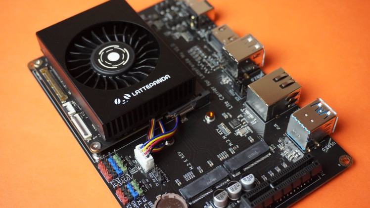
Step 1: LattePanda Assembly
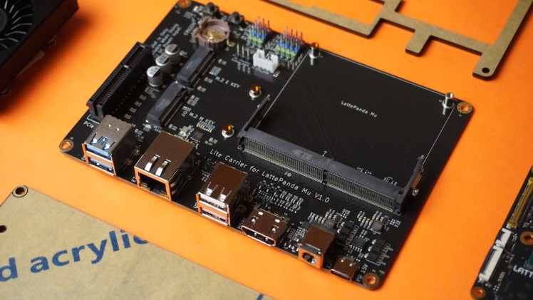
- Attach the LattePanda MU to the carrier board.
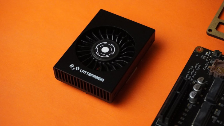
- Remove the screws from the aluminum cooling fan.
- Remove the sticker from the heating pad, align the cooling fan with the LattePanda MU, and screw them together.
- Align the LattePanda MU with the slot on the lite carrier board and insert it.
- Connect the fan cable to the fan slot on the carrier board.
- Insert the RTC coin cell battery that came with the board.
And that's how simple it is.
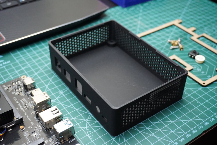
Step 2: Case Design
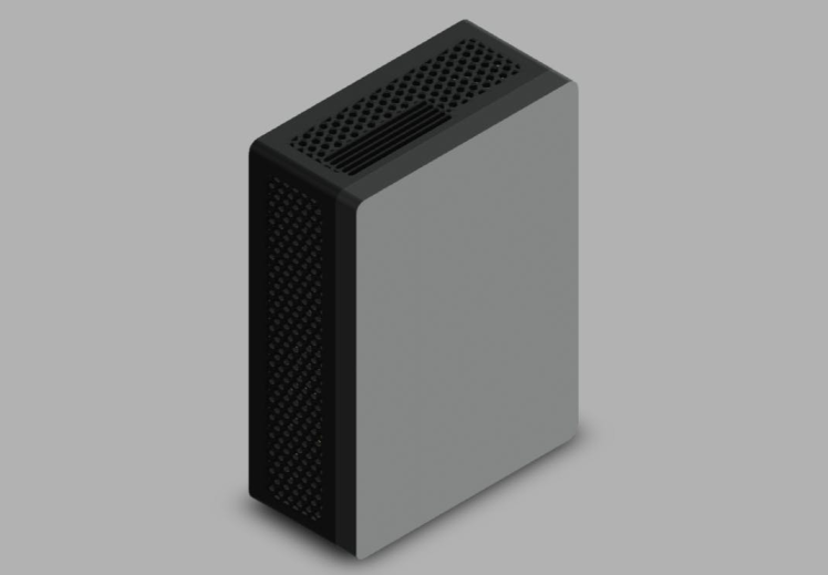
I used Fusion 360 to design the case for this project.
- You can directly 3D print using the provided STL files, or open the Fusion 360 files to modify them as needed.
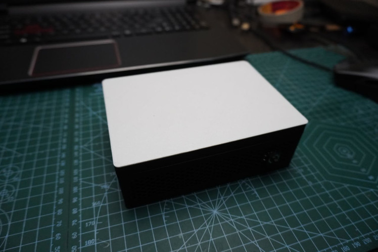
- I have designed two top covers for the case: one with an LED matrix and another with a simple cover.
STL Files:
Fusion 360 Files:
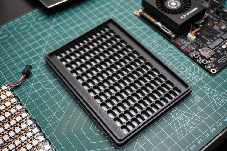
Step 3: 3D Printing
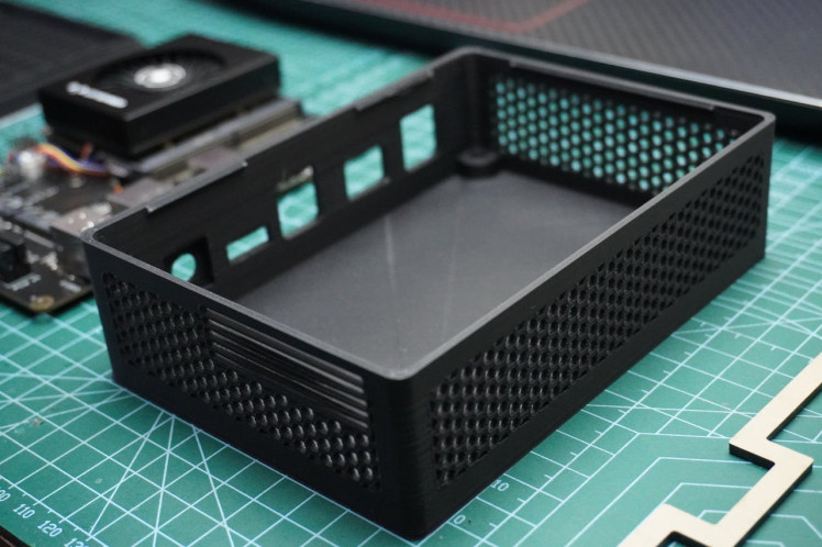
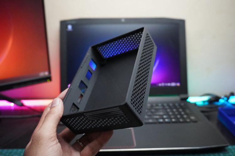
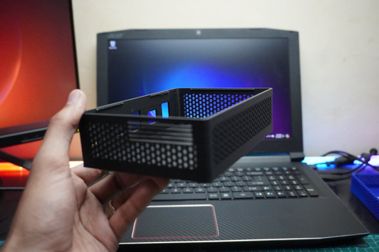
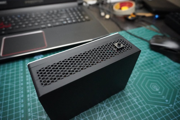
- I 3D printed the housing in matte black PLA.
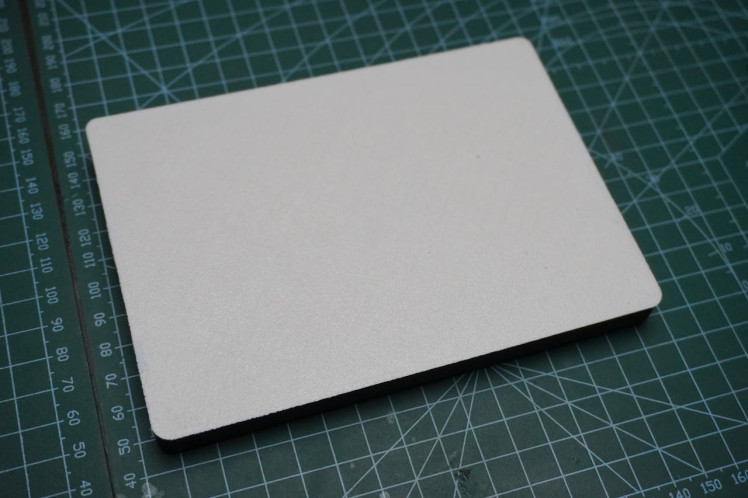
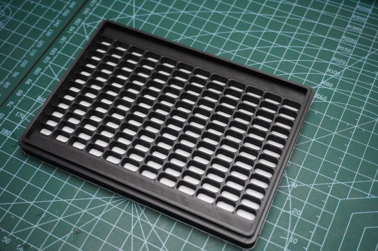
- For the matrix cover, I started with white PLA for the diffuser and then switched to matte black once the printer reached the grid section.
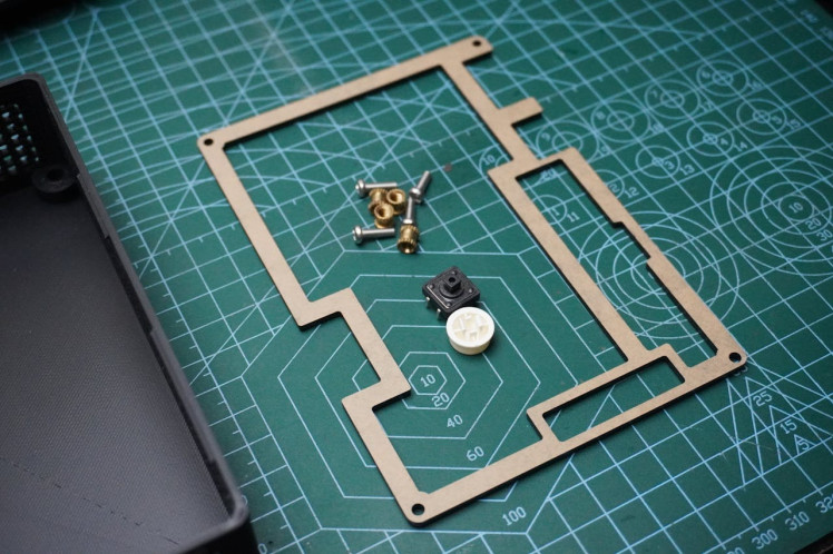
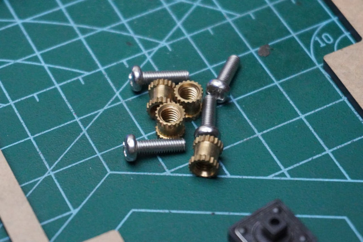
Step 4: Metal Inserts
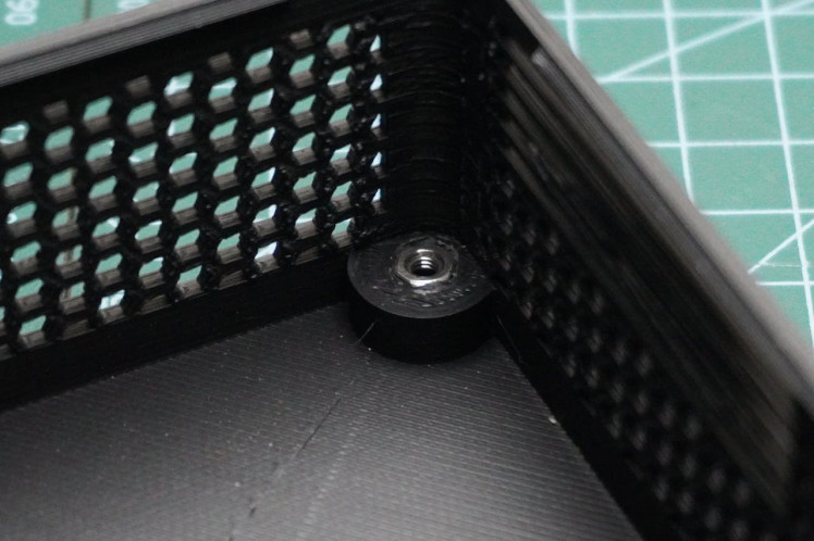
- Now, fuse the metal inserts into the housing. Use M3 metal inserts and a soldering gun to insert them into their respective holes.
- If you don't have M3 inserts, you can use the small metal nuts that came with the carrier board, as I did.
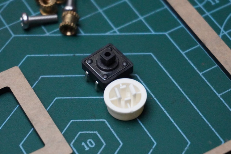
Step 5: Extending Power Button
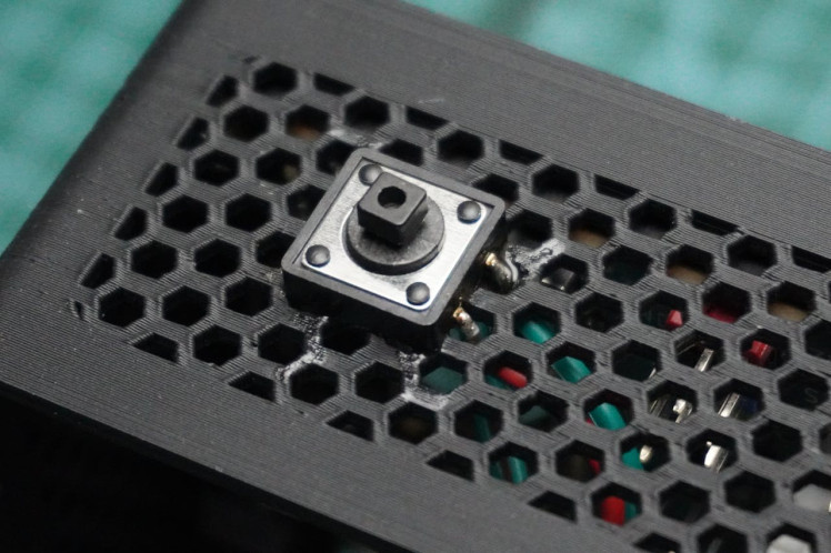
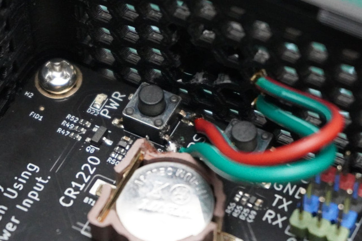
- Extend the power button of the carrier board by soldering a push button.
- Take care during soldering to avoid damaging the carrier board, as it could render it unusable.
- Before soldering, secure the push button in place with glue, then proceed with soldering.
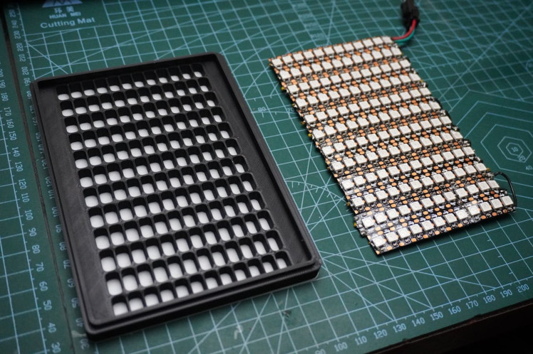
Step 6: LED Matrix
For the LED matrix, we have two options:
1. PCB Matrix Fabrication:
- I have designed a PCB that you can get fabricated. It provides a hassle-free option for direct use without additional effort.
- Gerber Zip File
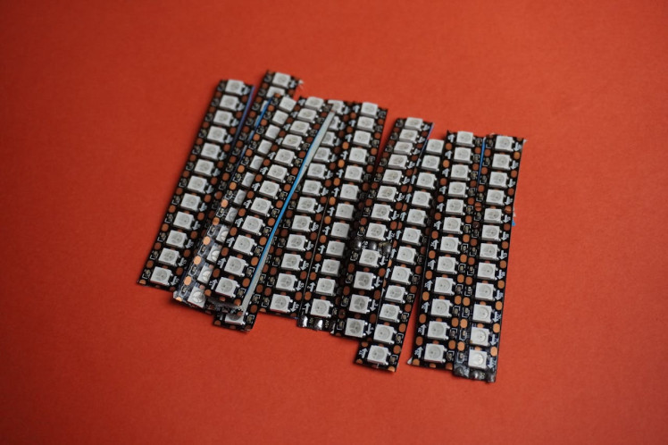
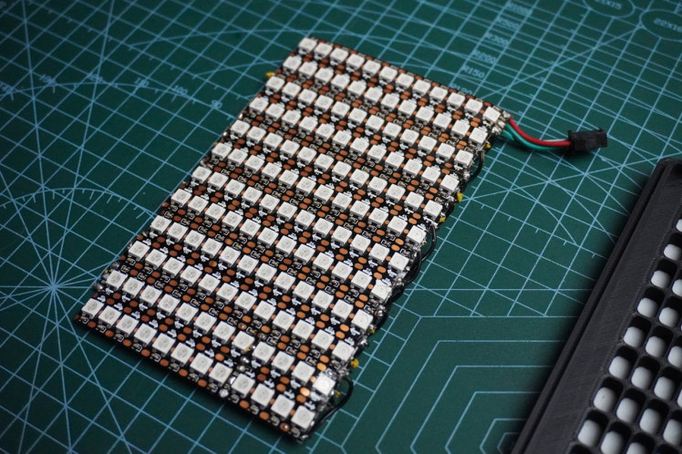
2. Prototype Matrix:
- Alternatively, I created a prototype using WS2812B 144 LED strips. I cut them into sections of 12 LEDs each and assembled them into a matrix by carefully soldering them onto a cardboard base.
- The prototype method requires more effort to ensure everything is done correctly and securely.
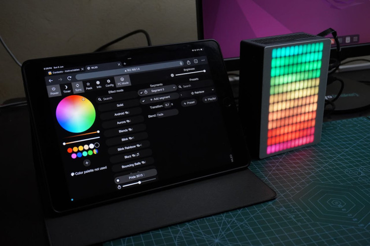
Step 7: Software Setup
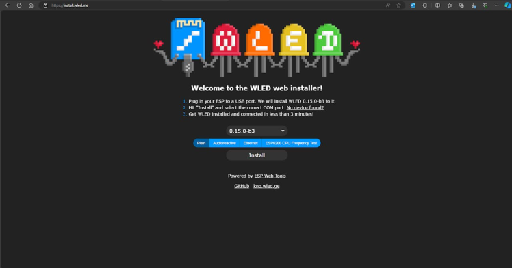
- Connect the Wemos to your PC.
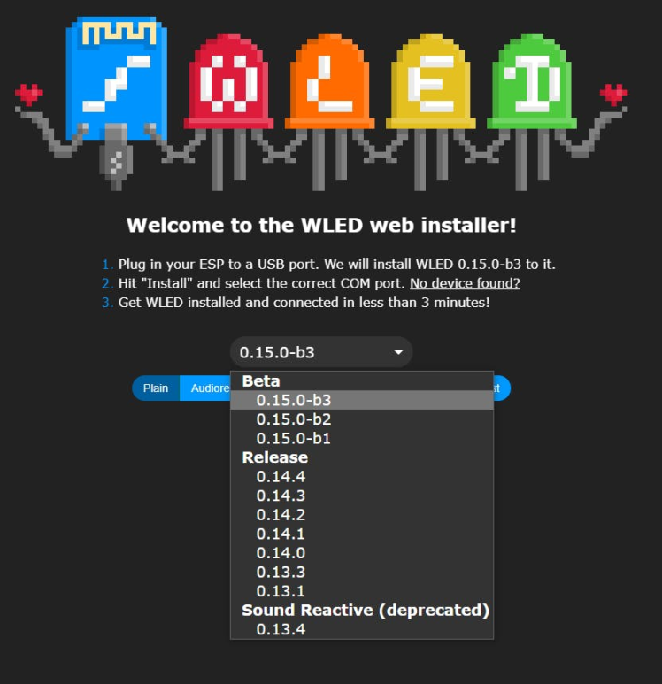
- Visit install.wled.me
- Choose the software version and click "Install."
- Select the correct COM port and click "Install" again.
The installation process will take some time. Once installed, we can proceed with the next steps.
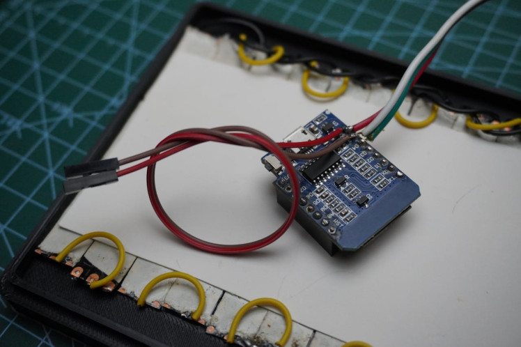
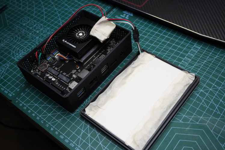
Step 8: Assembling LED Matrix
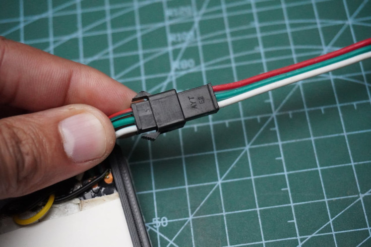
- Now, follow the circuit diagram to connect the LED matrix.
- Use the connectors provided with the LED strip.
- After connecting, test the matrix by powering it on to ensure everything is functioning correctly.
- This step verifies that the LEDs light up as expected and confirms the proper assembly of your LED matrix.
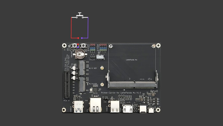
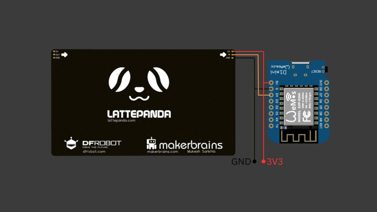
Step 9: Circuit Connection
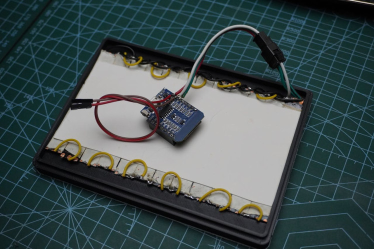
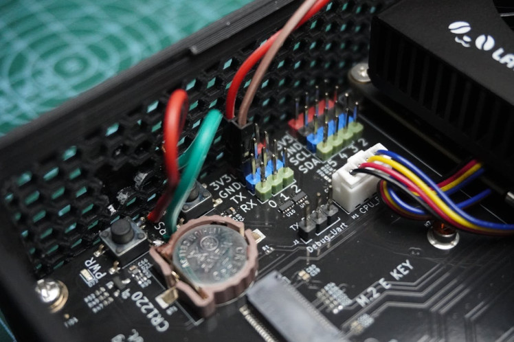
To power the Wemos from the Latte Panda Carrier Board for the LED matrix, follow these circuit connections:
- GND to GND: Connect the ground (GND) from the Wemos board to the ground (GND) on the Latte Panda Carrier Board.
- VCC to 3V3: Connect the power (VCC) from the Wemos board to the 3V3 output on the Latte Panda Carrier Board.
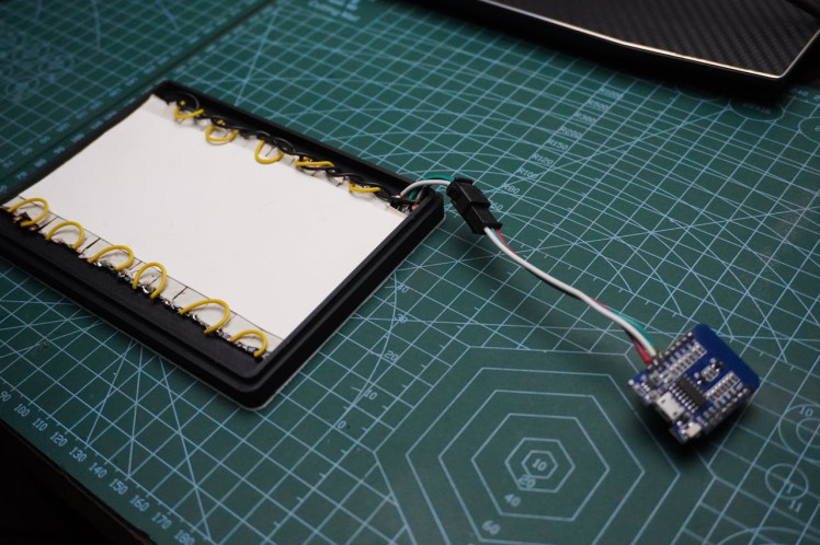
Step 10: Final Assembly
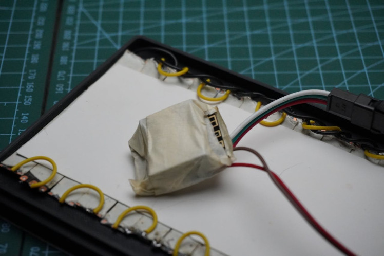
For the final assembly, follow these steps:
- Use masking tape to cover the Wemos board and the LED matrix. This protects them from any accidental contact or damage during assembly.
- Place the cover over the housing and snap it into place securely. Ensure all edges align properly for a snug fit.
- That's it! Your project is now ready to use. Enjoy your completed build!
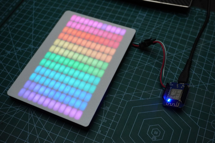
Step 11: Conclusion
You can control the matrix animations using a web app. Check out WLED videos on YouTube or its documentation to customize your animations. Additionally, you can create your own patterns and animations without relying on WLED.
That concludes this project. We hope you enjoyed it! If you did, let us know in the comments.
See you next time with a new project! :)
Schematics, diagrams and documents
CAD, enclosures and custom parts
Code
Credits
mukesh-sankhla
Tech Educator | Content Creator | Developer | Maker - Simplifying technology through hands-on learning. Creating high-quality tutorials, projects, and insights on electronics, IoT, robotics, CAD, 3D printing, and software development at Empowering students, professionals, and makers with practical, accessible, and inspiring content.
Related products


Leave your feedback...