Ping Pong Ball Led Display
About the project
These are the files an advanced maker could use to make a Ping Pong display. Custom PCBs, large 3D prints, and laser cut parts are used to simplify the design and construction significantly.
Project info
Difficulty: Expert
Platforms: Adafruit, Arduino, NeoPixel
Estimated time: 1 day
License: Creative Commons Attribution-NonCommercial CC BY-NC version 4.0 or later (CC BY-NC 4+)
Items used in this project
Hardware components
View all
Hand tools and fabrication machines
Story
These are the files I used to make a ping-pong ball display! This is for somewhat advanced makers and assumes some knowledge to put everything together as well as access to tools. It attempts to simplify other designs out there for similar displays by using large, 3d printed parts to hold the diffusers, Custom PCBs to get the spacing right, and a laser cut back plane for ease of assembly.
Things you will need:
* 20 PCBs - I got mine from JLCPCB 30 boards for $9.30* 128 5050 SMD LEDs that use the standard data format. I used SK6812's because I wanted true white. I bought 1000 of them for $80 on eBay - meaning I used about $10.00 worth for this project. I would suggest buying some extra. * 128 38mm ping (or beer) pong balls. I got plastic so they wouldn't be as flammable as real ping pong balls. Read reviews - if everyone is complaining that they don't bounce right they're perfect for this! (eBay, $15)* 40 M3x4 hex screws (~$5)* Wire* Arduino Uno (or µController of choice)* RTC Module if necessary - I had an old Adafruit D1307 kicking around - $8* 5V 10A power supply (Alitove, Amazon, $20)* I used about 3Kg of filament - ~$60 * 36"x24" Acrylic sheet - ~$10Total is ~$80 hardware and $85 materials for roughly $165
PCBs
General idea should be straight-forward from the photos. Assemble the PCBs (it might make sense to pay JLCPCB to do it for you), install them, wire them up!Some build tips:* Test each strip of LEDs before installing it to the board* The ground pin of the LEDs is the most difficult to solder - if it's bad you'll see garbage data after the LED with a bad ground connection* You can cut the PCBs along the lines to make shorter ones for the shorter diagonals - I used a band saw but a coping saw works too* The power is wired in 5 groups of four strips. This is to be mindful of too much current in an single wire* The wires are doubled up in some (many) holes* Install the PCBs to the backplane before wiring
Diffuser Panel
* Print at whatever settings - Rough is fine.* Insert all of the balls before cutting them - that way they hold pressure* Each ball has a seam - best to keep it turned out of the way* Cut a hole in the bottom of each ball with a sharp hobby knife* Once they're cut they will dent easily - be careful with them
Frame
I printed the frame in four pieces, mirror two of them. I don't love it - I think replacing with wood would look a lot nicer. Be mindful of warping on the corners.
Electronics
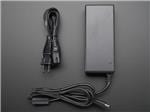
I have a bunch of Unos sitting around so I just used what I had on hand - an ESP32 or something would be super nice for this!I also have an old RTC for the time, again, a better µcontroller would eliminate that need.The DC power supply comes with a barrel-jack-screw-terminal thing that you can use. I made a small PCB that is a partial shield that holds the RTC and distributes the power to the LEDs. It puts the two barrel jacks right next to each other for maximum confusion. The code I've uploaded is super barebones and not very good. It displays the time. It's more or less commented. I will upload better code if I ever write it, but I would rather someone remix this with good code I use VScode + PIO to upload but I think it will work with Arduino Studio.
Problems
Let me know what questions/concerns/necessary information I might have missed. I will help where I can.


