

PAROL6 - Desktop robotic arm

Made by petar-crnjak
About the project
PAROL6 is a high-performance 3D-printed desktop robotic arm. Control software, GUI, and robots STL files are open-source
Project info
Difficulty: Expert
Estimated time: 1 hour
License: GNU General Public License, version 3 or later (GPL3+)
Items used in this project
Hardware components

Story
Full video assembly guide: Link
Github repo with PAROL6 Files and building instructions: Link
Github repo with PAROL commander GUI: Link
Documentation: Link
Join Discord!
Join forum: https://discourse.source-robotics.com
Follow us on Instagram,Youtube, or Twitter!
Official website: https://source-robotics.com
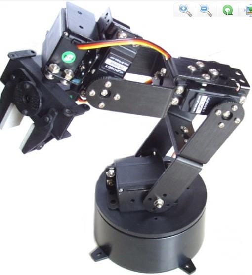
Intro to the robotic armRobot arm repetabilityRobot arm 1kg payloadProblemI first saw a need for robots such as this in my high school days where 30 students were working on one robot. At colleges, it was nothing better. I did some research and that was the situation in most colleges. My first attempt to change that and make it one robot per student was with Faze4. That project was financed by the college but was not a big hit because of its large size, imprecision, and lack of easy-to-use intuitive software. The second time I saw the need for a robot such as PAROL6 was when working as an RnD engineer on electric vehicles. Building a prototype is one thing but building a production is another much harder thing. I saw many ways robots such as PAROL6 could help companies that need to go from RnD to small production, or at least try to accelerate their RnD processes. Tasks such as adding thru-hole components, placing PCBs to test jigs, handling PCB, gluing, inserting brass bushings, and many more could be in some part automated with robots such as PAROL6.Solution
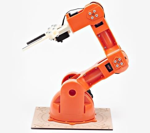
SolutionWith now a large amount of problems that I saw in education and industry I decided to try to tackle them with PAROL6. Just the idea of this kind of robot is nothing new and there are many robotic arm businesses that try to fill this gap but they either fail in terms of price, usability, or lack of support / being open. PAROL6 aims to be a low-price solution, be usable, and be as open source as possible.
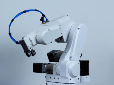
PAROL6 is a desktop robotic arm. Its reach is 400mm and has 6 axes of freedom. Its capabilities are on par with industrial robots in terms of repeatability, speed, and usability. It is equipped with stepper motors and precision planetary reducers/belt drives. Its mechanical parts can be 3D printed on any desktop 3D printer and its full weight is only 5.5 kilograms! In terms of connectivity, it has pneumatic tubes running through the robot and the ability to connect a force-sensitive gripper that is being developed.
The design is minimalistic and because of that can be easily modified. Stepper drivers can be upgraded to a closed loop for almost all axes without any major design changes. For that purpose closed loop stepper drivers running FOC have been developed.
PAROL6 design approachPAROL6 hardware and software design was driven in large part by Faze4 and CM6. From faze 4 mechanical design and from CM6 software and control approach. Advantages of building these robots before this one was the community and contributions to the projects from the people. People build unity simulators, ros control implementation, custom controllers, and modified STEP files... The goal is, like previous robots, to make as much open source as it can. Some of the guidelines that guided the design:
- PAROL6 was built with a specific purpose in mind; Small automation like picking PCBs and placing them in test jigs, adding thru-hole components to PCBs... Another goal was for it to be used in an education setting where one PAROL6 can be used by one student, not 10 students per 1 robot.
- It needs to have a robust simulator and GUI for easy offline programming. The ability to test your programs without a real robot is time-saving and is being done in most professional and industry-standard robots.
- Previous robots of mine used plastic gearboxes and that is a big mistake. They are way too unreliable and bend too much. PAROL6 uses precision planetary gearboxes with 10-15 arcmin backlash (harmonic gearboxes usually have around 5 arcmins). By using quality gearboxes robot has much better repeatability and precision and can make smooth trajectories,
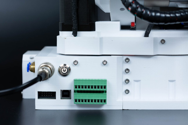
- Robots need good connectivity to interact with the users and the world. PAROL6 has 2 isolated Inputs and 2 isolated outputs for controlling grippers, relays, pneumatics, or connection to PLC-s. It also has a CAN bus for connecting grippers or external devices. To communicate with a PC it uses USB.
- PAROL6 was built with grippers in mind and has routed pneumatic tubes and wires for grippers to its Forearm region.
- A big part of PAROL6 is its software that was again built around Tkinter as GUI and Petar Corke's Python robotic toolbox. That combination has proven to be effective in CM6 and was refined here, Because of that it has a lot of features that no other open-source robotic arm has.
- PAROL6 was designed to be easy to build by using large 3D printed parts and an intuitive design. Also, I believe many DIY robotic arm projects suffer from bad building instructions that lock out some potential users, so PAROL6 has detailed step-by-step building instructions.
GUI / control software is written in Python and the main components are:
- Tkinter for a graphical interface
- CustomTkinter for modern interface design in Tkinter
- Robotic toolbox for Python for kinematics, trajectories...
- multiprocessing library
The control software can be split into 3 processes that run in parallel and share an array of multi-process variables. The main process is then split into 3 threads: Debug, Main/Sender thread and Receive thread. All data sent and received by the control software is saved in multi-process arrays. The main process has its main task is sending data thru serial every 10-20ms. data is sent even if no command is given by the GUI or trajectory planner. That command is called dummy command and it serves as the heartbeat of the robot. If the heartbeat is not received after a specific time robot goes into error mode. The whole package size is: from the robot 60 bytes to the robot 52 bytes. This allows very fast loop times and is simple to maintain. The main task executes all trajectory planning, control logic, and GUI command handling... It is the most important task and is responsible for the operation of the robot. When developing new firmware it could be used as a separate segment of code independent of the other processes.
Receive task runs in the same main loop and is responsible to handle all incoming data. If the robot sends the correct data format with the same start bytes and end bytes, data can be checked with CRC and if it passes, saved to the multi-process variables that GUI, simulator, or main task can use.
The simulator is its own process that runs in real-time. Having a simulator and visual aid when operating a robotic arm is crucial and I am sad that not a lot of other projects try to implement something similar. It should not be a feature reserved for expensive proprietary robots and solutions!
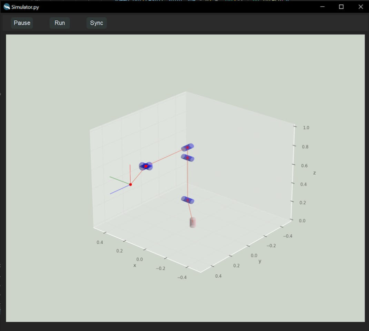
The simulator is a simple skeleton of the robot with an end effector represented as a coordinate frame. It uses matplotlib.
Driver board softwareThe driver board software is in charge of controlling the stepper motors and other peripherals like I/O, CAN bus, ESTOP... After it receives the package from GUI and confirms that it is good by checking CRC, start and end bytes, and package length it unpacks the package. After the package is unpacked robot responds to it with its own package.
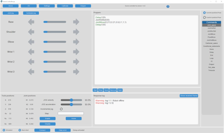
User interface (GUI)GUI was inspired by industrial robot control programs. It was simplified as much as possible to be usable by students but also has all the necessary features that are included in professional software solutions. It can be divided into a few sections. On the left side, we have motor jog and cart jog menus. Under them, we can see the robot's current position. In the middle, we have a programming window and underneath him a response log window. On the right side, we have a commands window for a quick selection of commands for programming.
1 / 2
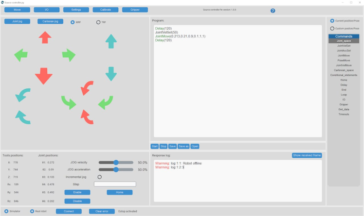
The programming window is used to write programs that will run on your robot. It includes functions like:
- Joint level control
- Cartesian level control
- Speed and acceleration settings
- Delays
- Loops
- I/O control
- Gripper control
The Whole GUI was designed in Tkinter and uses a custom Tkinter module for modern design. It can run on Linux, Windows, and MAC machines.
Mechanical design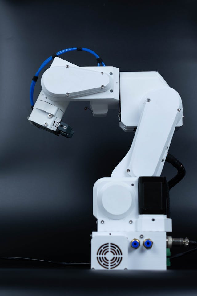
Robot specifications:
- Payload: 1 Kg
- Weight: 5.5 Kg
- Reach: 400 mm with the standard gripper
- Degrees of freedom: 6 rotating joints
- Material: 3D printed PETG plastic
- Power consumption: 40W
- Repeatability:
- Rotation range:
- 1 – 250 deg
- 2 – 141 deg
- 3 – 180 deg
- 4 – 212 deg
- 5 – 180 deg
- 6 - ∞
- Motors: Steppers
- Gearboxes: precision planetary and bets
- Position sensing: Limit switches for open loop version, magnetic encoders for closed-loop version
- Drivers: Open-loop stepper drivers for open loop version, magnetic encoders for closed-loop version
The whole robot should be printed in PETG material since motors and gearboxes can get quite hot.
The placement of the motors was done to minimize the weight the robot joints need to carry and to reduce the inertia of the robot when accelerating.
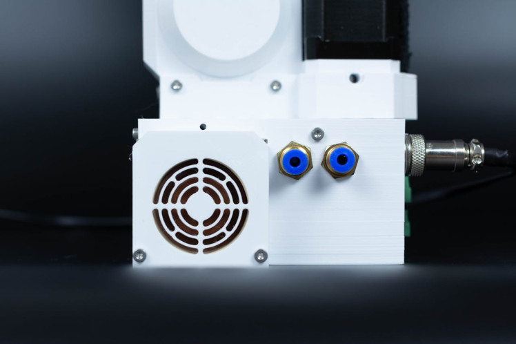
Pneumatic tubes are run thru the robot. They have twofold purpose firstly they allow the connection of pneumatic grippers and vacuum grippers to the robot. Second, since the wires also run thru the robot the tubes act as a solid guide and support for the wires not to twist too much or get tangled.
1 / 2
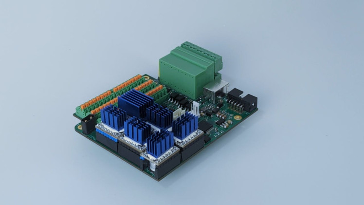
The driver board's main purpose is to execute commands from PC sent to the robot. It is a 6-layer PCB designed to fit the base of the robot. In the future connection to the PC will not be needed since there is room to fit a raspberry pi compute module inside the base of the robot.
Its main components are:
- 6 x silent stepper drivers
- STM32F4 microcontroller
- CAN interface
- Phoenix connectors to connect motors and limit switches
- Isolated I/O
- JTAG programming interface
- FLASH memory for offline operation ( will be able to store programs and execute them without a PC)
- Connectors for Noctua fan and On/Off button
- ESTOP connector
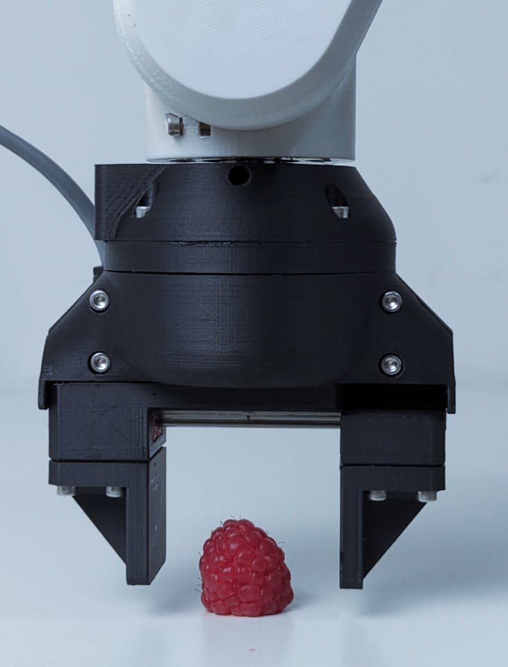
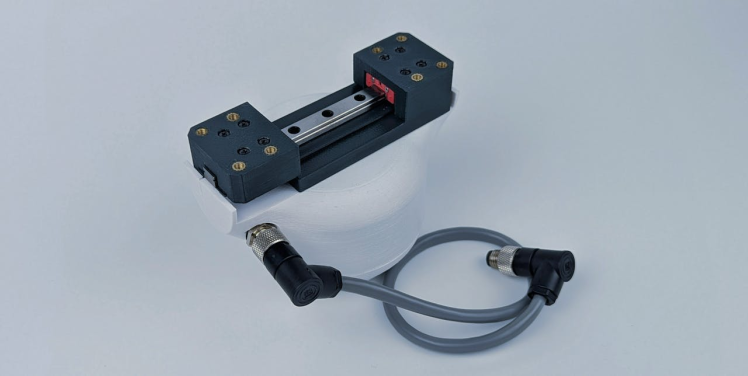
This here will be a small intro to the gripper since it is still a work in progress. It is also in itself really complex project that will be its own project I hope. Same as a PAROL6, a compliant gripper fills the gap in the market. There is, unlike PAROL6 NO open-source compliant force-sensitive gripper that you can build. There are at least dozens of decent robotic arm projects you can build and no decent gripper that is close to the industry level.
1 / 2
CAD, enclosures and custom parts
Code
Credits
petar-crnjak
Our is Bridging the gap between robotic education, research, and industry with accessible and open-source solutions.
Related products


Leave your feedback...