
Motorized Potentiometer
About the project
Control an analog potentiometer with code!
Project info
Difficulty: Moderate
Estimated time: 6 hours
License: GNU General Public License, version 3 or later (GPL3+)
Items used in this project
Hardware components
Story
*See videos below for all details about the build process, issues I encountered, etc.
The Idea
Basically, I wanted the ability to control a potentiometer using a microcontroller. There are a couple options out there to accomplish this.
- Digital Potentiometer ICs. The problem here is that I want to have a physical knob that the user can turn, in addition to digital control.
- Motorized potentiometers off-the-shelf. They do exist, but I can only find them in stock in 1 value, which isn't very useful.
I decided I need to come up with my own solution - connect a standard potentiometer to a motor and spin it. But again, there are considerations.
First, what's the best way to control the potentiometer's position? You may first think of a servo, and that could work, but again, it doesn't do what I want. When a servo is powered, it is always trying to hold a position, which means the user wouldn't be able to turn the knob against the wishes of the servo.
Of course, you could wire up a switching circuit to disable the servo after it reaches it's goal. But then you have another problem. How does the microcontroller know where the potentiometer is now that someone turned it? Servos don't give feedback about their position by default.
So with all this in mind, I landed on a design - connect 2 potentiometers to a DC motor. One can be used for the analog circuit, and the other can be used as a voltage divider, providing positional feedback. Then you stick in PID control, and voila, you can send the pots to whatever position you want, and you can read the position set by manual control.
Mechanical Design
I decided to use gears to make the connections between the motor and both potentiometers. I used 42 tooth gears for each pot and 10 tooth for the motor. So roughly 4 revolutions of the motor equals 1 revolution of a potentiometer. As it turns out, the cheap motor I had chosen struggles to turn this load (more about that later), but the 4:1 ratio turned out to be the best I could get it with the parts I had available.
Now, you may be thinking - wait a minute, there's no way to attach a gear to potentiometer. Well, that's correct. So I had to improvise. I removed the bottom casing from the potentiometer and glued in 10 tooth gear, which happened to almost perfectly fit in the plastic on the bottom of the pot. Then I cut a hole in the metal casing to fit this gear through and put it back on. This gear isn't for turning stuff, though. It barely pokes through the base. Rather, it provides a 2mm hole to add a shaft, which is the standard size for the other plastic gears you'll actually use to get stuff spinning.
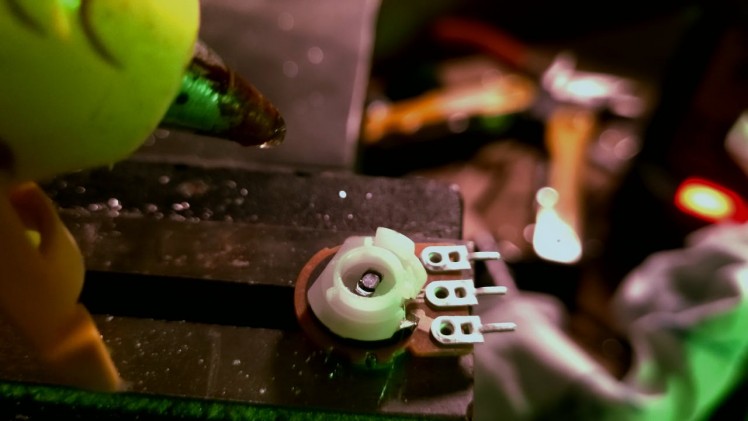

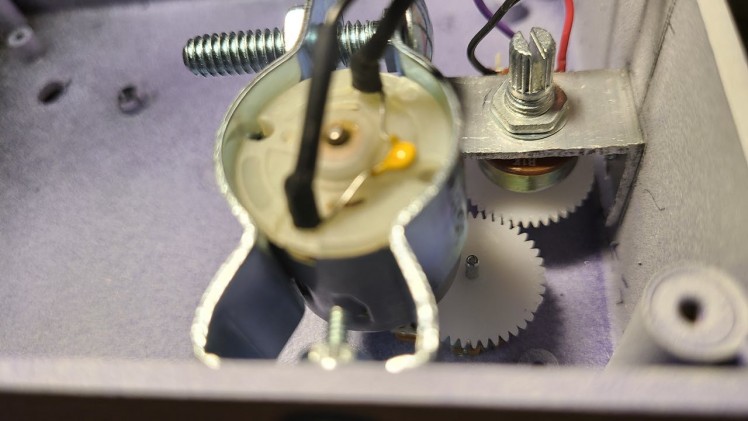
Do this with both pots, then mount everything in a case so that the gears are interlocked. Note: I used this to mount the motor to the side of the case. I also made an angle bracket to mount one of the pots inside the case - it would be confusing to the user if there were 2 knobs doing the same thing on the outside!
Wiring
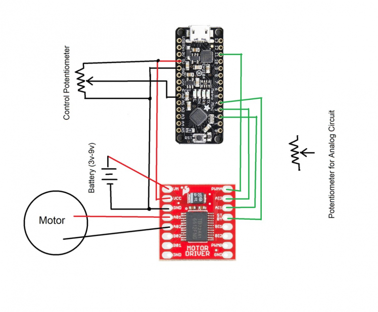
I used a Sparkfun Motor Driver to drive the motor in both directions. See the diagram below.
Software
Find the code at the git repository. I wrote my own PID library that you're free to use, though I know there are others available that people like to use.
I wrote a simple program that reads in the position of the control pot. The user can send the character 's' over serial connection, and the current position will be saved. Then the user can move the pots manually as needed again. They can also send the character 'a' and the pots will be moved by the motor back to the saved position. Once it gets within a set range, the motor will stop and manual control is available again.
I mentioned that the motor struggles to turn this load. Because of this, I hardcoded a minimum PWM value needed to turn the motor. Of course, the PID controller will sometimes calculate a value below this minimum. This means that I undermine the PID calculations. Because of this, some amount of overshoot is unavoidable in this system. I tried making some mechanical changes, described in the video below, to overcome this, but I wasn't able to succeed with that parts available. In the end, I decided that for my purposes, the overshoot isn't a big deal.
Updated Mechanical Design
It has been a few weeks since I published this project, and I have decided to revisit it and improve the design. I remembered that there are dual-gang pots out there already - two potentiometers connected to a single shaft. Using one of these eliminates 1/3 of my initial design. I only need a dual gang pot and a motor.
I chose Bourns brand pots and discovered that the bottom of them is a hexagonal hole.
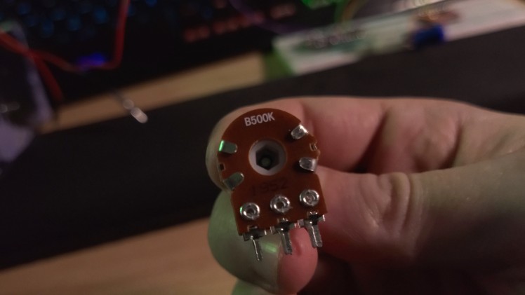
So I modeled and 3D printed a piece that fits that hole and that has its own hold to insert a 2mm shaft for adding gears.
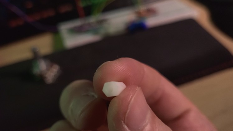
See the second video for more info about the construction of this new potentiometer.


