Esp32 Bluetooth Low Energy Midi Footswitch
About the project
An open-source fully programmable BLE MIDI footswitch
Project info
Difficulty: Moderate
Platforms: Arduino, Everything ESP, Espressif, JLCPCB
Estimated time: 3 hours
License: GNU General Public License, version 3 or later (GPL3+)
Items used in this project
Hardware components
View all
Story
ESP32 BLUETOOTH LOW ENERGY MIDI FOOTSWITCH
With this project you'll build your own footswitch MIDI controller which is connected to your PC via a Bluetooth Low Energy connection!
11/01/2023 UPDATE
Three new versions of the code
• BLE with 6 banks
• Wi-Fi connection (rtpMIDI) with 6 banks [connection instructions on GitHub]
•Wi-Fi connection (rtpMIDI) with 6 banks and physical MIDI output
See its functions and how it works here:
You'll need:
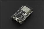
• An ESP32 board with BLE (I used an Az-Delivery ESP32 board)
• N.O. switches (I used two momentary and one latching switch)
• Encoders with switches (just the encoders, not the breakout board version)
• TRS female jack
• LEDs (3 for the banks, use more if you add planning to add more banks, and one for the connection LED) and their 220 Ohm resistors
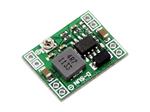
• Step-down DC module to power the board if you want to use a DC power supply
• Expression pedal (if you want to use it)
• External 2-way footswitch (with N.O. switches)
• Arduino IDE (ver. 2, I had problems compiling with version 1.8)
Instructions
I used Arduino IDE and flashed the board as an ESP32 Dev Kit Module.
All the switches have one end to the board and one end to ground.
The pedal sends MIDI CCs and it has 3 banks, each one of the bank has different values for the right and left switches. More banks can be added mapping the switches to other CCs by changing the code.
The switches can be programmed to respond to single, double and long press clicks thanks to the avdweb_Switch library. No debounce is needed.
The encoders are not the version with the breakout board and the 10K resistors, they are just the encoder itself. Their function is implemented with the AiEsp32Rotary library by using internal pullup resistors and ISRs.
Thanks to this strategy and the implementation using these libraries, the parts count is low.
The expression pedal TRS jack is defined as:
•TIP -> Vcc (3V3)
•RING -> pin on the board (PIN_VOLUME)
•SLEEVE -> Gnd
The aux TRS jack is defined as:
•TIP -> aux 1 pin on the board (aux1in)
•RING -> aux 2 pin on the board (aux2in)
•SLEEVE -> Gnd
The pin mapping can be checked in the Arduino code and is the following:
#define buttonup 33
#define buttondown 25
#define buttonleft 27
#define buttonright 26
#define buttonharmony 2

#define auxin1 18
#define auxin2 19

#define dataenc1 17
#define clkenc1 5
#define dataenc2 4
#define clkenc2 16
#define ROTARY_ENCODER_STEPS 4

#define PIN_VOLUME 32

#define ledmode1 12
#define ledmode2 13
#define ledmode3 14
#define ledconn 23
You can change it according to the board you're using.
Thanks to
• MicroMidi for the inspiration -> https://github.com/MicroMidi/NUX-MIDI-Footswitch
• avandalen for the switch library -> https://github.com/avandalen/avdweb_Switch
• igorantolic for the rotary enc library -> https://github.com/igorantolic/ai-esp32-rotary-encoder
• jeffb42 for his work on how to implement an expression pedal with arduino -> https://www.codeproject.com/Articles/38203/Arduino-Based-MIDI-Expression-Pedal
• lathoub for the Arduino AppleMIDI library -> https://github.com/lathoub/Arduino-AppleMIDI-Library


Leave your feedback...