Led Matrix Display Panel
About the project
This is a light panel made of 5x8 type LED matrices, which can be used together with an Arduino platform for example to display text, data from sensors or other messages we want. LED matrices are recovered from broken electronic boards.
Project info
Difficulty: Moderate
Platforms: Arduino, Elegoo, Espressif
Estimated time: 1 hour
License: GNU General Public License, version 3 or later (GPL3+)
Items used in this project
Hardware components
View all
Software apps and online services
Story
Hello!
My name is Cristian, and I am from Romania. I am a hobbyist worker with electronics. I build homemade PCBs and I like to work with Arduino platforms with microcontrollers.
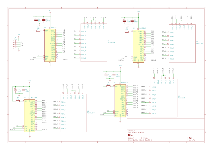
Built according to the models already on the market, by using this circuit, plus a platform with a microcontroller (such as Arduino, ESP32) programmed according to our wishes, we can create a light panel that displays a text. Through the software, you can create a custom text, effects for the text, and you can also display special characters, such as the Celsius temperature sign. What is interesting about this project is the fact that the LED matrices used are of the 5x8 type, a little unusual, unlike the widespread 8x8 matrices that we find on the market, and another thing that should be mentioned is that the 5x8 matrices are recovered from other electronic boards that were broken. So, I don't think you can find another electronic circuit with 5x8 LED matrices like this one. The challenge of this circuit is on the one hand related to the design, hardware development, the correct positioning, and also the software that must be specially created and tested when the electronic board is fully assembled. Each matrix has as a driver a MAX7219, widely used in circuits with LEDs and other displays.
This panel with LED matrices can be used together with an Arduino platform, to which you can add a Bluetooth shield, for example HC05, thus, you can insert the desired text to be displayed directly from a mobile phone, for example. Or, you can use a platform from Expressif, which already incorporates Bluetooth or Wi-Fi technology. Besides these, we can add other modules to the circuit, such as a Real Time Clock, or various sensors, and the measured values can be displayed as we wish on the LED panel.
Bill of Materials
"Component Count:" "21"
"Ref" "Value"
"C1" "10uF"
"C2" "100nF"
"C3" "10uF"
"C4" "100nF"
"C5" "10uF"
"C6" "100nF"
"C7" "10uF"
"C8" "100nF"
"J1" "Pins"
"R1" "27k"
"R2" "27k"
"R3" "27k"
"R4" "27k"
"U1" "MAX7219"
"U2" "Matrix_5x8"
"U3" "MAX7219"
"U4" "Matrix_5x8"
"U5" "MAX7219"
"U6" "Matrix_5x8"
"U7" "MAX7219"
"U8" "Matrix_5x8"
Circuit Diagram


