How To Build A Line Follower Robot With Arduino
About the project
Learn how to create a Line Follower Robot using Arduino UNO, L293D Motor Driver IC and Line sensors
Project info
Difficulty: Easy
Platforms: Arduino
Estimated time: 3 hours
License: Apache License 2.0 (Apache-2.0)
Items used in this project
Story
A line follower robot is an autonomous vehicle that detects and follows a predefined path, usually a black line on a white surface (or vice versa). The robot uses sensors to detect the line and adjusts its movement to stay on track. Line followers have real-world applications in logistics, manufacturing, and more.

Working of a Line Follower Robot
A line follower robot operates by detecting and following a black line on a surface. The detection mechanism leverages the contrast between light absorption and reflection properties of surfaces: black surfaces absorb most of the light, while white surfaces reflect almost all of it. This principle forms the foundation for line-detecting sensors like IR sensors, LDRs, or specialized line sensors.
How Line Sensors Work
Line sensors, used for high precision in such robots, consist of two main components:
- IR Emitter (LED): Continuously emits infrared light.
- IR Receiver (Photodiode): Detects the reflected infrared light.
When the emitted IR light encounters a white surface, it reflects back strongly and is captured by the receiver. Conversely, when the light hits a black line, it is absorbed, and little to no light reaches the receiver. This difference allows the robot to identify the line's position and adjust its movement accordingly.
By processing signals from these sensors, the robot determines whether it is on the line or has deviated, enabling it to steer accurately along the desired path.
Assembling the Arduino-based Line Follower Robot
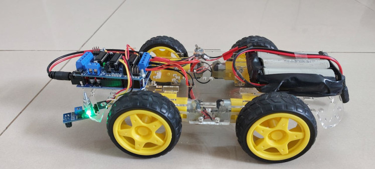
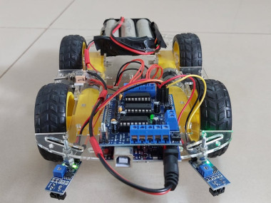
Watch the following video to learn how to assemble the robot.
Circuit Diagram of Line Follower Robot
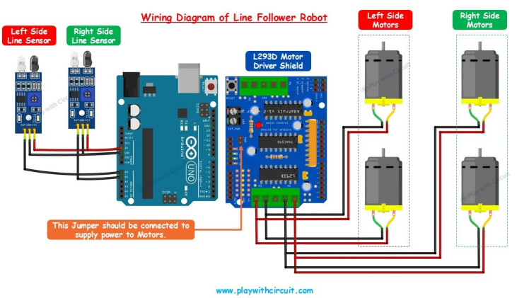
Here is the circuit diagram:

The circuit for the line follower robot is divided into four main components: two IR sensors, an L293D motor driver shield, four 12V BO motors, and an Arduino board. While not shown in the diagram, a 12V power supply is connected to the Arduino to power the entire system. The motor driver shield is mounted directly on top of the Arduino board for seamless connectivity.
The IR sensors are connected as follows: their VCC and Ground pins are wired to the corresponding VCC and Ground pins of the Arduino. The analog output of the left Line sensor is connected to the analog input pin A0, while the right Line sensor's analog output is connected to A1 of the Arduino.
For the motors, the two left-side motors are connected in parallel and linked to the motor driver shield's port M3. Similarly, the right-side motors are connected in parallel to the port M4 of the motor driver shield.
Code
Upload the code to your Arduino.
/*
Library used: Adafruit Motor Shield library V1 version: 1.0.1
For this code to run as expected:
1.The centre to centre distance between the Line sensors should be 11 to 11.5 cm
2. The width of black tape should be 4.8 to 5 cm
3. The distance of the sensor LED from the flat ground surface should be 2 cm.
*/
#include <AFMotor.h>
// MACROS for Debug print, while calibrating set its value to 1 else keep it 0
#define DEBUG_PRINT 0
// MACROS for Analog Input
#define LEFT_IR A0
#define RIGHT_IR A1
// MACROS to control the Robot
#define DETECT_LIMIT 300
#define FORWARD_SPEED 60
#define TURN_SHARP_SPEED 150
#define TURN_SLIGHT_SPEED 120
#define DELAY_AFTER_TURN 140
#define BEFORE_TURN_DELAY 10
// BO Motor control related data here
// Here motors are running using M3 and M4 of the shield and Left Motor is connected to M3 and Right Motor is connected to M4 using IC2 of the shield
AF_DCMotor motorL(3);  // Uses PWM0B pin of Arduino Pin 5 for Enable
AF_DCMotor motorR(4);  // Uses PWM0A pin of Arduino Pin 6 for Enable
// variables to store the analog values
int left_value;
int right_value;
// Set the last direction to Stop
char lastDirection = 'S';
void setup() {
#if DEBUG_PRINT
Serial.begin(9600);
#endif
// Set the current speed of Left Motor to 0
motorL.setSpeed(0);
// turn on motor
motorL.run(RELEASE);
// Set the current speed of Right Motor to 0
motorR.setSpeed(0);
// turn off motor
motorR.run(RELEASE);
// To provide starting push to Robot these values are set
motorR.run(FORWARD);
motorL.run(FORWARD);
motorL.setSpeed(255);
motorR.setSpeed(255);
delay(40);  // delay of 40 ms
}
void loop() {
left_value = analogRead(LEFT_IR);
right_value = analogRead(RIGHT_IR);
#if DEBUG_PRINT
// This is for debugging. To check the analog inputs the DETECT_LIMIT MACRO value 300 is set by analysing the debug prints
Serial.print(left_value);
Serial.print(",");
Serial.print(right_value);
Serial.print(",");
Serial.print(lastDirection);
Serial.write(10);
#endif
// Right Sensor detects black line and left does not detect
if (right_value >= DETECT_LIMIT && !(left_value >= DETECT_LIMIT)) {
turnRight();
}
// Left Sensor detects black line and right does not detect
else if ((left_value >= DETECT_LIMIT) && !(right_value >= DETECT_LIMIT)) {
turnLeft();
}
// both sensors doesn't detect black line
else if (!(left_value >= DETECT_LIMIT) && !(right_value >= DETECT_LIMIT)) {
moveForward();
}
// both sensors detect black line
else if ((left_value >= DETECT_LIMIT) && (right_value >= DETECT_LIMIT)) {
stop();
}
}
void moveForward() {
if (lastDirection != 'F') {
// To provide starting push to Robot when last direction was not forward
motorR.run(FORWARD);
motorL.run(FORWARD);
motorL.setSpeed(255);
motorR.setSpeed(255);
lastDirection = 'F';
delay(20);
} else {
// If the last direction was forward
motorR.run(FORWARD);
motorL.run(FORWARD);
motorL.setSpeed(FORWARD_SPEED);
motorR.setSpeed(FORWARD_SPEED);
}
}
void stop() {
if (lastDirection != 'S') {
// When stop is detected move further one time to check if its actual stop or not, needed when the robot turns
motorR.run(FORWARD);
motorL.run(FORWARD);
motorL.setSpeed(255);
motorR.setSpeed(255);
lastDirection = 'S';
delay(40);
} else {
// When stop is detected next time then stop the Robot
motorL.setSpeed(0);
motorR.setSpeed(0);
motorL.run(RELEASE);
motorR.run(RELEASE);
lastDirection = 'S';
}
}
void turnRight(void) {
// If first time Right Turn is taken
if (lastDirection != 'R') {
lastDirection = 'R';
// Stop the motor for some time
motorL.setSpeed(0);
motorR.setSpeed(0);
delay(BEFORE_TURN_DELAY);
// take Slight Right turn
motorL.run(FORWARD);
motorR.run(BACKWARD);
motorL.setSpeed(TURN_SLIGHT_SPEED);
motorR.setSpeed(TURN_SLIGHT_SPEED);
} else {
// take sharp Right turn
motorL.run(FORWARD);
motorR.run(BACKWARD);
motorL.setSpeed(TURN_SHARP_SPEED);
motorR.setSpeed(TURN_SHARP_SPEED);
}
delay(DELAY_AFTER_TURN);
}
void turnLeft() {
// If first time Left Turn is taken
if (lastDirection != 'L') {
lastDirection = 'L';
// Stop the motor for some time
motorL.setSpeed(0);
motorR.setSpeed(0);
delay(BEFORE_TURN_DELAY);
// take slight Left turn
motorR.run(FORWARD);
motorL.run(BACKWARD);
motorL.setSpeed(TURN_SLIGHT_SPEED);
motorR.setSpeed(TURN_SLIGHT_SPEED);
} else {
// take sharp Left turn
motorR.run(FORWARD);
motorL.run(BACKWARD);
motorL.setSpeed(TURN_SHARP_SPEED);
motorR.setSpeed(TURN_SHARP_SPEED);
}
delay(DELAY_AFTER_TURN);
}
To learn how to calibrate and troubleshoot line follower Robot checkout this detailed article: Line Follower Robot using Arduino


Leave your feedback...