Hacking Qualcomm With Just A Few Resistors
About the project
Following Shahariar Hossain's project on hacking qualcomm with a ATtiny85, I took his advice to just try it with resistors.
Project info
Difficulty: Easy
Platforms: Electric Imp, Qualcomm
Estimated time: 1 hour
License: GNU General Public License, version 3 or later (GPL3+)
Items used in this project
Story
I have got a nice powerbank with QC 3.0 support. Only a switch to change to different voltage is missing.So I searched for information how to change the voltage and found Shahariar's project, see: https://www.electromaker.io/project/view/hacking-qualcomm-quick-charge-qc-2030-with-attiny85
I followed his hint to just try it without a microcontroller. The thing is, you have to create two voltage on the USB Data lines D+, D-, to change the output voltage.
D+ D- Output0.6V 0.6V 12V3.3V 0.6V 9V3.3V 3.3V 20V0.6V Gnd 5V (default)
I needed 12 V, so 0.6V on each Data line. Shahariar used 3.3V (mainly for the microcontroller) generated by a regulator. He got 0.6V from a voltage divider with two resistors. My idea was just to use the 5V from the USB power and also a voltage divider. I like it short and simple, so my approach was to take around the same current as Shariar in his project: 3.3V / 12.2kOhm = 0.27mA not so much current.
The resistance for my voltage divider is: 5V / 0.27mA = 18kOhm. The current in a voltage divider is the same in both resistors, the first resistor is therefore 0.6V / 0.27mA = 2.2kOhm. The second one, arithmetical ~ 16kOhm, I choosed 15kOhm.
This is the wiring scheme:
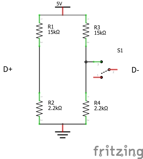
As you can see in my project picture, this approach works perfect at least for 12V. Even with 20V the voltage divider consumes only 11mA.
Just plug-in the voltage divider arrangement, the Switch position is not important, either on or off. First you get 5V, because you have to init the QC handling, just wait 2-3 sec and press the switch. If you get 12V, great. Otherwise wait 2-3 sec and press the switch again, now you should get the 12V.


Leave your feedback...