Gesture Recognition Using Raspberry Pi Pico And Edge Impulse
About the project
In this project, we will learn how to write a Hand Gesture recognition program for Raspberry Pi Pico using Edge Impulse platform.
Project info
Difficulty: Moderate
Platforms: Arduino, Raspberry Pi, Edge Impulse
Estimated time: 3 hours
License: GNU General Public License, version 3 or later (GPL3+)
Items used in this project
Story
The way of running ML on a microcontroller is called Embedded ML or TinyML. So, In this tutorial, we will learn how to use the MPU6050 Accelerometer and Gyroscope sensor with the Raspberry Pi Pico and the TinyML Edge Impulse web platform in order to implement a Hand Gesture recognition program. Using Edge Impulse, you can now quickly collect real-world sensor data, train an ML model on the data in the cloud, and deploy the model back to an edge device.
To prepare our environment, we must install the SDK (Software Development Kit), henceforth SDK, which is allows your operating system to interact with the RaspBerry Pi Pico once you connect it to a USB port. The SDK can be built on platforms such as Raspberry Pi products (4B or 3B), x86 Linux, Windows, Mac, and more. Fortunately for us, Raspberry Pi Foundation released SDK (Software Development Kit) for C / C++ programming languages to develop applications for RP2040 based boards.
Build and debug can be done from the command line, and you can also use Visual Studio Code, Eclipse and CLion Integrated Development Environments(IDE). I recommend Visual Studio Code as the development environment, because it works cross-platform under Linux, Windows, and macOS and has good plugin support for debugging. You can take a look at Chapter 9(9.1.2) of the Getting Startedguide provided by Raspberry Pi Foundation.
Hardware RequirementsFor this article I used the following hardware:
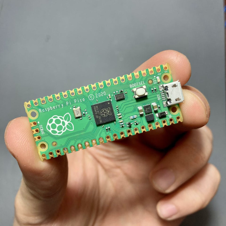
- Raspberry Pi Pico
- MPU6050 sensor. MPU6050 sensor module is an integrated 6-axis Motion tracking device. The MPU-6050 devices combine a 3-axis gyroscope, a 3-axis accelerometer, Digital Motion Processor and a Temperature sensor all on a single chip.
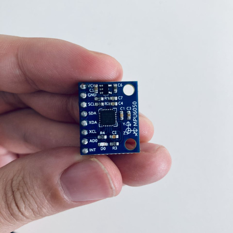
Accelerometer senses axis orientation where as gyroscope senses angular orientation. They are used in conjunction with magnetometer. This combined sensor system consisting of accelerometer, gyroscope and magnetometer is known as IMU (Inertial Measurement Unit).
Additional requirements is to have basic understanding of software development and application using C++. I will be using Edge Impulse, an online development platform for machine learning on edge devices. There you need to sign up for a free account. Log in to your account and name your new project by clicking on the title. I call it Hand Gesture Recognition.
Building the Blinking LED application using VS Code for macOSWhen you’re writing software for hardware, the first program that gets run in a new programming environment is typically blinking LED in your board. Let us see how to Program Raspberry Pi Pico using C Programming Language and VS Code.
Open the terminal and create a directory called pico. Enter the following commands one after the other.
cd ~/
mkdir pico
cd pico
and install SDK,
git clone -b master --recurse-submodules https://github.com/raspberrypi/pico-sdk.gitIt lasts for about 15-20 minutes to clone and finish executing a command, so feel free to take a break.
Also, export the path for pico-sdk using the following command.
nano ~/.zshrcAdd the following line:
export PICO_SDK_PATH="$HOME/pico/pico-sdk"To build projects you’ll need CMake, a cross-platform tool used to build the software, and the GNU Embedded Toolchain for Arm.
brew install cmake
brew tap ArmMbed/homebrew-formulae
brew install arm-none-eabi-gcc
Download and run Microsoft Visual Studio Code.
Click on the Extensions icon. Enter CMake Tools in the search field and install it.
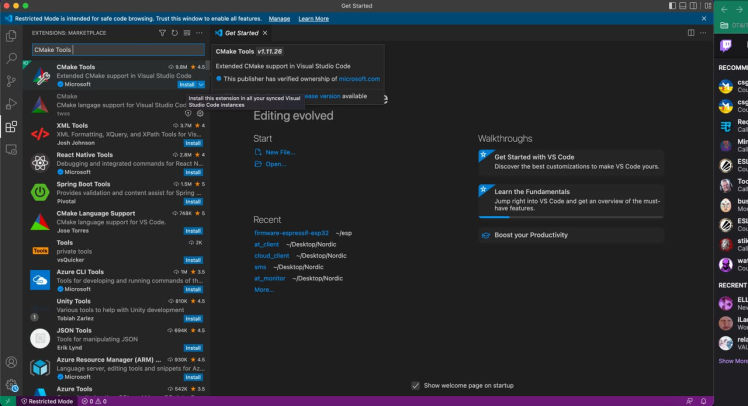
After installation reload your Microsoft Visual Studio Code.
Then on terminal run
cd ..
git clone -b master https://github.com/raspberrypi/pico-examples.git
Open the pico-examples folder in VS Code.
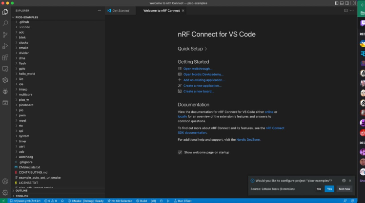
The CMake extension will ask you configure pico-examples projects. Click on Yes. Then click on the No Kit Selected option at the bottom of the Status Bar. Then select GCC for arm-none-eabi option.
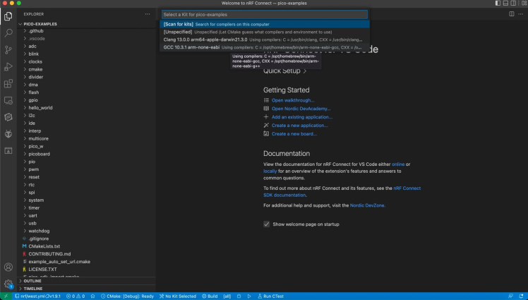
Click the Build button in the status bar. This will call make to build your project. You should see new, compiled binaries appear in the build folder.
If everything goes correctly, you should see the following output:
[build] Build finished with exit code 0The compilation generates the binary file of your program in UF2 format. The UF2 format is intended for flashing a microcontroller connected as USB mass storage on your PC. The easiest method of uploading your compiled program is to use the UF2 bootloader that comes with the Pico, which will mount the Pico as an USB Mass Storage Device. Then we can simply drag-and-drop the blink.uf2 file.
Plug-in the micro USB cable to Raspberry Pi Pico and hold the BOOTSEL button while plugging the USB cable into the Pico. Once the USB cable is attached, release the BOOTSEL button.
Navigate into your build folder. Drag and drop the blink.uf2 and paste into the RPI-RP2 drive.
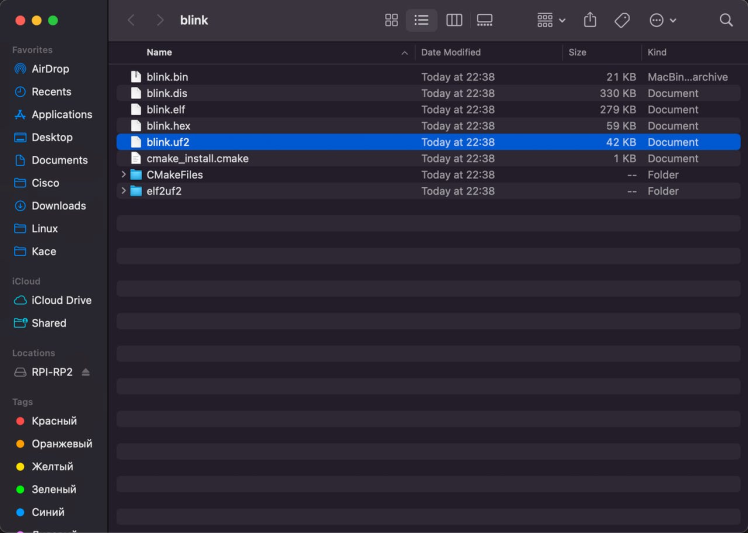
Once the program is copied to the Raspberry Pi Pico, the Pico should automatically reboot and it runs immediately. The Raspberry Pi Pico LED should be flashing.
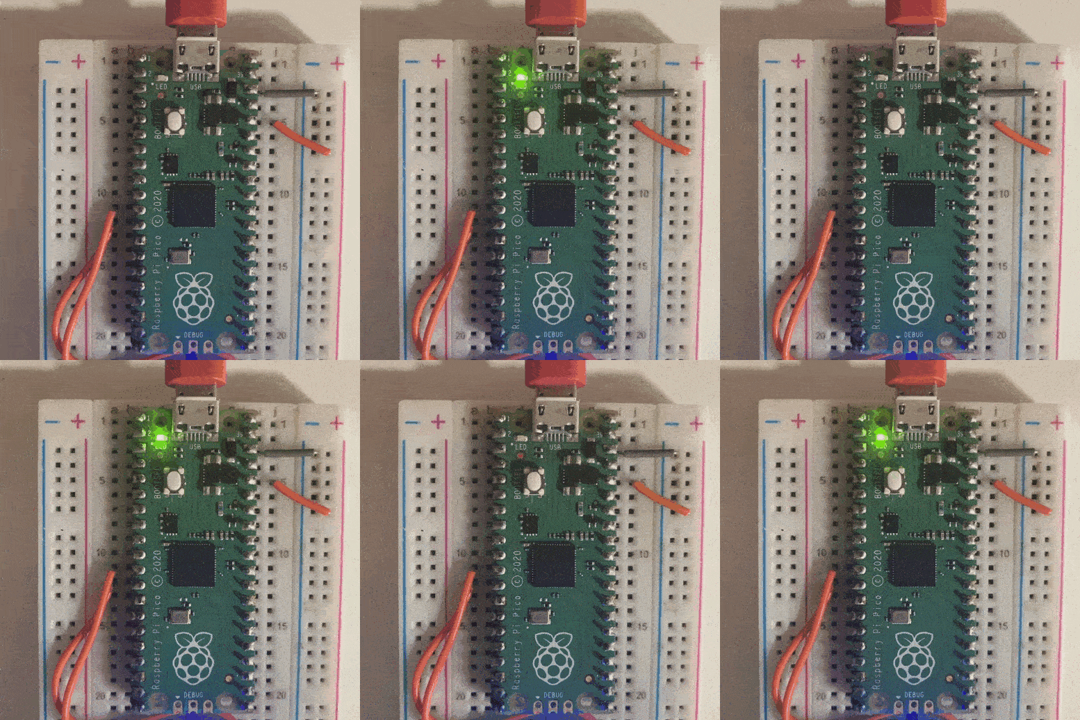
That’s all about for programming the Raspberry Pi Pico using Microsoft Visual Studio Code. If you’ve got this far, you’ve built and deployed your very first C program to your Raspberry Pi Pico. Well done! The next step is probably going to be Gesture recognition Using Raspberry Pi Pico.
Setting-Up the C/C++ SDK for Raspberry Pi Pico on Linux(optional)It's strongly recommended to use Linux machines in order to write programs for the RP2040-based devices. If you don't have an existing Linux physical machine, you can create a virtual machine. There is always option of building applications using a virtual machine. It is available on both PC and Mac, (I’m using an Ubuntu 22.04 release in a VM on Mac M1 myself as a dedicated environment using solution from UTM). I would suggest using a free Virtual Machine software like VMWare and Virtualbox and installing Linux on there.
Open the terminal and create a directory called pico. Enter the following commands one after the other.
cd ~/
mkdir pico
cd pico
Then clone the pico-sdk and pico-examples git repositories.
git clone -b master https://github.com/raspberrypi/pico-sdk.git
cd pico-sdk
git submodule update --init
cd ..
git clone -b master https://github.com/raspberrypi/pico-examples.git
and instal the toolchain,
sudo apt update
sudo apt install cmake gcc-arm-none-eabi libnewlib-arm-none-eabi build-essential
Finally, implement the Blink example and go further.
Reading MPU6050 Sensor Data Using Raspberry Pi PicoTo read accelerometer data from the MPU6050sensor, we'll use an example based on the pico examples. Open the pico-examples folder in VSCode. Navigate to I2C folder and find mpu6050_i2c example.
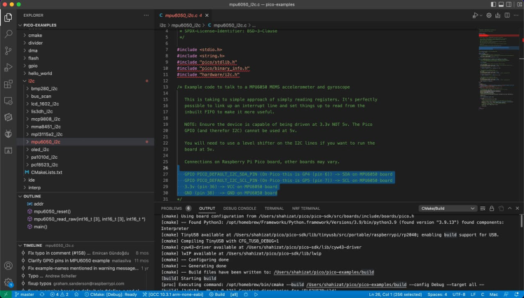
We need to open the CMakeLists file and tell the compiler that we are going to be using the USB output and to disable the UART output. This can be done with the following:
# Enable usb output, disable uart output
pico_enable_stdio_usb(mpu6050_i2c 1)
pico_enable_stdio_uart(mpu6050_i2c 0)
The connections are pretty easy, see the image below with breadboard circuit schematic. It is important to note that, RP2040 microcontrollers use 3.3V for GPIO.
GPIO PICO_DEFAULT_I2C_SDA_PIN (On Pico this is GP4 (pin 6)) -> SDA on MPU6050 board
GPIO PICO_DEFAULT_I2C_SCL_PIN (On Pico this is GP5 (pin 7)) -> SCL on MPU6050 board
3.3v (pin 36) -> VCC on MPU6050 board
GND (pin 38)  -> GND on MPU6050 board
Make all the connections as per the above connection. Here's my setup:
Blinking the onboard LED
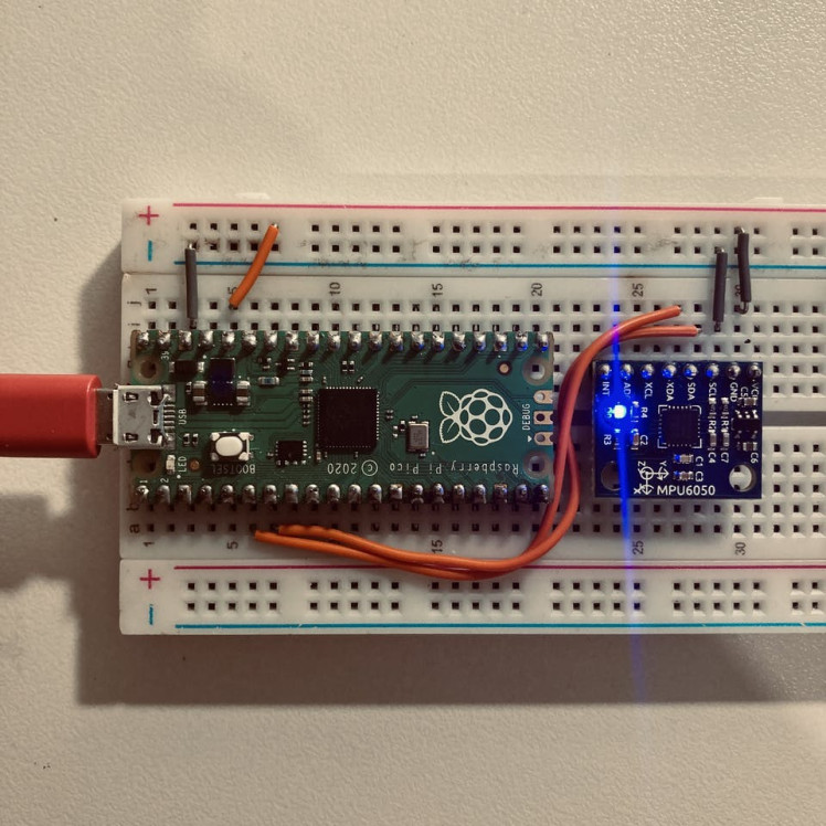
Blinking the onboard LED
With that, you’re now ready to get it working.
To display the output, you can use the minicom. I will be using screen since I am on a Mac OS. Open a terminal program and connect it to the serial port of your Pico with a baud rate of 115200 using below command:
screen /dev/tty.usbmodem1101 115200or run
edge-impulse-run-impulse --rawThe following serial UART output will be displayed in the terminal:
Acc. X = -60, Y = 372, Z = 32767
Gyro. X = -100, Y = 151, Z = 79
Temp. = 25.377059
Acc. X = -96, Y = 484, Z = 32767
Gyro. X = -103, Y = 190, Z = 79
Temp. = 25.471176
Acc. X = -96, Y = 400, Z = 32767
Gyro. X = -94, Y = 167, Z = 83
Temp. = 25.518235
Acc. X = -44, Y = 392, Z = 32767
Gyro. X = -75, Y = 132, Z = 62
Temp. = 25.518235
Acc. X = 64, Y = 308, Z = 32767
Gyro. X = -70, Y = 212, Z = 69
Temp. = 25.471176
Acc. X = -88, Y = 324, Z = 32767
Gyro. X = -105, Y = 194, Z = 76
Temp. = 25.518235
Raw data is output from -32767 to + 32767.
However, while two of the axis work nicely, sometimes I'm having issues with the third axis. The roll and pitch are good, but the Z-axis yaw has a strange value, which is also know as gravity direction. So, we know that the MPU-6050 measures acceleration over the X, Y an Z axis and Z-axis suffers drift in the MPU6050.
Collect a dataset and train the model using Edge Impulse studioEdge Impulse is a platform that enables developers to easily train and deploy deep learning models on embedded devices. Now, let’s jump straight to action.
Login to your account and create a new project.
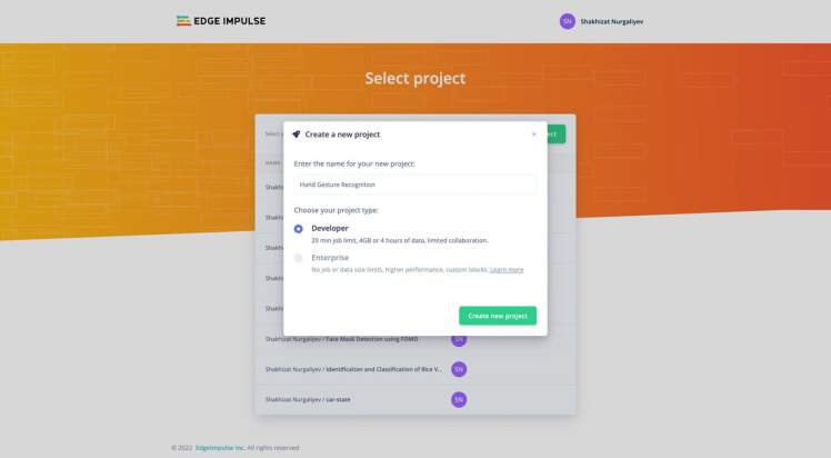
Select accelerometer data then Let's get started button.
A quick way of getting data from devices to Edge Impulse studio is using the Data forwarder. To put simply, it lets you forward data collected over a serial interface to the studio.
You can run the edge-impulse-data-forwarder from the terminal.
edge-impulse-data-forwarderSelect a Hand Gesture Recognition project.
Then, Follow the prompts to log into your Edge Impulse account
Edge Impulse data forwarder v1.15.1
Endpoints:
Websocket: wss://remote-mgmt.edgeimpulse.com
API:  https://studio.edgeimpulse.com/v1
Ingestion: https://ingestion.edgeimpulse.com
[SER] Connecting to /dev/tty.usbmodem101
[SER] Serial is connected (E6:60:38:B7:13:27:B5:32)
[WS ] Connecting to wss://remote-mgmt.edgeimpulse.com
[WS ] Connected to wss://remote-mgmt.edgeimpulse.com
[SER] Detecting data frequency...
[SER] Detected data frequency: 105Hz
[SER] Sampling frequency seems to have changed (was 9Hz, but is now 105Hz), re-configuring device.
The 3-axis data is detected and I named it as accX, accY, accZ respectively. This represents the format in which data is streamed from the accelerometer sensor.
accX, accY, accZWhat name do you want to give this device?
picoOn Edge Impulse, the device has been recognized successfully.

Next, go to the Data acquisition tab, and in the Record new data window, select your device, set the label to idle, the sample length to 10000, the sensor to Built-in accelerometer. This indicates that you want to record data for 10 seconds, and label the recorded data as idle. You can later edit these labels if needed.
Click Start sampling to acquire the raw data from the pico.
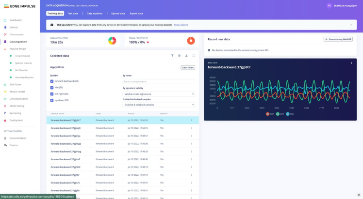
I have 4 classes (ilde, up-down,left-right and forward-backward movements.) Try to collect for each class not less than 15 samples.
After collecting enough datasets, you’re now ready to design and build your ML model in the Edge Impulse Studio. To do so, under the Impulse design menu, click Create impulse.
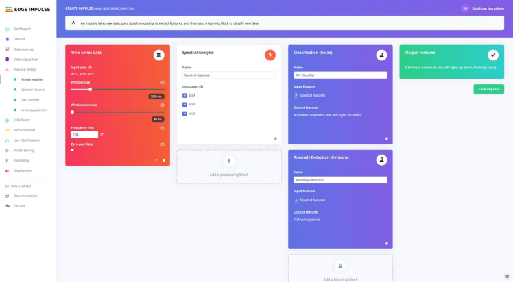
For this tutorial, we’ll use the Spectral Analysis processing block. This block applies a filter, performs spectral analysis on the signal, and extracts frequency and spectral power data. Once the impulse pipeline is complete, click Save Impulse.
Next, under the Spectral features tab we will keep the default parameters. Click Save parameters.
Then, Click Generate features to start the process.
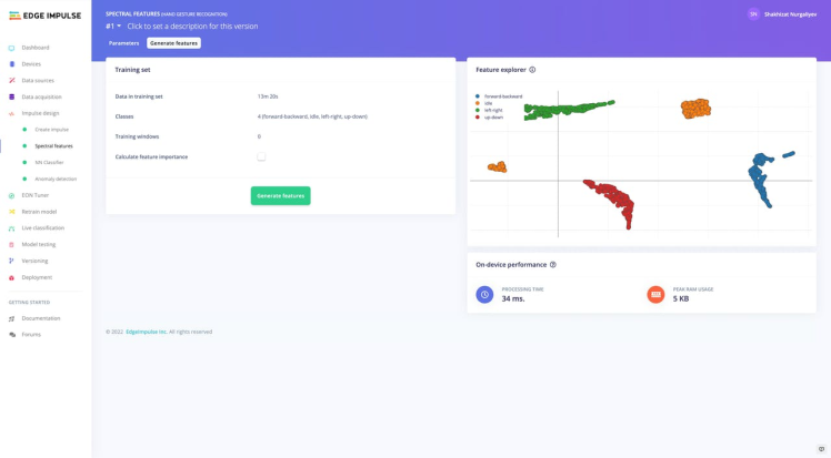
So, it’s time to start training a neural network. Next, click on the NN Classifier and set the Number of training cycles to 30 and the Learning rate to 0.0005. Next, click on Start training to train the ML model, this might take some time to complete depending on the size of your dataset.
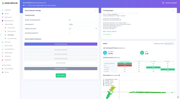
The model should also be able to achieve an accuracy of at least 70%. In general, if you have 100% train accuracy, you've probably massively overfit.
Navigate to Anomaly Detection tab and Select Suggested Axes and finally click start training.
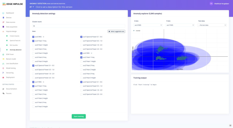
Then go to either Live classification or model testing in the left menu in order to test it.
At this point, the model is trained and tested and we can move on to deploying to our hardware.
Deploying the ML model to your Raspberry Pi Pico board is really simple, just navigate to Deployment on the left menu. In the Create library section, click on C++ library and then, on the bottom, click on the Build button.
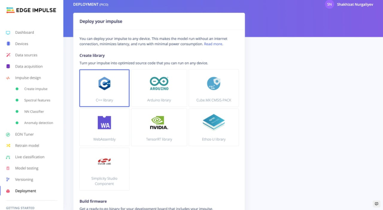
Before converting the model, you need to enable the Edge Optimized Neural EON compiler, which allows running with 25-55% less memory and up to 35% less flash compared to TensorFlow Lite for microcontrollers neural network while maintaining the same accuracy.
Clone a repository using the command line below:
git clone https://github.com/shahizat/example-standalone-inferencing-pico.gitThen, follow the instructions in this link. You can view my public edge impulse project here.
Run real-time inference using below command.
edge-impulse-run-impulse --rawOpen the serial monitor, perform some gestures, and see some inferences. You should see some timing results along with the output predictions.
Predictions (DSP: 34 ms., Classification: 3 ms., Anomaly: 2 ms.):
-> forward-backward: 1.0000
-> idle: 0.0000
-> left-right: 0.0000
-> up-down: 0.0000
anomaly score: -0.468
Predictions (DSP: 34 ms., Classification: 3 ms., Anomaly: 2 ms.):
-> forward-backward: 0.0000
-> idle: 1.0000
-> left-right: 0.0000
-> up-down: 0.0000
anomaly score: 0.001
Finally, the test video is as follows:
Congratulations! You just have implemented a system that can recognize hand gestures using Raspberry Pi Pico and Edge Impulse studio.
Very special thanks to Marcelo Rovai and Dmitry Maslov for inspiring me to make this project possible.
ReferencesCheck out the links below:
- Pi Day: The Taste of Raspberry Pi Pico
- CarAccidentDetection-EdgeImpulse-Pico
- Difference between Accelerometer and Gyroscope | Accelerometer vs Gyroscope
- Arduino and MPU6050 Accelerometer and Gyroscope Tutorial
- TinyML - Motion Recognition Using Raspberry Pi Pico
- Machine Learning Inference on Raspberry Pico 2040 via Edge Impulse
- MPU6050 interfacing with Raspberry using I2C
- Getting started with Raspberry Pi Pico


Leave your feedback...