
Ultra Tinyml: Machine Learning For 8-bit Microcontroller
About the project
How to create a gesture recognition system with Arduino and Neuton TinyML
Project info
Difficulty: Moderate
Platforms: Arduino, SparkFun, Neuton Tiny ML
Estimated time: 1 hour
License: GNU Lesser General Public License version 3 or later (LGPL3+)
Items used in this project
Hardware components
Story
Introduction
In this project, I will show an easy way to get started with TinyML: implementing a Machine Learning model on an Arduino board while creating something cool: a gesture recognition system based on an accelerometer.
To make the experiment simpler, the system is designed to recognize only two gestures: a punch and a flex movement (in the data science field, a binary classification).
Punch gesture

Punch gesture
Flex gesture

Flex gesture
The biggest challenge of this experiment is trying to run the prediction model on a very tiny device: an 8-bit microcontroller. To achieve this, you can use Neuton.
Neuton is a TinyML framework. It allows to automatically build neural networks without any coding and with a little machine learning experience and embed them into small computing devices. It supports 8, 16, and 32-bit microcontrollers.
The experiment is divided into three steps:
- Capture the training dataset
- Train the model using Neuton
- Deploy and run the model on Arduino
Experiment process flow

Experiment process flow
SetupThe gesture recognition system is composed by:
- A microcontroller:Arduino Mega 2560
- An accelerometer sensor: GY-521 ModuleThis module is built around the InvenSense MPU-6050: a sensor containing, in a single IC, a 3-axis MEMS accelerometer and 3-axis MEMS gyroscope.Its operation is very precise since it contains for each channel an accurate digital converter. It can to capture the values of the X, Y, and Z axes at the same time. Communication with MCU takes place using the I2C interface.
GY-521 is powered with the 5V and GND pins of the Arduino Mega power section, while for data communication the I2C pins are used (Pin 20 and Pin 21).The remaining pins are optional and not useful for this application.
To verify if the GY-521 module is correctly supplied, connect the USB cable of the Arduino board and check if the LED mounted on the sensor board is turning on.
GY-521: LED position
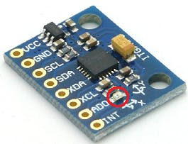
GY-521: LED position
After verifying the sensor power supply, check if the I2C communication is working properly by downloading the Adafruit MPU6050 Arduino library and opening the “plotter” example.
Upload the example sketch on the Arduino board, open the “Serial Plotter” within the Tools menu, set 115200 in the baud drop-down menu, and “shake” the sensor board. The expected result will be the following:
Serial Plotter of MPU6050 plotter example
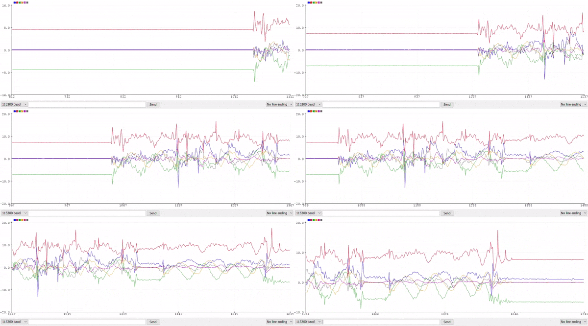
Serial Plotter of MPU6050 plotter example
Now, the system is ready to collect accelerometer and gyroscope data.
1. Capture training dataThe first step to building the predictive model is to collect enough motion measurements.This set of measures is called training dataset and it will be used to train the Neuton neural network builder.
The easiest way to achieve this is to repeat several times the same two motions (punch and flex), by capturing acceleration and gyroscope measurements and storing the result in a file.To do this, you create an Arduino sketch dedicated to sensor data acquisition. The program will acquire the measurements of each motion and will print the sensor measurements output on the serial port console.
You will perform at least 60 motions: 30 for the first movement (punch) and 30 for the second one (flex). For each motion, you will acquire 50 acceleration and 50 gyroscope measures in a 1 second time window (Sampling time: 20ms —50Hz). In this experiment, 60 motions are enough. By increasing the number of motion measurements, you can improve the predictive power of the model. However, a large dataset can lead to an over-fitted model. There is no “correct” dataset size, but a “trial and error” approach is recommended.
The serial port output of the Arduino sketch will be formatted according to Neutontraining dataset requirements.
Below, Arduino program for dataset creation:
- IMU Sensor initialization and CSV header generation:
#define NUM_SAMPLES 50

Adafruit_MPU6050 mpu;

void setup() {
  // init serial port
  Serial.begin(115200);
  while (!Serial) {
    delay(10);
  }
  // init IMU sensor
  if (!mpu.begin()) {
    while (1) {
      delay(10);
    }
  }

  // configure IMU sensor
  // [...]

  // print the CSV header (ax0,ay0,az0,...,gx49,gy49,gz49,target)
  for (int i=0; i<NUM_SAMPLES; i++) {
    Serial.print("aX");
    Serial.print(i);
    Serial.print(",aY");
    Serial.print(i);
    Serial.print(",aZ");
    Serial.print(i);
    Serial.print(",gX");
    Serial.print(i);
    Serial.print(",gY");
    Serial.print(i);
    Serial.print(",gZ");
    Serial.print(i);
    Serial.print(",");
  }
  Serial.println("target");
}- Acquisition of 30 consecutive motions. The start of a motion is detected if the acceleration sum is above a certain threshold (e.g.,2.5 G).
#define NUM_GESTURES    30
#define GESTURE_0       0
#define GESTURE_1       1
#define GESTURE_TARGET  GESTURE_0
//#define GESTURE_TARGET  GESTURE_1

void loop() {
  sensors_event_t a, g, temp;

  while(gesturesRead < NUM_GESTURES) {
    // wait for significant motion
    while (samplesRead == NUM_SAMPLES) {
      // read the acceleration data
      mpu.getEvent(&a, &g, &temp);

      // sum up the absolutes
      float aSum = fabs(a.acceleration.x) +
                   fabs(a.acceleration.y) +
                   fabs(a.acceleration.z);

      // check if it's above the threshold
      if (aSum >= ACC_THRESHOLD) {
        // reset the sample read count
        samplesRead = 0;
        break;
      }
    }

    // read samples of the detected motion
    while (samplesRead < NUM_SAMPLES) {
        // read the acceleration and gyroscope data
        mpu.getEvent(&a, &g, &temp);

        samplesRead++;

        // print the sensor data in CSV format
        Serial.print(a.acceleration.x, 3);
        Serial.print(',');
        Serial.print(a.acceleration.y, 3);
        Serial.print(',');
        Serial.print(a.acceleration.z, 3);
        Serial.print(',');
        Serial.print(g.gyro.x, 3);
        Serial.print(',');
        Serial.print(g.gyro.y, 3);
        Serial.print(',');
        Serial.print(g.gyro.z, 3);
        Serial.print(',');

        // print target at the end of samples acquisition
        if (samplesRead == NUM_SAMPLES) {
          Serial.println(GESTURE_TARGET);
        }

        delay(10);
    }
    gesturesRead++;
  }
}
Firstly, run the above sketch with the serial monitor opened and GESTURE_TARGET set to GESTURE_0. Then, run with GESTURE_TARGET set to GESTURE_1. For each execution, perform the same motion 30 times, ensuring, as far as possible, that the motion is performed in the same way.
Copy the serial monitor output of the two motions in a text file and rename it to “trainingdata.csv”.
2. Train the model with Neuton TinyMLNeuton performs training automatically and without any user interaction.Train a Neural Network with Neuton is quick and easy and is divided into three phases:
- Dataset: Upload and validation
- Training: Auto ML
- Prediction: Result analysis and model download
- First, create a new Neuton solution and name it (e.g., Gesture Recognition).
Neuton: add new solution
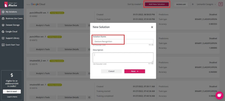
Neuton: add new solution
- Upload CSV training dataset file.
Neuton: upload CSV file
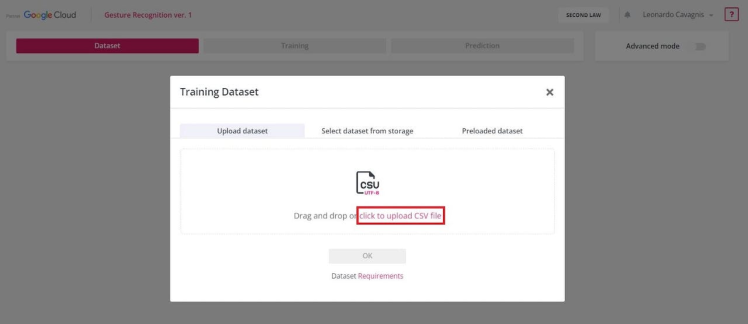
Neuton: upload CSV file
- Neuton validates CSV file according to dataset requirements.
Neuton: dataset validation
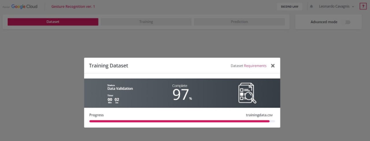
Neuton: dataset validation
- If the CSV file meets the requirements a green check will appear, otherwise, an error message will be shown.
Neuton: validated dataset

Neuton: validated dataset
- Select the column name of the target variable (e.g., target) and click “Next”.
Neuton: target variable
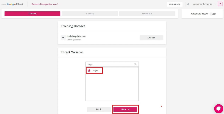
Neuton: target variable
Neuton: dataset content preview
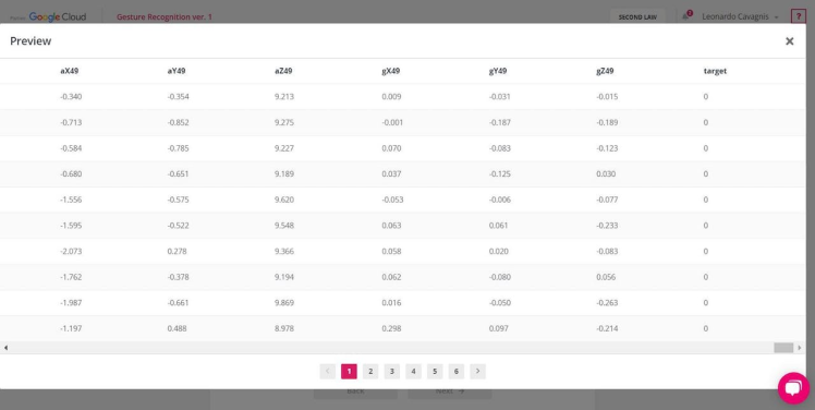
Neuton: dataset content preview
2.2. Training: Auto MLNow, let’s get to the heart of training!
- Neuton analyzes the content of the training dataset and defines the ML task type. With this dataset, the binary classification task is automatically detected.
Neuton: Task type
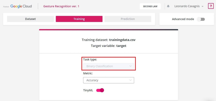
Neuton: Task type
- Metric is used to monitor and measure the performance of a model during training. For this experiment, you use the Accuracy metric: it represents how accurately class is predicted. The higher the value, the better the model.
Neuton: Metric
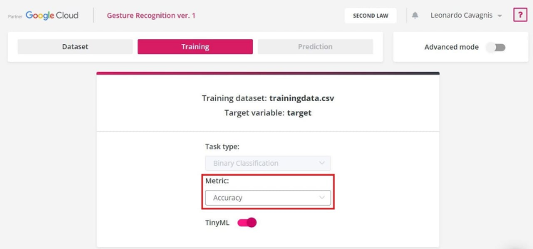
Neuton: Metric
- Enable TinyML option to allow Neuton to build a tiny model for a microcontroller.
Neuton: TinyML option

Neuton: TinyML option
- In the TinyML settings page, select “8-bit” in the drop-down menu and enable the “Float datatype support” option. This, because the microcontroller used in the experiment is an 8-bit MCU with floating-point number support.
Neuton: TinyML settings
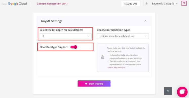
Neuton: TinyML settings
- After pressing the “Start Training” button, you will see the process progress bar and the percentage of completion.
Neuton: Training started
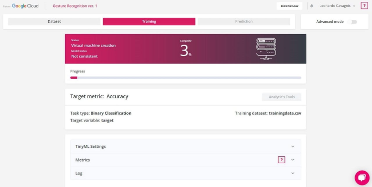
Neuton: Training started
- The first step is data preprocessing. It is the process of preparing (cleaning, organizing, transforming, etc.) the raw dataset to make it suitable for training and building ML models.
- After data preprocessing completion, model training starts. The process can take a long time; you can close the window and come back when the process is finished. During training, you can monitor the real-time model performance by observing model status (“consistent” or “not consistent”) and Target metric value.
Neuton: Data preprocessing complete
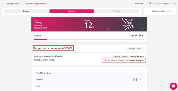
Neuton: Data preprocessing complete
- Upon training is complete, the “Status” will change to “Training completed”. Model is consistent and has reached the best predictive power.
Neuton: Training completed
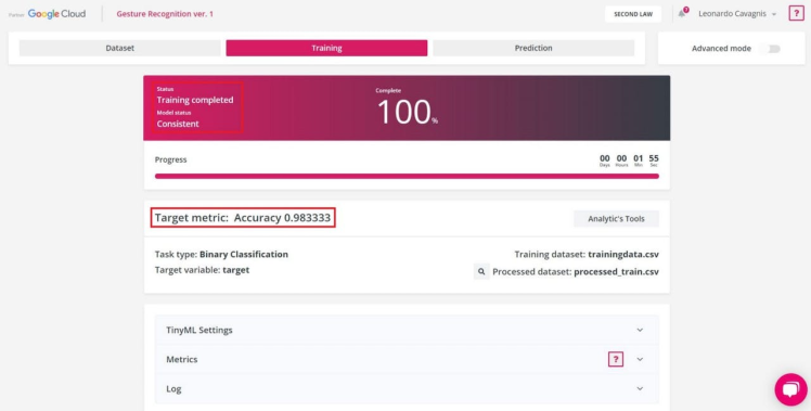
Neuton: Training completed
2.3. Prediction: Result analysis and model downloadNeuton: Training completed
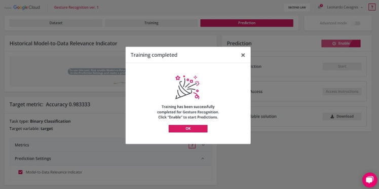
Neuton: Training completed
After the training procedure is completed, you will be redirected to the «Prediction» section. In this experiment, the model has reached an accuracy of 98%. It means that from 100 predicted records, 98 had been assigned to the correct class… that’s impressive!
Moreover, the size of the model to embed is less than 3KB. This is a very small size, considering that the Arduino board in use is 256KB memory size and the typical memory size for an 8-bit microcontroller is 64KB÷256KB.
Neuton: Metrics

Neuton: Metrics
To download the model archive, click on the “Download” button.
Neuton: Prediction tab
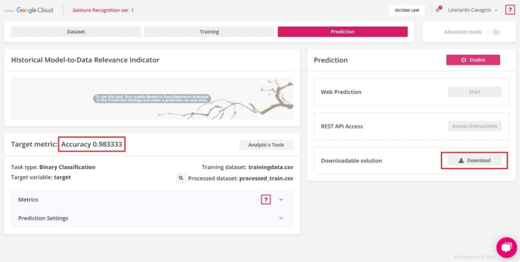
Neuton: Prediction tab
3. Deploy the model on ArduinoThe model archive downloaded from Neuton includes the following files and folders:
- /model:the neural network model in a compact form (HEX and binary).
- /neuton:a set of functions used to perform predictions, calculation, data transferring, result management, etc.
- user_app.c: a file in which you can set the logic of your application to manage the predictions.
First, you modify the user_app.c file adding functions to initialize model and run inference.
/*
 * Function: model_init
 * ----------------------------
 *
 *   returns: result of initialization (bool)
 */
uint8_t model_init() {
   uint8_t res;

   res = CalculatorInit(&neuralNet, NULL);

   return (ERR_NO_ERROR == res);
}

/*
 * Function: model_run_inference
 * ----------------------------
 *
 *   sample: input array to make prediction
 *   size_in: size of input array
 *   size_out: size of result array
 *
 *   returns: result of prediction
 */
float* model_run_inference(float* sample,
                           uint32_t size_in,
                           uint32_t *size_out) {
   if (!sample || !size_out)
      return NULL;
   if (size_in != neuralNet.inputsDim)
      return NULL;

   *size_out = neuralNet.outputsDim;

   return CalculatorRunInference(&neuralNet, sample);
}
After that, you create the user_app.h header file to allow the main application using the user functions.
uint8_t model_init();
float*  model_run_inference(float* sample,
                            uint32_t size_in,
                            uint32_t* size_out);
Below, the Arduino sketch of main application:
- Model initialization
#include "src/Gesture Recognition_v1/user_app.h"

void setup() {
   // init serial port and IMU sensor
   // [...]

   // init Neuton neural network model
   if (!model_init()) {
      Serial.print("Failed to initialize Neuton model!");
      while (1) {
        delay(10);
      }
   }
}- Model inference
#define GESTURE_ARRAY_SIZE  (6*NUM_SAMPLES+1)

void loop() {
   sensors_event_t a, g, temp;
   float gestureArray[GESTURE_ARRAY_SIZE]  = {0};

   // wait for significant motion
   // [...]

   // read samples of the detected motion
   while (samplesRead < NUM_SAMPLES) {
      // read the acceleration and gyroscope data
      mpu.getEvent(&a, &g, &temp);

      // fill gesture array (model input)
      gestureArray[samplesRead*6 + 0] = a.acceleration.x;
      gestureArray[samplesRead*6 + 1] = a.acceleration.y;
      gestureArray[samplesRead*6 + 2] = a.acceleration.z;
      gestureArray[samplesRead*6 + 3] = g.gyro.x;
      gestureArray[samplesRead*6 + 4] = g.gyro.y;
      gestureArray[samplesRead*6 + 5] = g.gyro.z;

      samplesRead++;

      delay(10);

      // check the end of gesture acquisition
      if (samplesRead == NUM_SAMPLES) {
         uint32_t size_out = 0;

         // run model inference
         float* result = model_run_inference(gestureArray,
                                             GESTURE_ARRAY_SIZE,
                                             &size_out);
         // check if model inference result is valid
         if (result && size_out) {
            // check if problem is binary classification
            if (size_out >= 2) {
               // check if one of the result has >50% of accuracy
               if (result[0] > 0.5) {
                  Serial.print("Detected gesture: 0");
                  // [...]
               } else if (result[1] > 0.5) {
                  Serial.print("Detected gesture: 1");
                  // [...]
               } else {
                  // solution is not reliable
                  Serial.println("Detected gesture: NONE");
               }
            }
         }
     }
   }
}/neuton_gesturerecognition
|- /src
| |- /Gesture Recognition_v1
| |- /model
| |- /neuton
| |- user_app.c
| |- user_app.h
|- neuton_gesturerecognition.inoNow, it’s time to see the predictive model in action!
- Verify that the hardware system is correctly setup
- Open the main application file
- Click on the “Verify” button and then on the “Upload” one
- Open the Serial Monitor
- Grab your hardware system in the hand and perform some motions.
For each detected motion, the model will try to guess what type of movement is (0-punch or 1-flex) and how accurate the prediction is. If the accuracy of the prediction is low (0.5), the model does not make a decision.
Below, an example of model inference execution:
Serial monitor output of Neuton gesture recognition system
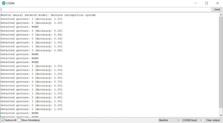
Serial monitor output of Neuton gesture recognition system
And.. that's all!
Schematics, diagrams and documents
Code
Credits

leonardocavagnis
Passionate Embedded System Engineer | IOT and AI Enthusiast | Technical writing addicted


