Flowguard: Real-time Water Management With Iot And Ai
About the project
Empowering Students for a Sustainable Future through Real-time Water Monitoring and Wastage Prevention with TinyML and IoT
Project info
Difficulty: Difficult
Platforms: Arduino, Autodesk, DFRobot, IFTTT, Edge Impulse
Estimated time: 1 day
License: Apache License 2.0 (Apache-2.0)
Items used in this project
Hardware components
Software apps and online services
Story
In a world where sustainable practices have become imperative, water conservation stands out as a pressing concern. With this in mind, we are proud to present FlowGuard, a groundbreaking project designed to revolutionize water usage monitoring and water wastage prevention. By leveraging cutting-edge technology, FlowGuard aims to foster a culture of water conservation, starting from the campus itself.
At its core, FlowGuard offers real-time water usage monitoring, providing administrators with valuable insights into consumption patterns. Equipped with advanced sensors and intelligent algorithms, the system enables administrators to identify potential areas of water wastage and implement targeted strategies for optimization.
However, FlowGuard goes beyond mere monitoring. It acts as a proactive guardian, instantly notifying users and staff when anomalies or excessive water usage are detected. These alerts serve as powerful reminders, encouraging individuals to take immediate action and rectify any wasteful practices.
By exhorting the campus community to actively participate in water conservation efforts, FlowGuard fosters a sense of responsibility and ownership among students, faculty, and staff. With instant notifications serving as gentle reminders, individuals are inspired to make conscious choices and adopt sustainable water practices in their daily lives.
FlowGuard stands as a testament to our commitment to a sustainable future. By promoting real-time monitoring, proactive alerts, and active engagement, this project serves as a catalyst for change. Together, let us embrace FlowGuard and embark on a transformative journey toward a campus where water is valued, conserved, and cherished as a precious resource for generations to come.
Demo Video
Features
- Real-time water usage monitoring with an intuitive dashboard
- Instant sound alert if water wastage detected
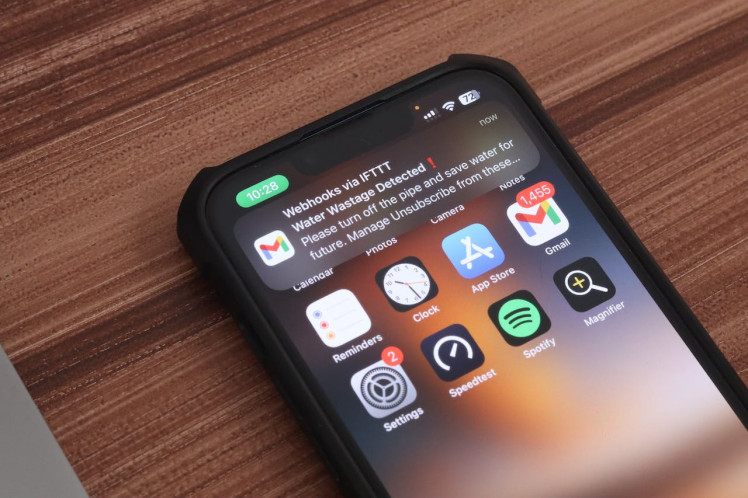
- Instant email alert to admins in case of water wastage
How Does It Work
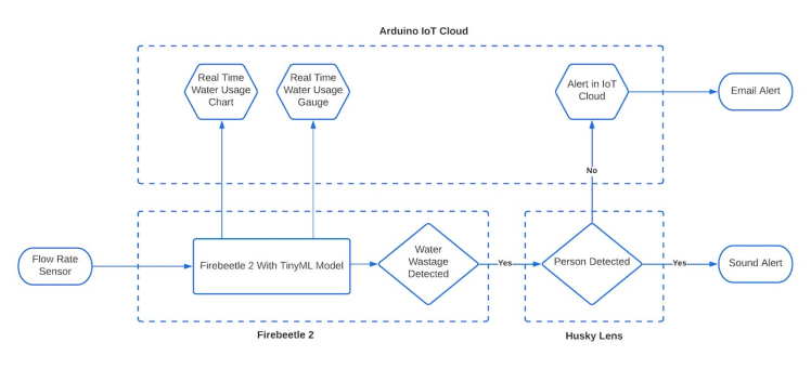
FlowGuard operates by utilizing a water flow sensor that continuously calculates the instantaneous water flow rate. This data is seamlessly transmitted to the FireBeetle microcontroller, enabling a constant flow of information. The real-time flow data serves a dual purpose within the system. Firstly, it is updated in the Arduino IoT cloud, providing users with up-to-date insights into water consumption patterns. Simultaneously, the data is fed into a TinyML model, which analyzes and detects the flow state. If the model identifies normal flow or a sustained high flow rate for 5 minutes, indicating excessive water usage, the system engages the Husky Lens for human presence detection. Upon identifying a person, FlowGuard triggers a sound alert as an immediate notification. Conversely, if no human presence is detected, an alert is generated in the Arduino IoT cloud, instantly notifying administrators via email. Through this integrated approach, FlowGuard ensures prompt action is taken to prevent water wastage, promoting responsible water usage and contributing to a sustainable future.
ESP32 FireBeetle
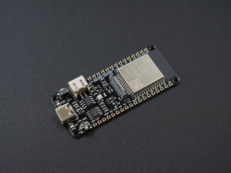
Here we used the esp32 as the brain of our system. The ESP32 FireBeetle is a powerful microcontroller module based on the ESP32 system-on-a-chip (SoC). It offers a wide range of features, making it suitable for this project and some of the key features are
- Dual-core Xtensa LX6 microprocessors
- Clock frequency up to 240 MHz
- Integrated Wi-Fi and Bluetooth connectivity
- Support for multiple communication protocols (SPI, I2C, UART, etc.)
- Rich set of GPIO pins for versatile connectivity
- Support for analog input and PWM output
- Onboard memory and storage options
- Low power consumption and energy-saving features
- Programmable using the Arduino IDE and other development environments
- Support I2S
Gravity HUSKYLENS
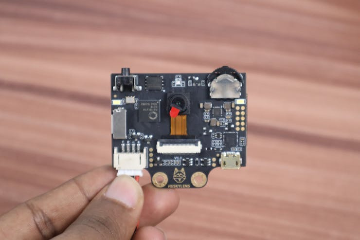
HuskyLens is an intelligent vision sensor module designed for machine vision applications by DF Robot. It combines a camera, image processing algorithms, and artificial intelligence (AI) capabilities into a compact module. The HuskyLens module is capable of recognizing and tracking objects, detecting colours, gestures, and shapes, and performing various visual tasks in real-time.
In this project, we used the Husky lens to detect the person in front of the pipe. In order to do that we moved on to the object recognition menu and trained the husky lens to detect the persons.
If a person is detected, the Husky lens will return the ID 1, otherwise, it will return another number.

There are two options for communicating with this module either via the I2C or UART. In our system we used I2C and through the settings option, users can easily configure the module to communicate using UART instead of I2C if it better suits their project requirements.
Flow Rate Sensor
The sensor's purpose is to accurately measure the flow rate of a liquid as it passes through. It achieves this by utilizing a magnetic rotor and a hall effect sensor. As the liquid flows through the sensor, its movement causes the magnetic rotor to rotate. The speed of the rotor's rotation is directly proportional to the flow rate of the liquid. Positioned in proximity to the rotor, the hall effect sensor detects this rotation and generates a pulse width signal. By analyzing the pulse width signal, the flow rate of the liquid can be calculated precisely. This combination of the magnetic rotor and hall effect sensor enables precise measurement of liquid flow rates.
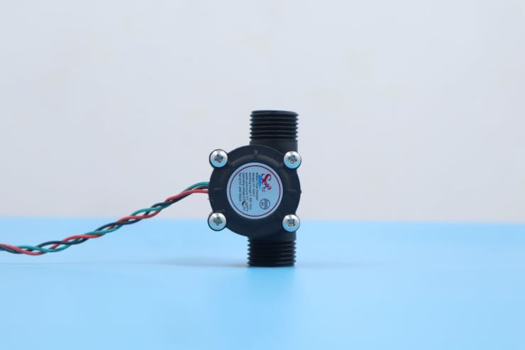
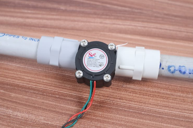
This is the flow rate sensor connected between the two pipes in the water flow.
Audio
These are the possible ways to generate audio on the ESP32 FireBeetle board.
Built-in DAC (Digital-to-Analog Converter): The ESP32 FireBeetle board includes a built-in DAC, which allows you to convert digital audio data into analog signals. You can use the DAC to produce simple waveforms or play back pre-recorded audio samples. By controlling the voltage output of the DAC, you can generate different audio frequencies and modulate them to create sound.
- Built-in DAC (Digital-to-Analog Converter): The ESP32 FireBeetle board includes a built-in DAC, which allows you to convert digital audio data into analog signals. You can use the DAC to produce simple waveforms or play back pre-recorded audio samples. By controlling the voltage output of the DAC, you can generate different audio frequencies and modulate them to create sound.
- I2S (Inter-IC Sound) Interface: The ESP32 FireBeetle also supports the I2S interface, commonly used for audio data transmission. The I2S interface lets you connect external audio codecs, digital-to-analog converters (DACs), or amplifiers to generate high-quality audio. You can utilize the I2S interface to stream audio data from memory or input audio from external devices such as microphones
- PWM (Pulse Width Modulation): The ESP32 FireBeetle board provides PWM functionality, which can be used to produce audio signals. By modulating the duty cycle of a PWM signal at a specific frequency, you can generate different audio tones. While PWM audio might not be as high-fidelity as DAC or I2S, it can still be suitable for basic audio applications.
- External Audio Modules: If the built-in audio capabilities of the ESP32 FireBeetle are insufficient for your requirements, you can consider using external audio modules or shields. There are various audio-specific modules available, such as MP3 decoders, audio amplifiers, and audio playback modules. These modules can be connected to the ESP32 FireBeetle via interfaces like I2C, SPI, or UART to enhance the audio capabilities of your project.
In this project, we used the I2S (Inter-IC Sound) Interface.
While the I2S interface itself is not considered a recent development, it has stood the test of time and remains widely used today. It's popularity and widespread adoption in the audio industry have solidified its position as a standard interface for high-quality audio data transfer. You can read more about the I2S protocol here.
Actually, the ESP32 has two I2S peripherals, I2S0, and I2S1. Each one can be configured as a Controller or Target, and each one can be an audio Transmitter or Receiver.
We cannot play I2S output directly on a speaker from the ESP32 microcontroller without additional components. The I2S (Inter-IC Sound) interface is a digital audio communication protocol used for transmitting audio data between integrated circuits, but it does not provide sufficient power to drive a speaker.
To play audio through a speaker using the ESP32's I2S interface, we need an audio amplifier circuit. An audio amplifier is necessary to increase the power of the audio signal to a level that can drive a speaker effectively. The amplified audio signal from the I2S interface is typically connected to the audio input of the amplifier, which then drives the speaker.
The MAX98357A I2S amplifier module is a common choice for this purpose. It combines the I2S interface with a built-in audio amplifier, allowing you to connect the module directly to a speaker. The module amplifies the I2S audio signal and provides sufficient power to drive the speaker.
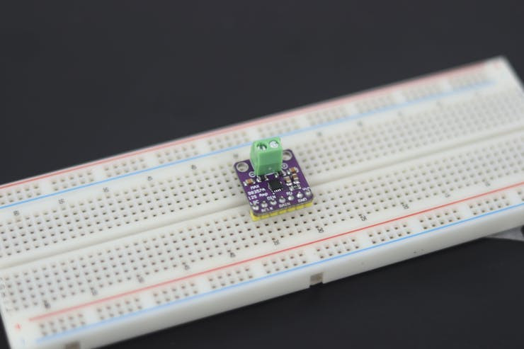
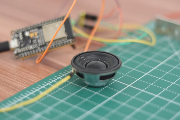
The device can output up to 3 watts into a 4-ohm load. So to match the impedance we used a 4ohm 3-watt speaker.
We used a Google TTS to convert the text given in the code as the audio output to the speaker.
Enclosure
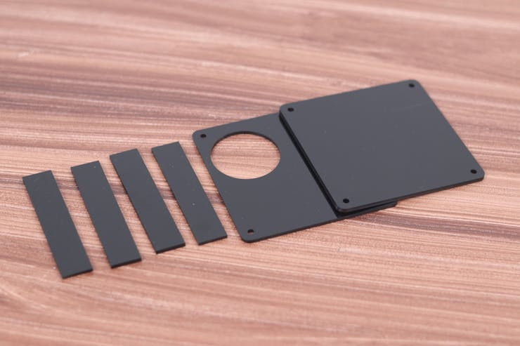
In this project, we opted to use a 3mm black acrylic sheet as the enclosure for our device. To obtain the desired shape, we collaborated with a local store equipped with laser-cutting capabilities. We provided them with a DXF file, which contains the design specifications for the enclosure. The laser cutter precisely followed the instructions in the DXF file to cut the black acrylic sheet, resulting in a custom enclosure for our project. The choice of black acrylic sheet adds a sleek and professional look to the device while providing durability and protection for the internal components.
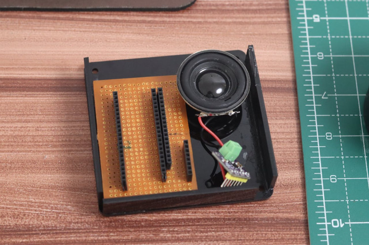
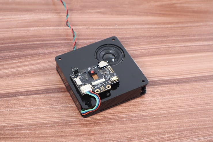
This is our final device after finishing the assembly.
TinyML Model Training With Edge Impulse
In our project, we have incorporated a water flow sensor that generates a pulse width modulation (PWM) signal as its primary output. Instead of directly capturing the analog values from the sensor, we have opted for a method where the flow rate is computed using an equation that takes into account the PWM signal. By employing this approach, we are able to derive precise flow rate measurements. These measurements are recorded as time series data, enabling us to observe and monitor fluctuations in the flow rate over a period of time.
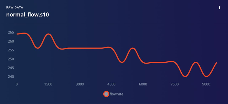
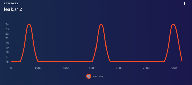
To facilitate our analysis, we have gathered flow rate data for three distinct scenarios: no flow, normal flow, and a leak. During our investigation, we successfully identified distinguishable patterns within the flow rate data associated with each scenario. These patterns exhibit characteristic features that our model can effectively detect, allowing for an accurate classification of the prevailing flow conditions.
To collect data for your project, follow these steps:
- Upload dataCollection.ino to FireBeetle.
- Plug your FireBeetle into the computer.
- Run SerialDataCollection.py in the terminal.
- Enter 's' in the terminal to start recording.
- When you have enough data, enter 's' again to stop recording.
- Once you have stopped recording, it will generate a CSV file on your computer. Name it according to the flow state.
- Upload the CSV file to EdgeImpulse using the Data Acquisition Tab.
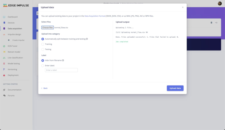
Once we uploaded the CSV files containing our flow rate data to Edge Impulse, we proceeded to partition the entire dataset into smaller samples, each spanning a duration of 6 seconds. This operation, commonly referred to as data splitting, serves the purpose of breaking down the data into manageable segments, enabling us to conduct in-depth analysis and perform the necessary manipulations required for model development.
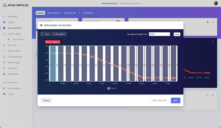
Through the process of breaking down the data into smaller chunks, we enhance our ability to discern significant trends and patterns that hold relevance for our model. This approach offers the advantage of effectively utilising the data for both training and testing purposes. By dividing the data into these manageable samples, we gain greater control over the input and output for each specific segment, thereby streamlining the training and evaluation process.
To provide a visual representation, we have chosen to visualise a representative sample from each class that was collected. These visualizations offer a concise overview of the data for each specific category, encapsulating the distinctive characteristics and features associated with each class. By examining these visualizations, we can gain insights into the unique traits of each flow rate scenario and utilize them in our model development and analysis.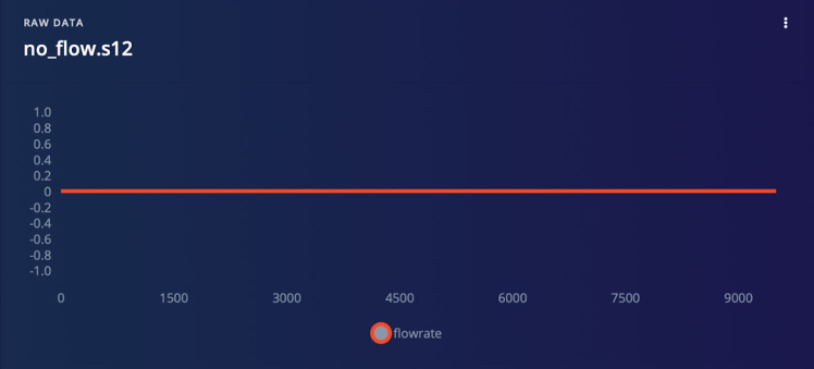
Following the aforementioned process of segmenting our flow rate data into smaller samples, we proceeded to perform an additional division of the dataset. This division resulted in the formation of two distinct subsets: a training dataset and a testing dataset. This pivotal step in the model creation process is commonly referred to as data partitioning. Data partitioning is a crucial aspect of model development as it ensures the availability of separate datasets for training and testing purposes. By allocating a specific portion of the data to the training dataset, we facilitate the model's learning process and enable it to discern underlying patterns and relationships within the data. On the other hand, the testing dataset serves as an independent evaluation set, allowing us to assess the model's performance on unseen data and gauge its generalization capabilities.
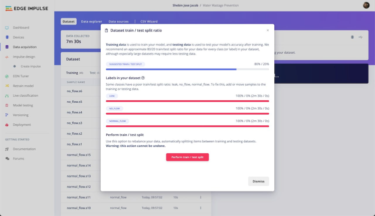
Utilizing a clean and well-organized dataset for training instils confidence in the quality of data our model learns from. This meticulous approach ensures that our model is exposed to high-quality information, enabling it to grasp the underlying intricacies and nuances of the flow rate patterns. As a result, we can expect our model to produce reliable and precise results when confronted with new, unseen data. The distinct separation of data into training and testing subsets serves as a safeguard against overfitting, a common challenge in machine learning. By evaluating the model's performance on an independent testing dataset, we gain insights into its generalization capabilities, ensuring that it can effectively generalize and make accurate predictions beyond the training dataset.
2. Impulse Design
An impulse represents a specialized machine learning pipeline engineered to derive valuable insights from raw data and leverage them for predictive purposes or classification of novel data. Constructing an impulse typically entails three fundamental stages: signal processing, feature extraction, and learning.
During the initial stage of signal processing, the raw data undergoes a series of operations to cleanse and organize it into a format more amenable to analysis. This may encompass the elimination of noise or superfluous information, as well as preprocessing steps to enhance the usefulness of the data for subsequent stages.
Following signal processing, the feature extraction stage ensues, wherein significant attributes or patterns are identified and extracted from the processed data. These features constitute pivotal pieces of information that the subsequent learning block will employ for classifying or predicting new data.
Finally, the learning block assumes responsibility for the classification or prediction of new data based on the features extracted in the previous stage. This may involve training a machine learning model utilizing the extracted features or employing alternative classification or prediction algorithms to accomplish the task at hand.
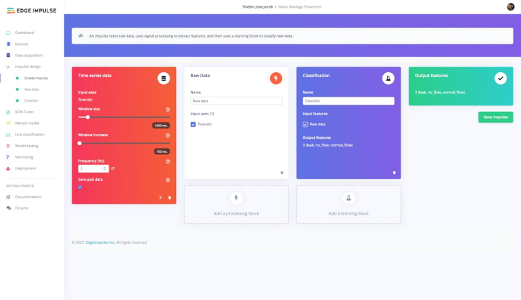
In our project, machine learning plays a pivotal role in the classification of liquid flow into three distinct classes. To achieve this objective, we employ Time Series Data as the input block within the impulse. This type of data encompasses a sequence of measurements captured at regular intervals over a specific time span, making it particularly suitable for analyzing flow rate data and uncovering meaningful trends and patterns.
For the processing block, we utilize Raw Data, which denotes the unprocessed data acquired directly from the flow sensor. Subsequently, this raw data is channelled through the processing block, where it undergoes a series of cleaning and organization steps to enhance its suitability for analysis.
In the final phase, we employ a Classifier block as the learning block. This specific algorithmic approach is designed to assign data to predefined categories and is highly suited for the task of classifying flow rate data into three distinct categories. By leveraging classification within the learning block, we effectively categorize the flow rate data into one of the following classes: no flow, normal flow, or a leak.
At this stage of the process, we are ready to proceed to the Raw Data tab, where we can commence the generation of features. The Raw Data tab provides various options for manipulating the data, such as adjusting axis scales or applying filters. In our particular case, we have opted to retain the default settings and progress directly to the feature generation phase.
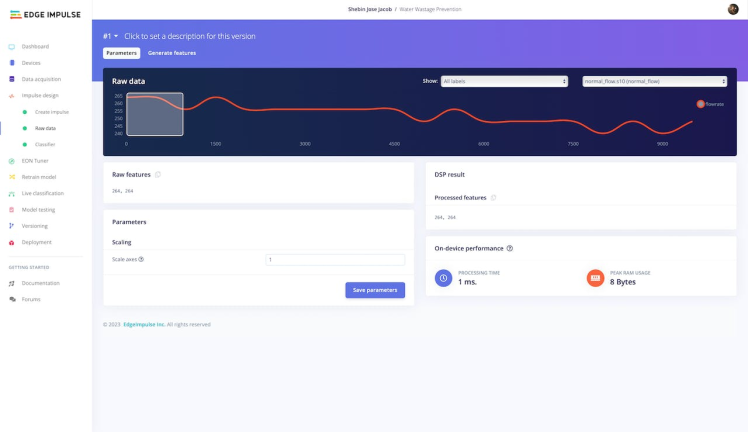
The generation of features involves the application of diverse algorithms and techniques to detect significant patterns and characteristics within the flow rate data. These extracted features serve as crucial inputs for the learning block of our impulse, enabling it to classify the flow rate data into one of the three predefined categories. Through meticulous selection and extraction of relevant features, we aim to develop a classification model that is both highly accurate and reliable in its ability to categorize flow rate data. By leveraging various algorithms and techniques tailored for feature generation, we can uncover meaningful insights and distinctive attributes present in the data. These features act as informative representations that capture essential patterns and characteristics intrinsic to the flow rate measurements. By ensuring the inclusion of relevant and discriminative features, we enhance the model's capability to accurately distinguish between the different flow rate categories.
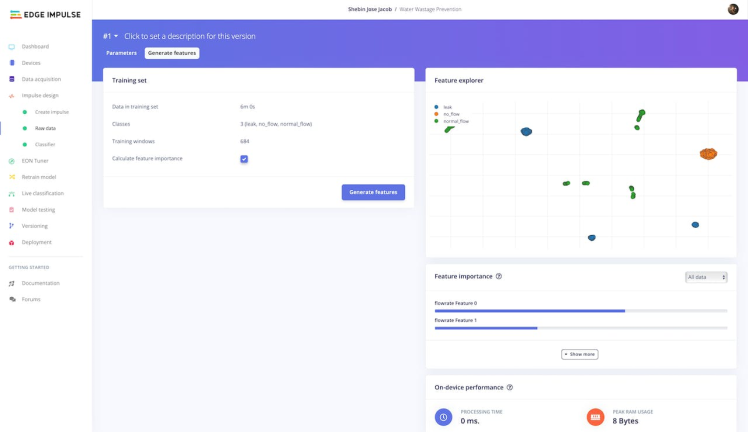
Upon analyzing the features, we have ascertained that they exhibit distinct separation, with no overlap observed between the classes. This promising observation indicates the presence of a high-quality dataset that is highly suitable for model generation.
3. Model Training
Having successfully extracted and prepared our features, we now transition to the Classifier tab for training our model. This tab offers various options for modifying the model's behavior, encompassing parameters such as the number of neurons in the hidden layer, the learning rate, and the number of epochs.
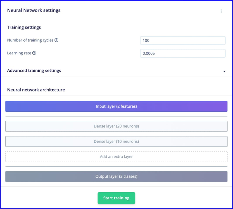
Through an iterative process of trial and error, we conducted experiments with different parameter combinations to attain a training accuracy that aligns with our predefined standards. This process entailed fine-tuning factors such as the number of neurons in the hidden layer, the learning rate, and the number of epochs, among other considerations. Ultimately, we were able to identify an optimal set of parameters that yielded a model exhibiting the desired training accuracy, as depicted in the accompanying figure.
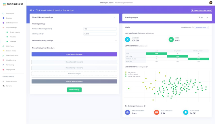
The achieved level of accuracy is remarkably high, signifying the model's exceptional capability in accurately classifying flow rate data into the designated three categories. Moreover, the low loss value indicates that our model generates predictions with a profound sense of confidence, bolstering the overall reliability and credibility of our results.
4. Model Testing
After successfully training and fine-tuning our model to achieve a commendable level of accuracy, the time has come to assess its performance on unseen data. To accomplish this, we will proceed to the Model Testing tab, where we will employ the Classify All feature to comprehensively evaluate the model's capabilities.
By subjecting the model to a fresh set of data, we aim to determine its proficiency in accurately predicting flow rate patterns and effectively classifying the data into the three designated categories. A strong performance on this test data will instil confidence in the model's ability to provide valuable and reliable insights when deployed in real-world scenarios.
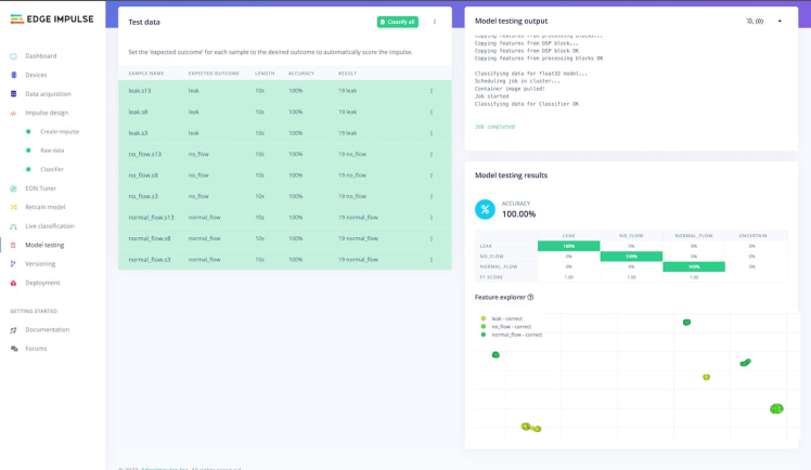
Following the execution of the test, we observed exceptional performance of our model. It demonstrated a remarkable accuracy in accurately classifying the flow rate data into the designated three categories. This outcome serves as a robust validation of the model's efficacy and affirms its capacity.
5. Deployment
With the successful development and testing of our efficient flow rate prediction and classification model, we are now prepared to proceed with its deployment as an Arduino Library.
To initiate the deployment of our model as an Arduino Library, we will navigate to the Deployment tab and follow the provided instructions to construct the library.
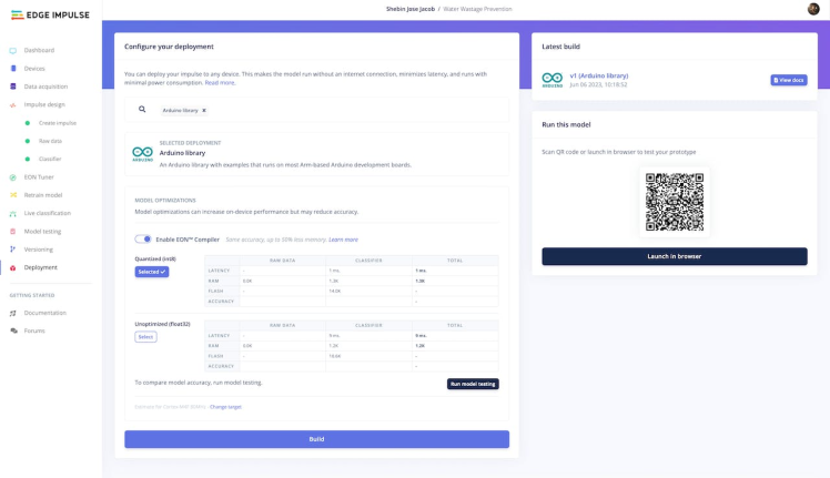
During the library-building process, we are presented with the opportunity to activate optimizations through the EON Compiler. This feature enables us to enhance the model's performance by optimizing the code to ensure efficient execution on the device. Although this step is optional, it proves advantageous in accelerating the speed and efficiency of our model, especially when deploying it in resource-limited environments.
Once the process of constructing the Arduino library for our model is finalized, we will receive a zip file encompassing the model and a collection of illustrative examples showcasing its utilization in diverse contexts. Integrating the library into the Arduino Integrated Development Environment (IDE) is a straightforward procedure. By navigating to Sketch > Include Library > Add.ZIP Library within the IDE, we can select the.zip file generated during the build process. This simple action will install the library, making it readily accessible for implementation within our projects.
Real-Time Monitoring With Arduino IoT Cloud
It is time to construct a dashboard for real-time monitoring of water usage and to accomplish this, we are harnessing the capabilities of Arduino IoT Cloud. Arduino IoT Cloud provides a powerful platform that enables us to seamlessly connect our devices to the cloud, facilitating efficient data collection and analysis. With the integration of Arduino IoT Cloud, we can effortlessly capture and transmit water usage data from our sensors in real time. This data can then be visualized and monitored through a user-friendly dashboard, allowing us to gain valuable insights into water consumption patterns and make informed decisions for efficient resource management. Arduino IoT Cloud empowers us to create a comprehensive and interactive monitoring system that enhances our ability to track, analyze, and optimize water usage, contributing to a more sustainable and environmentally conscious approach.
Setting Up Arduino IoT CloudAnd Building Dashboard
Here we have an official guide by Arduino that outlines the process of setting up Arduino IoT Cloud. By following this guide, you will be able to establish a connection between your FireBeetle 2 device and the IoT Cloud platform. By successfully completing the steps outlined in the guide, you will have a fully functional dashboard that is connected to your FireBeetle 2 device, empowering you to efficiently monitor and control its operations.
Intuitive Dashboard
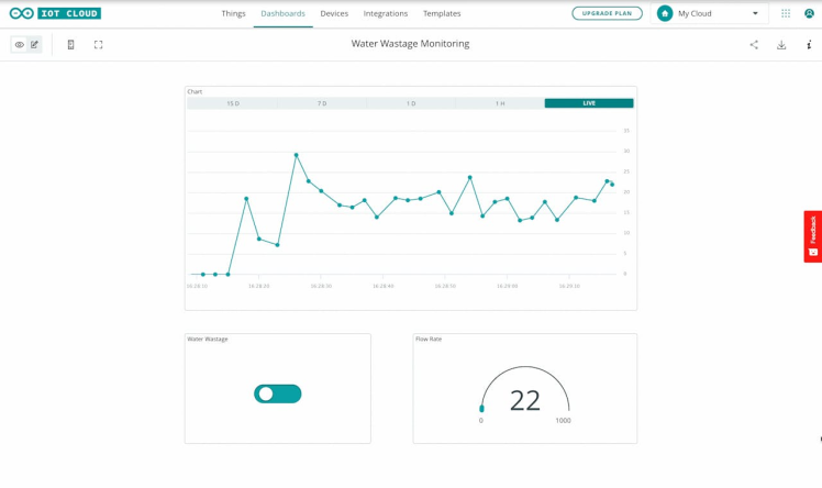
By diligently following the provided guide, we have successfully constructed a comprehensive dashboard comprising three key widgets. The first widget is a chart widget that vividly visualizes the water usage data, enabling us to track and analyze consumption patterns over time. The second widget is a button that serves as an indicator, clearly displaying whether water is being wasted or not, providing valuable insights for conservation efforts. Lastly, we have integrated a gauge widget into the dashboard, which dynamically represents the real-time water usage rate, allowing for instant monitoring and awareness of consumption levels. These widgets collectively provide us with a holistic view of water usage, empowering us to make informed decisions and take proactive measures towards efficient resource management.
Integrating IFTTT With Arduino IoT Cloud
In our project, we have seamlessly integrated IFTTT (If This Then That) with the Arduino IoT cloud, enabling powerful automation and alerting capabilities. Specifically, we have harnessed the potential of IFTTT by connecting it to our Water Wastage button. This integration ensures that whenever water wastage is detected, the system triggers an email alert. By leveraging IFTTT's versatile platform, we can effortlessly enhance the effectiveness of our water wastage prevention system, promptly notifying users and enabling swift action to be taken. This guide serves as an invaluable resource, shedding light on the seamless process of integrating IFTTT with the Arduino IoT cloud, further solidifying the reliability and efficiency of our water conservation project.
Assets For Replication
Within this GitHub repository, you will discover all the assets necessary for replication — a comprehensive collection that encompasses code, designs, and resources. In addition, you can access our publicly available Edge Impulse project. Feel free to immerse yourself in its capabilities, conducting experiments and discovering novel solutions. Together, let us build a more sustainable world!
Code:https://github.com/CodersCafeTech/Water-Wastage-Prevention-With-TinyML
Edge Impulse Project:https://studio.edgeimpulse.com/public/235883/latest


Leave your feedback...