Flashing Led Christmas Ball Using Pcb
About the project
Simple Christmas ball ornament using pcb
Project info
Difficulty: Easy
Platforms: JLCPCB
Estimated time: 3 hours
License: Creative Commons Attribution CC BY version 4.0 or later (CC BY 4+)
Items used in this project
Story

Hello there,
The Christmas season is here. As an electronics enthusiast, I planned to make something different this time. After some lazy thinking, I decided to build an electronic Christmas ball ornament. the plan is to build a round-shaped PCB with blinking LEDs. It uses only a few components so anyone can build this beautiful ornament. we can decorate Christmas trees, homes etc with this. now let's see how I made this. let's get started.
CIRCUIT DIAGRAM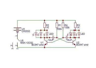
Let's start with the circuit. we need a simple astable multivibrator circuit to blink the LEDs here I am using two transistors for that. I added 6 LEDs for the blinking sequence. In easyeda, I designed the circuit. The main component is the S8050 transistor. Above you can see the completed circuit diagram.
PCB DESIGNING1 / 2

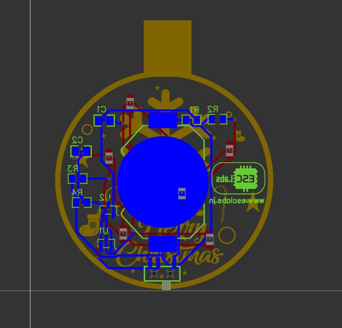
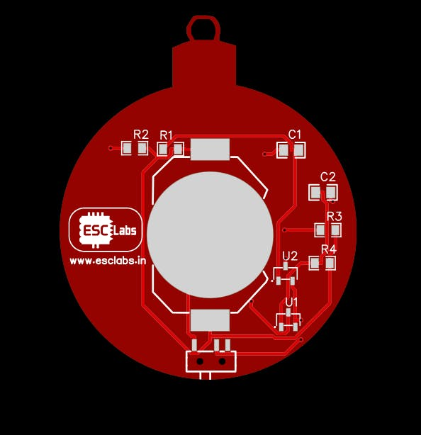
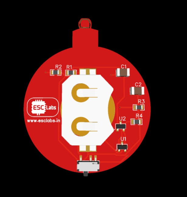
After designing the circuit. I converted the circuit into a PCB and I outlined the PCB just like a Christmas ball. I added a hole to tie the string and also I added some Christmas icons. After the design, our PCB looked like this: then I downloaded the Gerber files for the PCB fabrication.
1 / 4


PCB FABRICATIONFROM JLCPCB
1 / 3

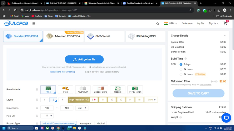
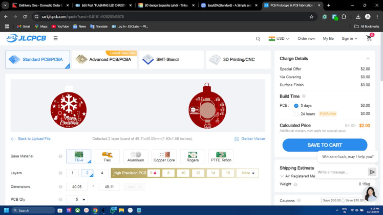
For PCB fabrication I went to JLCPCB.com. I always prefer jlcpcb for PCB manufacturing because there Quality and low pricing. You can get 5 PCBs for just 2$ also their other services like assembly, and 3D printing are also very cheap. To order our PCBs just click. on order now. Select the gerber file. After uploading the Gerber file we can select quantity, colour, thickness etc. After that, we can select the shipping method and address. Then we can place the order.
1 / 2
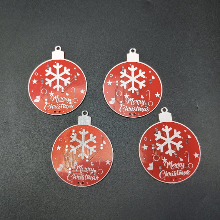
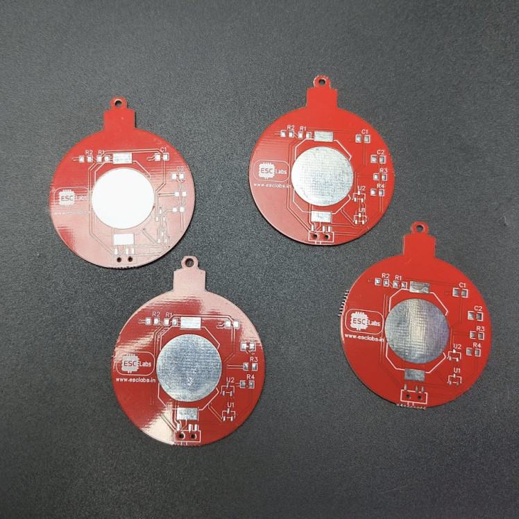
After two weeks I received the pack from JLCPCB. You can see the PCBs are very good in quality as always.
COMPONENTS NEEDED- SOT23 S8050 Transistor*2
- 0805 SMD RESISTOR-100K*2
- 0805 SMD RESISTOR-470ohm*2
- 0805 SMD CAPACITOR-10uF*2
- SMD SWITCH*1
- 3V coin cell holder*1
- 3V coin cell Battery*1
- CUSTOM PCB FROM JLCPCB*1
1 / 2
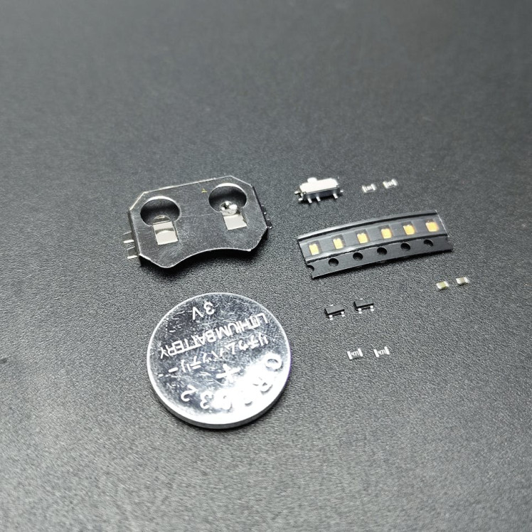
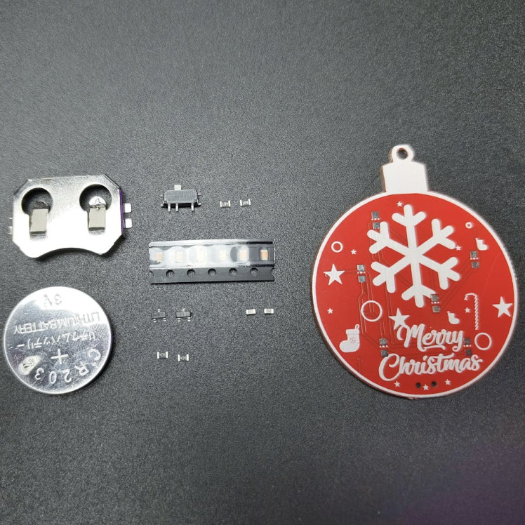
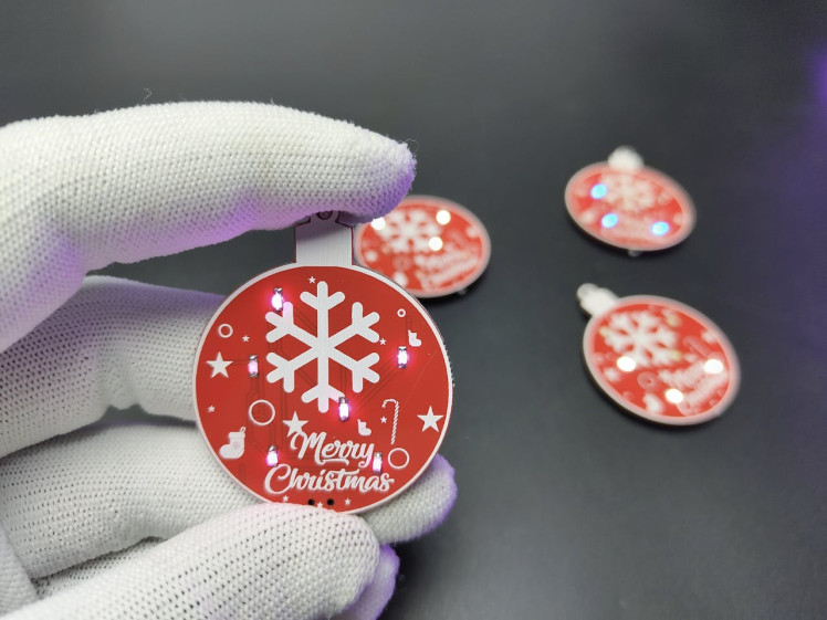
Now let's grab all the components. Then we can simply solder to the PCB you can either solder the components using a soldering iron or we can use the reflow method. I tried both and both are very easy. Here is the assembled PCB and you can see the working. I have also assembled a couple of other PCBs with different coloured LEDs. So you can see the beautiful working of these PCBs.
1 / 2

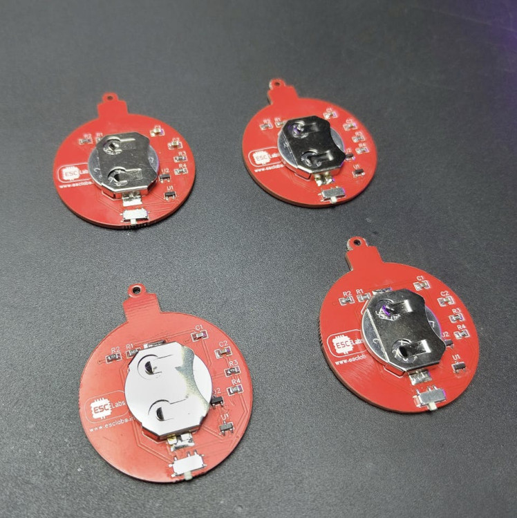
You can download the circuit diagram and Gerber file from here. I wish a happy Christmas holiday to all. So that's all about for today. Hope you enjoyed and learned something new from this article. Thanks
1 / 2






Leave your feedback...