

Esp32-s3 Powerfeather Demonstrations

Made by PowerFeather / Sustainability / IoT
About the project
Exploring the ESP32-S3 PowerFeather's power management and monitoring features
Project info
Items used in this project
Hardware components

Hand tools and fabrication machines
Story
Introduction
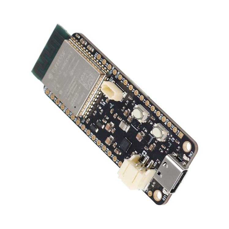
First things first: what is the ESP32-S3 PowerFeather? Simply put, it's a low-power, Feather-format ESP32 dev board for LiPo/Li-Ion and solar powered projects. Its extensive power management and monitoring features sets it apart from other similar boards, thanks to the on-board Texas Instruments BQ25628E battery charger IC and Onsemi LC709204F battery fuel gauge. To see how it compares against something like the FireBeetle 2 (plus some other hardware), take a look at this comparison spreadsheet.
To assist users in using the power management and monitoring features, an open-source Arduino/ESP-IDF library called PowerFeather-SDK is provided.
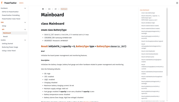 PowerFeather-SDK API
This project is more exploratory, rather than building a thing. We'll be conducting various demonstrations to try out the various power management and monitoring features of the ESP32-S3 PowerFeather.
Setup
The demo app we'll use to explore the power management and monitoring features is based on Arduino and uses PowerFeather-SDK. So, follow these instructions to add support for the ESP32-S3 PowerFeather in the Arduino IDE and install the PowerFeather-SDK library.
Once done, you can download the demo app source code as a ZIP file on GitHub. Extract the ZIP file and open the project in Arduino IDE.
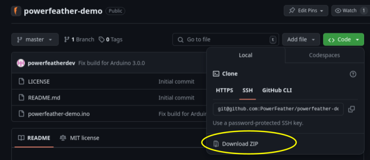
Demo source code as a ZIP file from GitHub
Afterwards, install the additional libraries needed by the demo app: ESPAsyncWebServer and ESPUI.
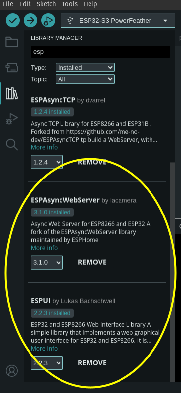
Additional demo dependencies
Don't forget to set the target board to "ESP32-S3 PowerFeather". You should now be able to build the demo app and flash it onto your ESP32-S3 PowerFeather like any other Arduino sketch.
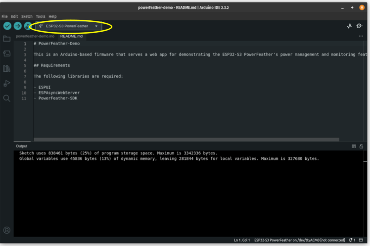
Building the ESP32-S3 PowerFeather demo with Arduino
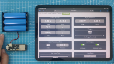
Once the demo app is up and running on the ESP32-S3 PowerFeather, it acts as an access point and serves the demo web app. A phone, tablet or computer can connect to this access point, and the demo app can then be loaded by a web browser at the IP address 192.168.1.1.
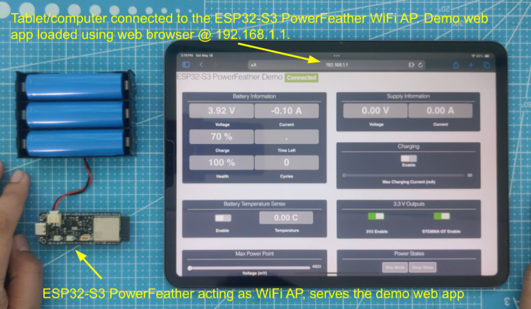 Tablet connected to ESP32-S3 PowerFeather AP, loaded demo app on browser
The demo web app is a dashboard displaying information and controls of some power-related parameters of the ESP32-S3 PowerFeather:
> Battery Information
- Voltage
- Charge/Discharge Current
- Charge Percent
- Time Left Estimate (time-to-full/time-to-empty)
- Health Percent Estimate
- Cycles Estimate
> Supply Information
- Voltage
- Current
> Battery Temperature Sense
- Enable Battery Temperature Sense
- Battery Temperature Display
> Charging
- Enable/Disable Charging
- Max Charging Current (from 50 mA to 2000 mA)
> 3.3 V Outputs
- Enable/Disable 3.3 V Header Pin Output
- Enable/Disable STEMMA QT 3.3V Output
> Max Power Point
- Set Max Power Point Voltage (from 4600 mV to 16800 mV)
> Power States
- Enter Ship Mode
- Enter Deep Sleep
With the demo app flashed on the ESP32-S3 PowerFeather, we can now perform the demonstrations.
Demonstrations
# 1 Power Inputs
The ESP32-S3 PowerFeather has three power inputs:
a. Battery: up to 4.2 V, 2 A via JST PH connector
b. USB: up to 5 V, 2 A via USB-C connector
c. External DC: up to 18 V, 2 A via the VDC header pin
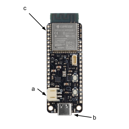
ESP32-S3 PowerFeather power inputs
With just the battery connected, the dashboard shows -0.1 A battery current. The negative value means that it's discharging. Since no USB or external DC power source is connected, the supply information displays 0 V and 0 A.
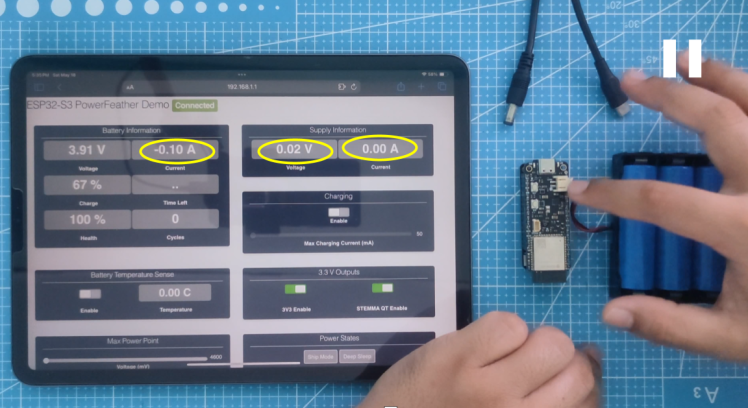 Only the battery connected
Connecting USB power, the supply voltage and current now displays around 5 V and 0.08 A. The battery current drops to 0 A, indicating it's neither charging or discharging.
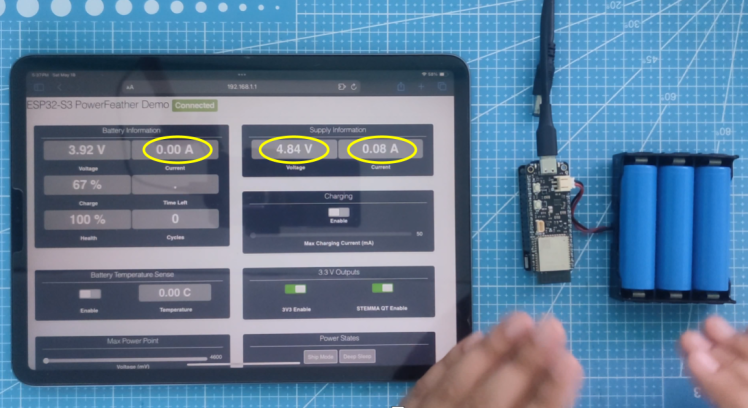 USB power + battery connected
Connecting an external DC source (through a ProtoWing barrel VDC pin breakout in the photo below) supersedes the still connected USB power and it's now used as the supply, reflected by the approximately 18 V and 0.02 A in the supply information.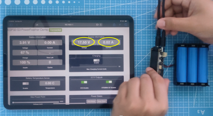 18 V external DC source + USB power + battery connected
It's ok to have all these three sources connected at the same time. The board juggles between them appropriately to prevent brownout reset when connecting/disconnecting power sources, as long as one of the sources is connected at any point in time.
# 2 Ship Mode and Deep Sleep Current
A Nordic Power Profiler Kit II acts as the battery that powers the board while measuring its power consumption.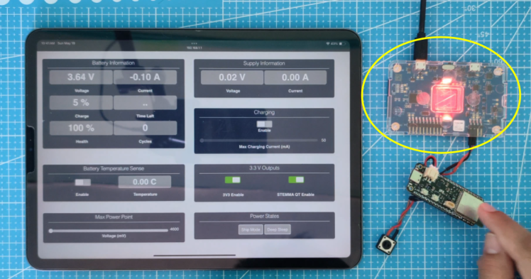 Nordic Power Profiler Kit II acting as battery
The ESP32-S3 module can be put into deep sleep to save power using the Power States -> Deep Sleep button on the dashboard. Typically, current consumed for the entire board when the ESP32-S3 is in deep sleep is less than 20 uA: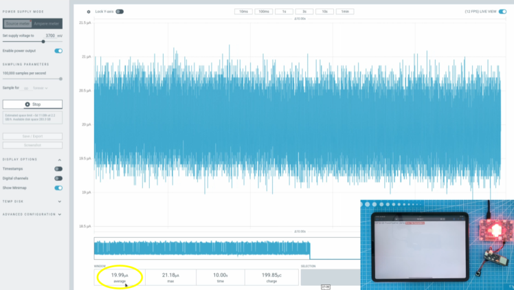 Deep sleep current consumption
Ship mode is a power state where the battery is electronically disconnected, even if it is physically connected. As a result, current consumption in this power state is very low, under 2 uA typically. It can be entered into using the Power State -> Ship Mode button on the dashboard.
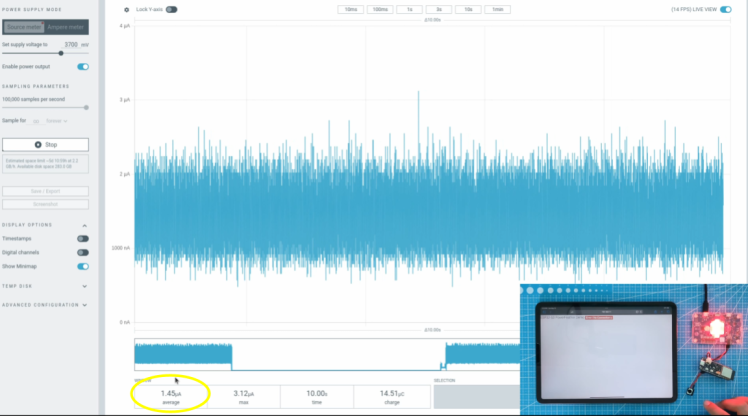 Ship mode current consumption
#3 Enable/Disable 3.3 V Outputs
The board's two 3.3 V outputs (3.3 V header pin output & STEMMA QT 3.3 V output) can be enabled/disabled independently for power saving.
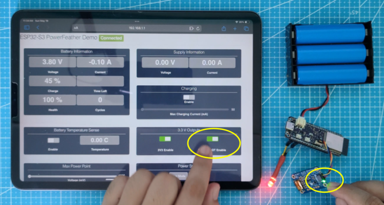
In the photos below, the red LED is powered from the header pin 3.3 V output, and the STEMMA QT module from the STEMMA QT 3.3 V output. Switching on/off the controls on the dashboard, these two devices turn on/off accordingly: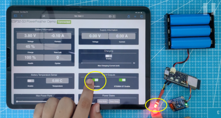 Header pin 3.3 V output enabled, red LED on
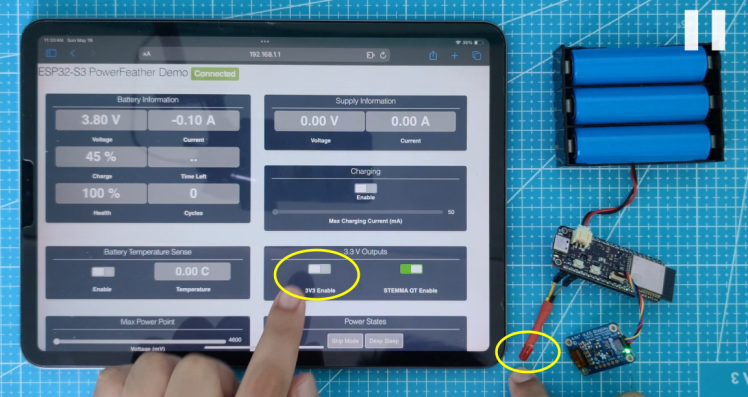 Header pin 3.3 V output disabled, red LED off
 STEMMA QT 3.3 V output disabled, green LED on STEMMA QT module on
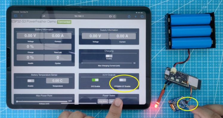
STEMMA QT 3.3 V output disabled, green LED on STEMMA QT module off
#4 Charging Controls
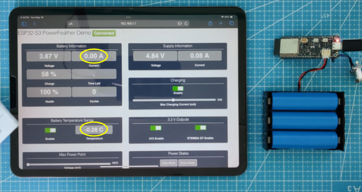
Charging can be enabled or disabled on-demand. When charging is enabled, the red CHG status LED lights up, and the charging current can be measured.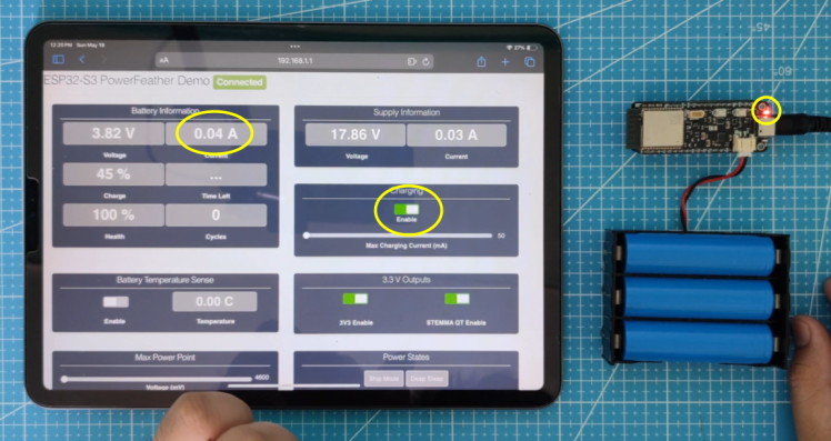 Charging enabled, red CHG LED lights up, battery current is positive, non-zero value
Having the ability to disable charging is useful when you want to charge the battery less than full capacity to extend its lifespan. For example, you can check if the battery is already more than 80 % charged, and your firmware can disable charging if so.
The max charging current can also be set from firmware, from 50 mA to 2000 mA. The charger IC will make sure that the charging current never goes too much above this value during the constant-current phase of the charging cycle.
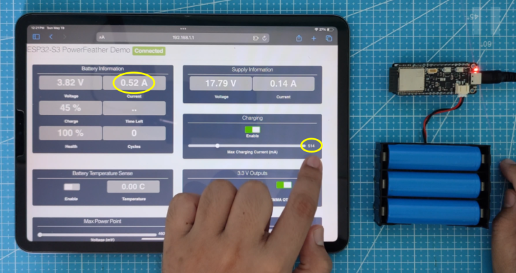 Max charging current set to 514 mA, charging current ~0.52 A
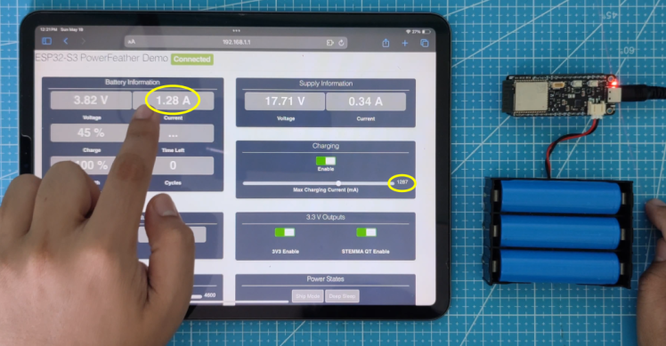 Max charging current set to 1287 mA, charging current ~1.28 A
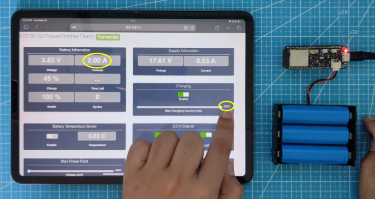 Max charging current set to the maximum supported (2000 mA), charging current is ~2 A
This is useful since the recommended safe charging current is usually related to the battery capacity - usually at 1C. This means that for a 500 mAh battery, it is recommended to not exceed 500 mA of charging current; for a 1000 mAh, 1000 mA of charging current max is recommended, so on and so forth.
#5 Battery Temperature Sensing
A thermistor can be connected to the ESP32-S3 PowerFeather. This enables the charger IC to give a readout of the battery temperature, and to reduce or cut-off charging current when certain temperatures are hit.
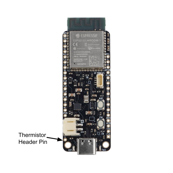
Thermistor header pin location
The graph below shows the relationship between the max charging current % and the temperature.
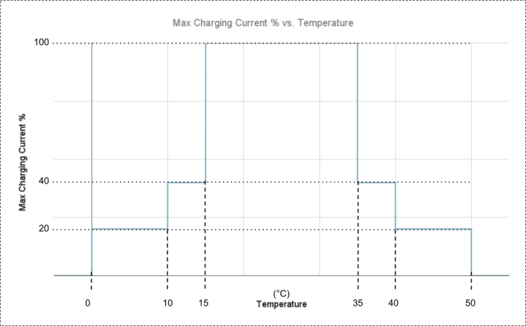 Max charging current % and temperature relationship
If the user sets max charging current to 1000 mA for example, the charger IC is only able to allow charging to go that high if the battery temperature is within 15 C and 35 C. Outside of this temperature range, the max charging current is capped at a certain percentage, illustrated in the table below: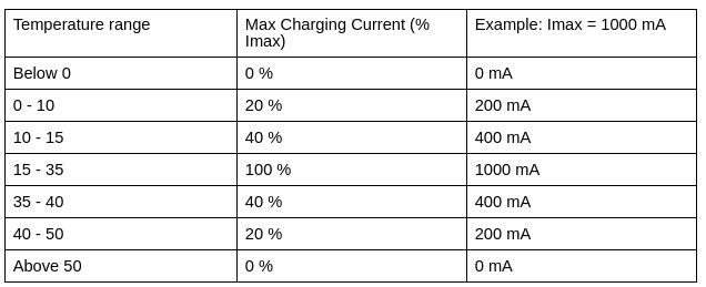
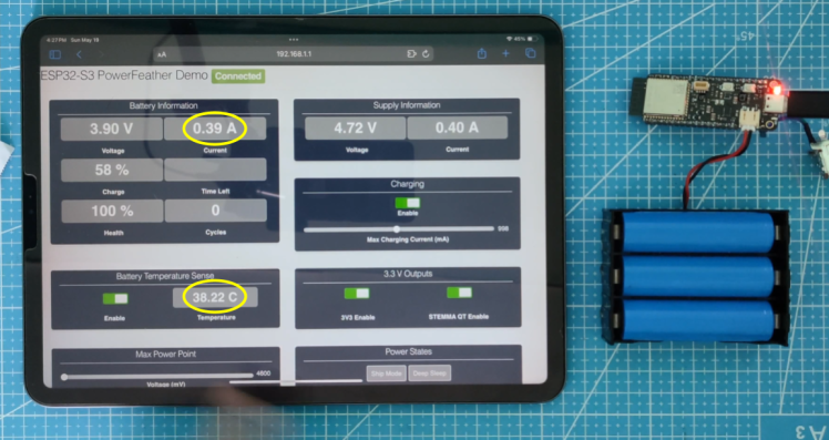
The following pictures show this in action (potentiometer is used instead to simulate a thermistor):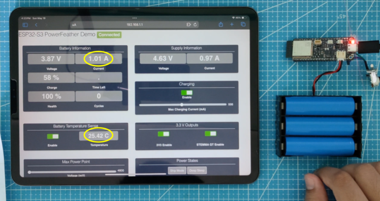 Charging current from 15 C - 35 C: ~ 1 A
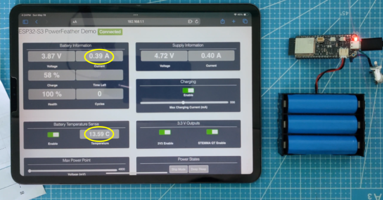 Charging current from 10 C - 15 C: ~ 400 mA
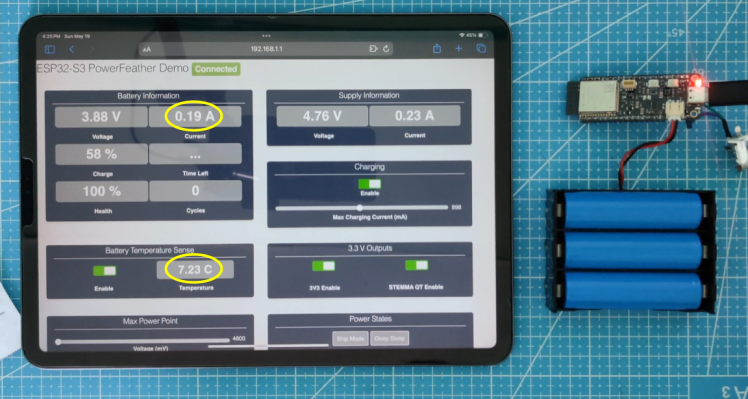 Charging current from 0 C - 10 C: ~ 200 mA
 No charging current below 0 C
 Charging current from 35 C - 40 C: ~ 400 mA
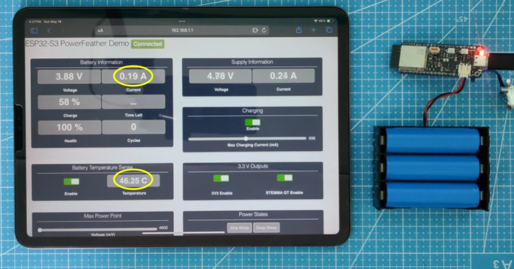 Charging current from 40 C - 50 C: ~ 200 mA
 No charging current above 50 C
#6 Setting MPP Voltage
A solar panel can be connected to the external DC power input (VDC pin). In the photo below, a PowerFeather Protowing is used to break the VDC pin out into a barrel connector, to which the solar panel is connected.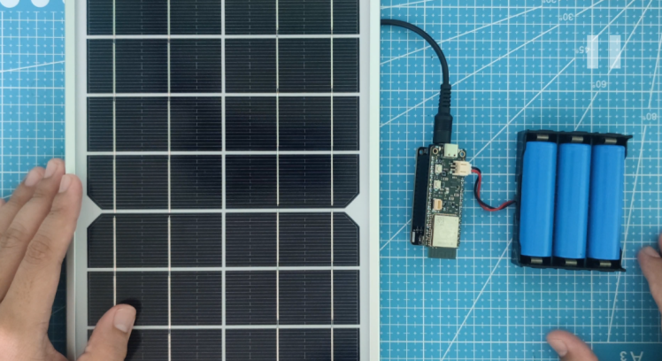 Solar panel and battery connected to ESP32-S3 PowerFeather
The MPP voltage can be set from 4.6 V to 16.8 V to extract power from a solar panel more efficiently. Start with the figure mentioned in the solar panel, then experiment a little bit - set it a little higher or lower than this value.
The photos below illustrate the effect of not setting MPP voltage near panel rated MPP voltage, vs. setting it:
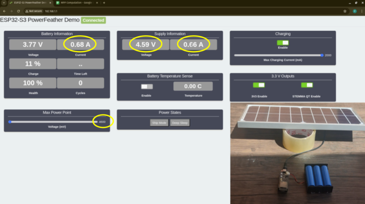 Battery current, supply voltage & current with MPP voltage not set
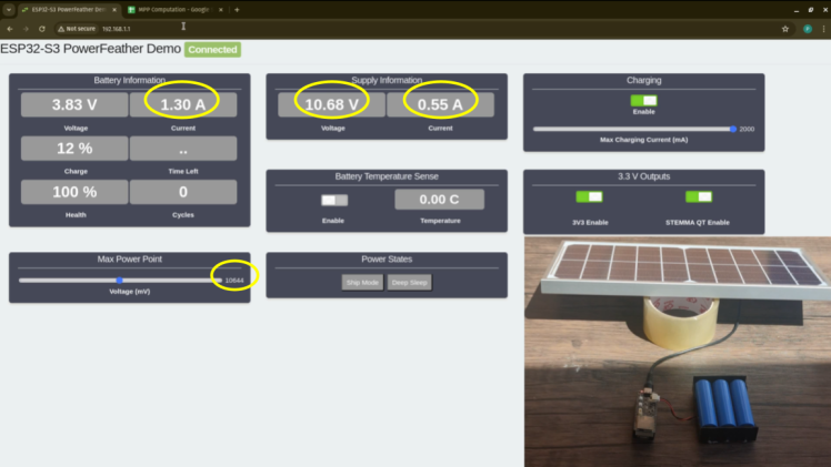 Battery current, supply voltage & current with MPP voltage set
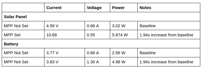
Setting the MPP voltage leads to a significant increase in power extracted from the solar panel and delivered to the battery, illustrated in the table below.
Conclusion
Users can play around with the power management and monitoring features of the ESP32-S3 PowerFeather using the demo app. These demonstrations are shown in action in the ESP32-S3 PowerFeather showcase video:
There's other information in this showcase video, so please use the timestamps to skip ahead to the parts you are interested in.
More information about the ESP32-S3 PowerFeather on the documentation website.
Code
Credits
PowerFeather
Low power, solar capable, Li-ion/LiPo powered IoT development boards in a Feather-compatible format.
Related products


Leave your feedback...