


Enhiker

Made by mukesh-sankhla / 3D Printing / Environmental Sensing / Sensors / Weather / IoT
About the project
A Portable Smart Weather Decision Maker
Items used in this project
Hardware components
View all
Story
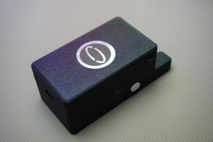
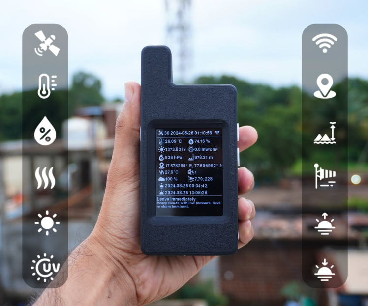
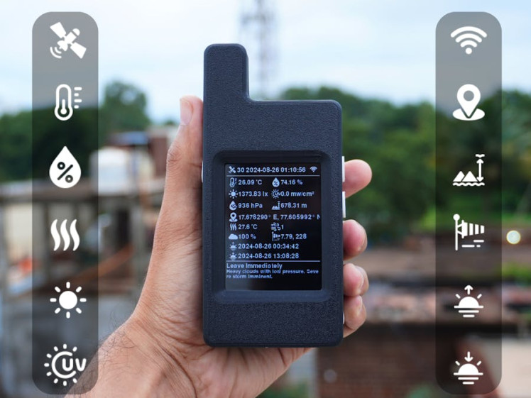
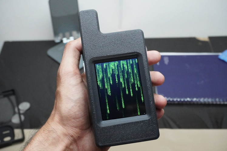
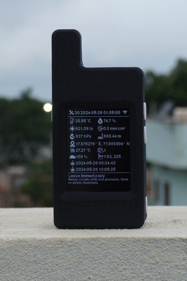
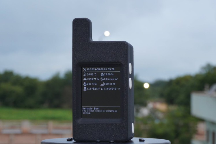
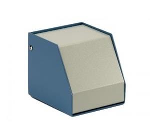
Enhiker is a compact, 3D-printed device designed to assist outdoor enthusiasts in making informed decisions about their environment. Powered by Unihiker from DFRobot, it integrates environmental and GNSS sensors to assess real-time weather conditions and location data. Enhiker provides users with a clear recommendation on whether it's safe to set up camp or continue outdoor activities based on health and safety parameters.
The device features a touchscreen display that shows a comprehensive set of weather and environmental metrics, including Current date and time in UTC, Temperature, Humidity, Ultraviolet Intensity, Luminous Intensity, Atmospheric Pressure, Elevation, Latitude & Longitude, Altitude, Heat Index, Satellites. When connected to WiFi, Enhiker accesses additional data from openweathermap API, displaying: Air Quality, Wind Speed, Wind Direction, Sunrise & Sunset, Cloud Coverage.
Beyond its weather-monitoring capabilities, Enhiker functions as an emergency power bank and can be recharged via solar panel, making it an essential tool for any outdoor adventure. Additionally, it logs all collected data with timestamps and location coordinates into a CSV file, making it valuable for meteorological and agricultural research.
Enhiker is a versatile and reliable companion for anyone exploring the great outdoors, ensuring safety and preparedness in any environment.
Sponsored By NextPCB
This project was made possible thanks to the support from NextPCB, a trusted leader in the PCB manufacturing industry for over 15 years. Their engineers work diligently to produce durable, high-performing PCBs that meet the highest quality standards. If you're looking for top-notch PCBs at an affordable price, don't miss NextPCB!
NextPCB's HQDFM software services help improve your designs, ensuring a smooth production process. Personally, I prefer avoiding delays from waiting on DFM reports, and HQDFM is the best and quickest way to self-check your designs before moving forward.
Explore their DFM free online PCB Gerber viewer for instant design verification:
Supplies
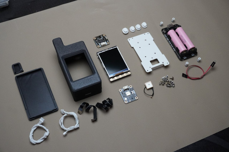
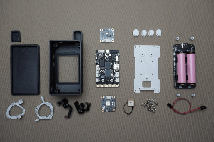
- 1x Unihiker
- 1x GNSS GPS BeiDou Receiver Module
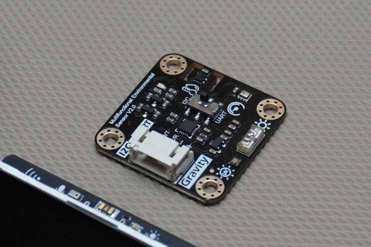
- 1x Environmental sensor
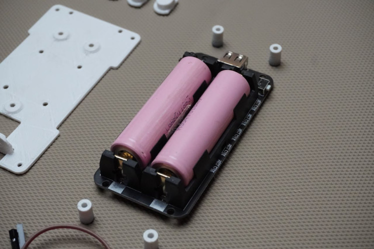
- 1x 2 Cell 18650 Battery Holder
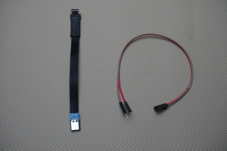
- 2x Type-C L-Shaped Male to Female Extension Cable
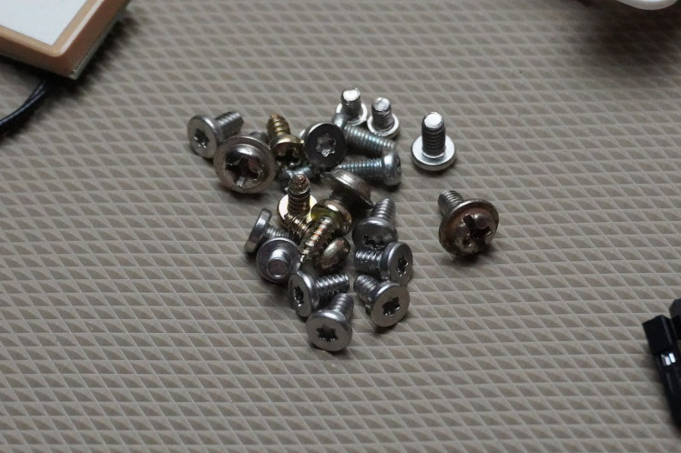
- 1x Screws and Nuts Kit
- 1x Jumper Wires pack
- 2x 18650 Battery Cell
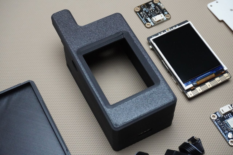
Step 1: CAD & 3D Printing
To begin, I designed the Enhiker using Fusion 360. You can view the design directly in your browser and download it to open in Fusion 360 for any modifications or creative additions. Feel free to customize and enhance the design as you like!
For 3D printing, you can directly download the STL files listed below:
- 1x Housing.stl
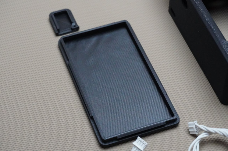
- 1x Cover.stl
- 1x Board_Plate.stl
- 1x Antenna_Cover.stl
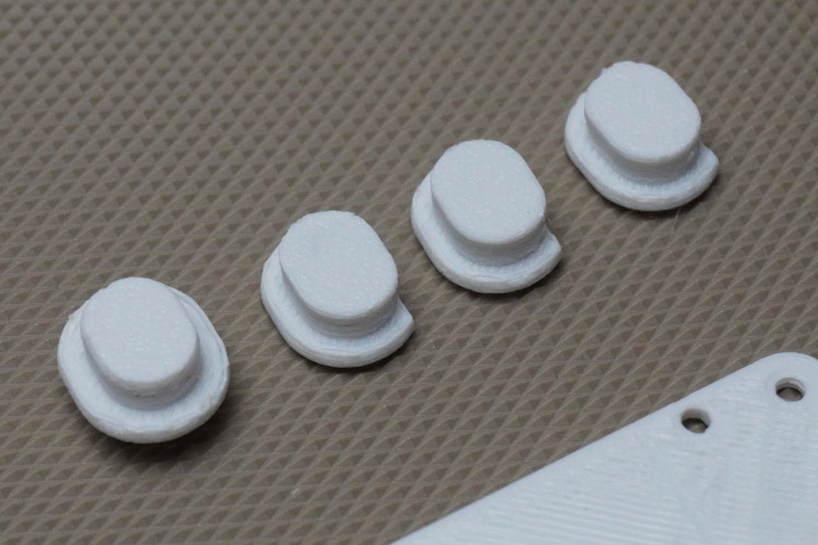
- 3x Button1.stl
- 1x Button2.stl
- 4x Spacer.stl
I used my Anycubic Kobra printer with matte black PLA filament for the printing process.
Step 2: Power Connection
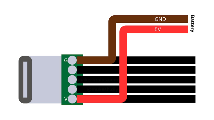
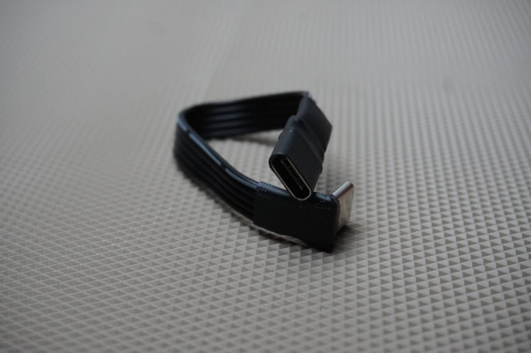
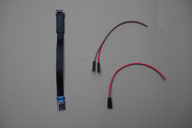


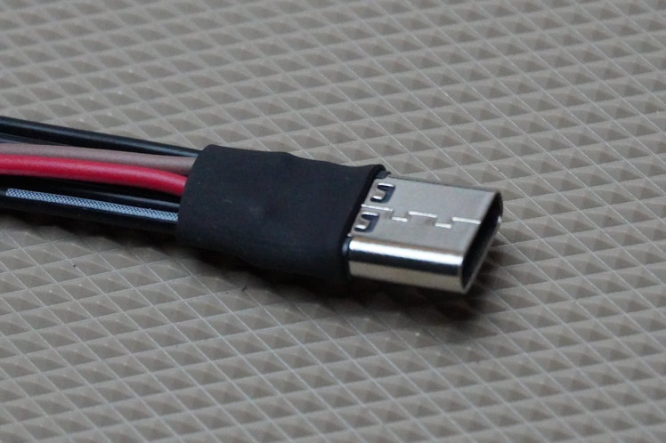
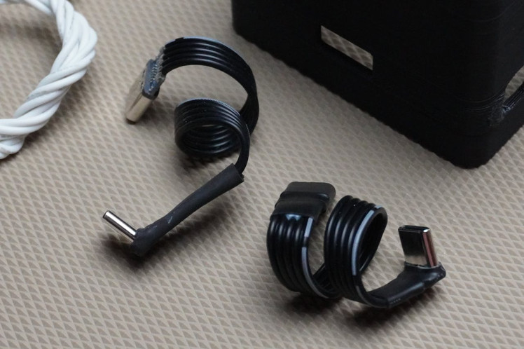
To power the Enhiker, we are using a "2 Cell 18650 Battery Manager". Since the Unihiker can be powered via USB Type-C, we are utilizing a Type-C extension cable, which has been modified to serve two purposes: providing power from the batteries and connecting to a PC for accessing and programming the Unihiker.
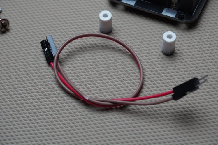
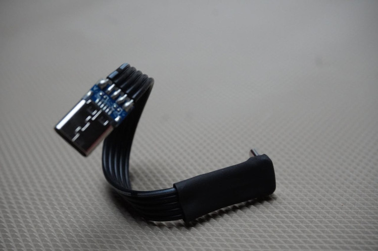
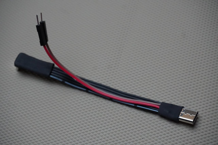
To modify the extension cable, follow these steps:
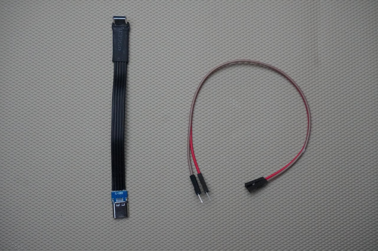
- Take two male-to-female jumper wires and cut them in half.
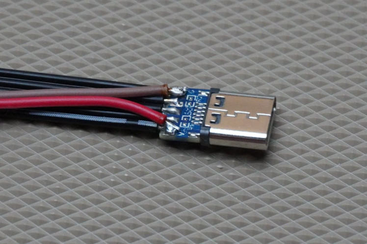
- Remove the heat shrink from the female side of the extension cable.
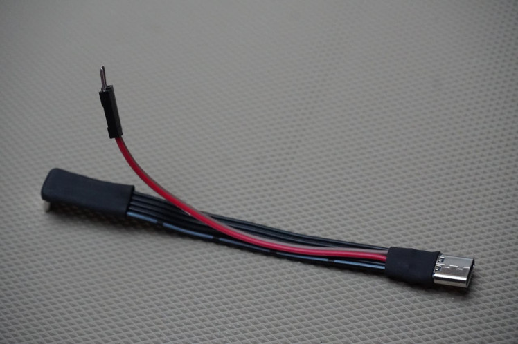
- Solder the male jumper wires as shown in the diagram above.
- Once soldered, cover the exposed parts with heat shrink tubing to ensure safety.
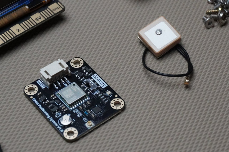
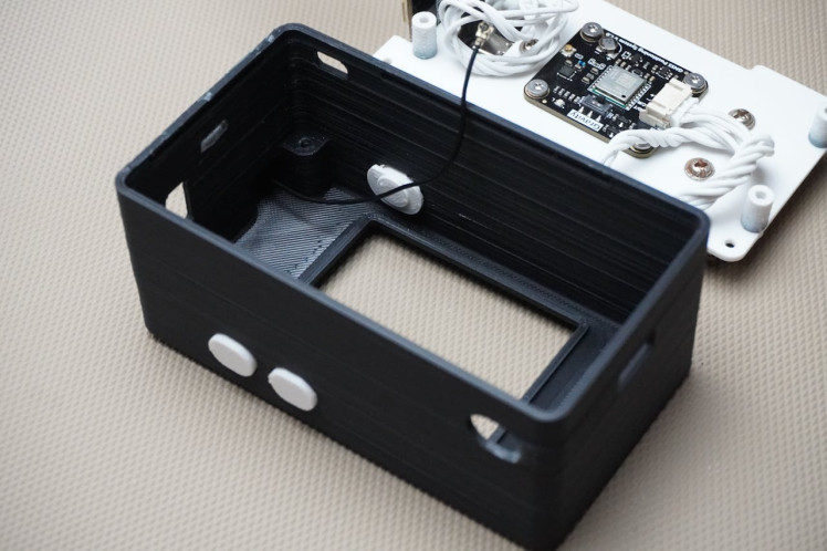
Step 3: Antenna Assembly
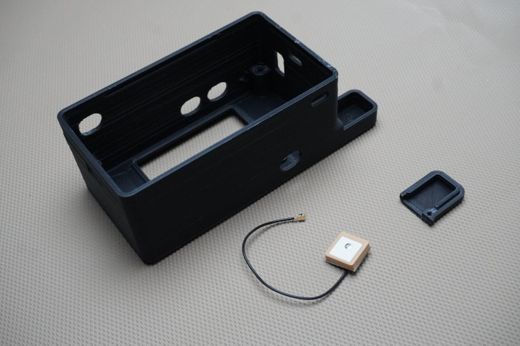
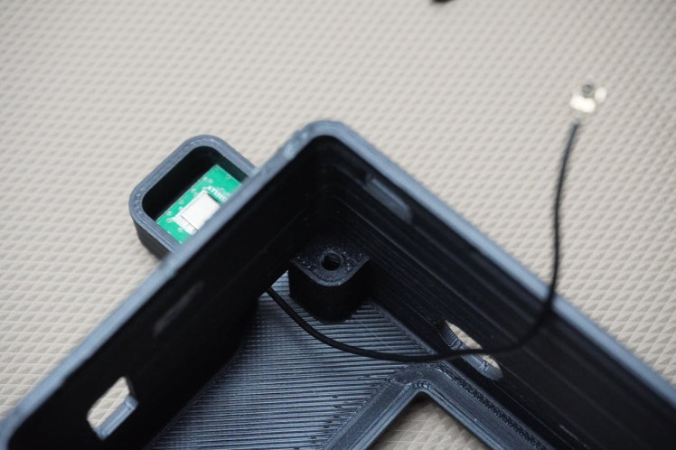
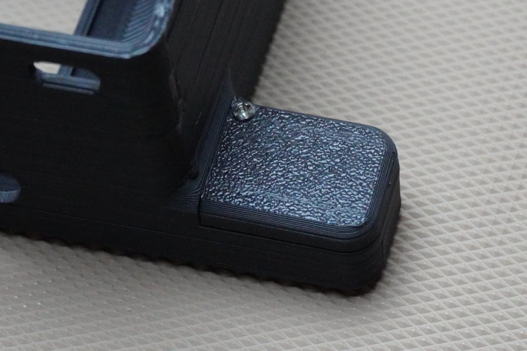
- Position the antenna in its designated spot, ensuring that the antenna wire is routed inside the housing.
- Place the 3D-printed antenna cover over the antenna.
- Secure the cover in place using a screw.
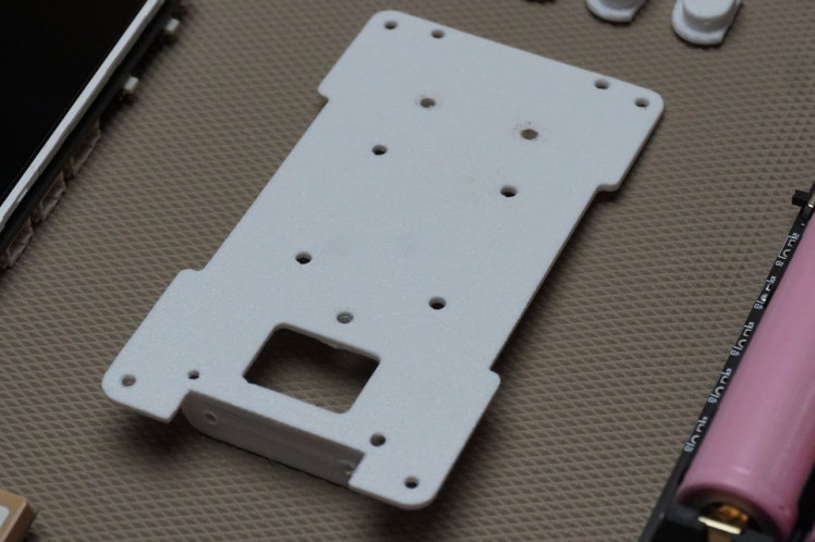
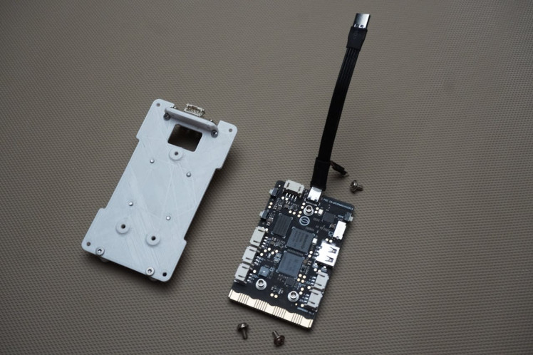
Step 4: Board Plate Assembly
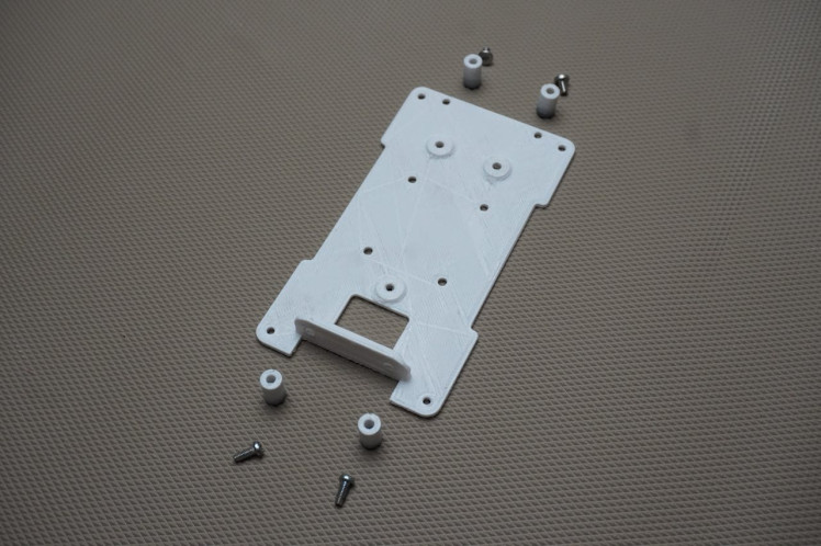
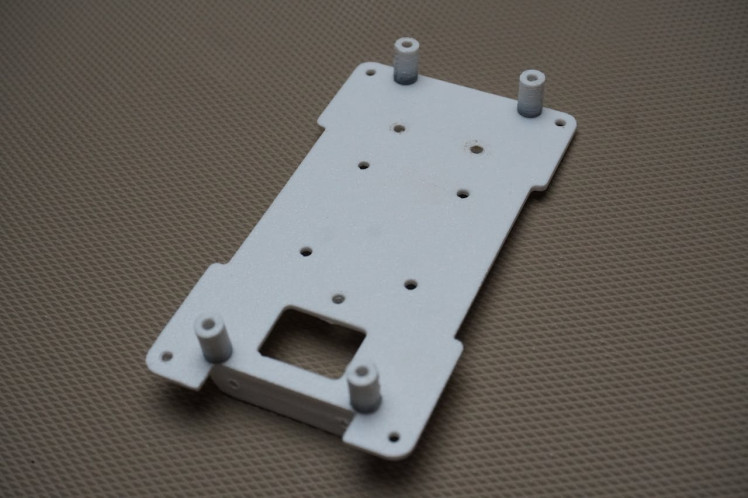
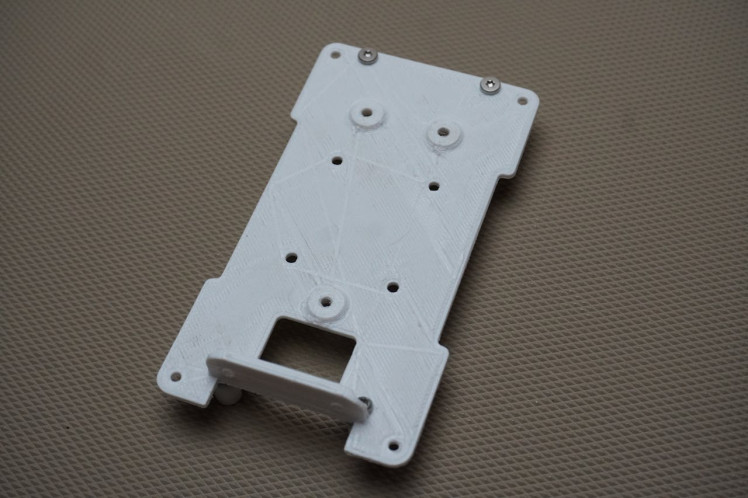
Next, let's prepare the board plate, which serves as the skeleton of the project and the mounting base for all components.
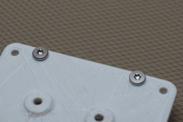
- Take the 4 spacers that were 3D-printed.
- Secure each spacer to the bottom side of the board plate using M3 screws.
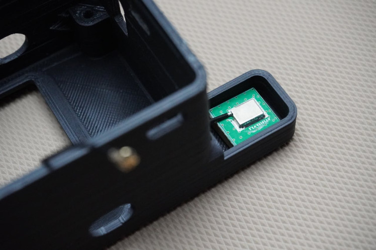
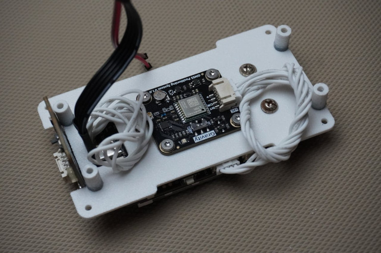
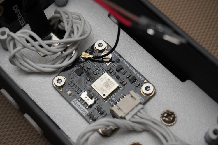
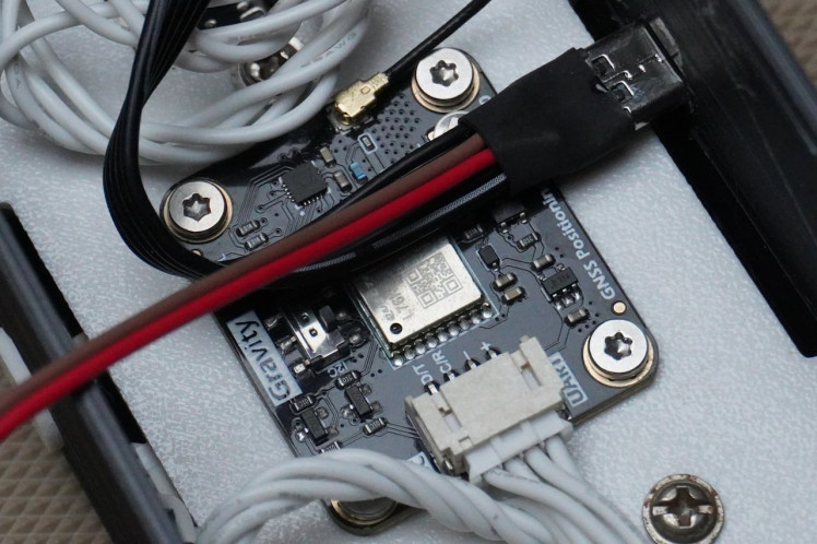
Step 5: Sensors Assembly
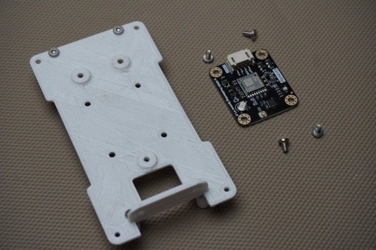
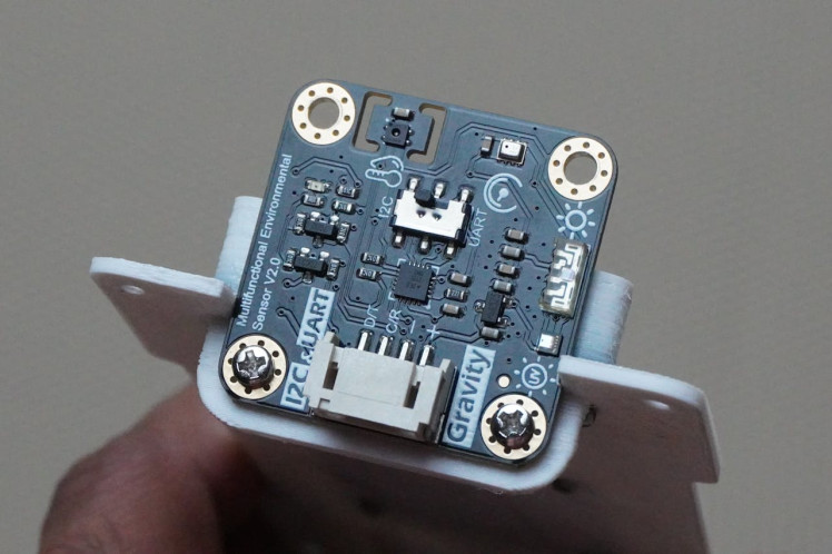
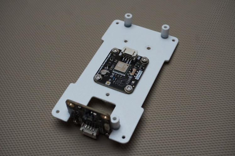
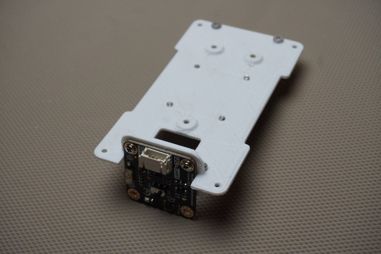
In this step, we will mount the Environmental and GNSS sensors onto the base plate.
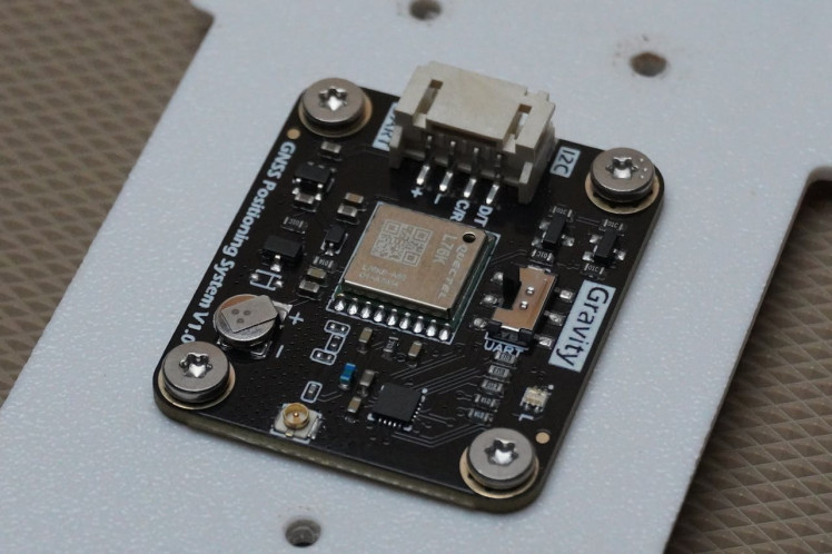
- Position the GNSS sensor in the center of the base plate towards the bottom side.
- Align the holes on the sensor with those on the base plate.
- Secure the GNSS sensor using 4 M3 screws.
- Place the Environmental sensor onto the designated bracket on the base plate and secure it in place using 2 M3 screws.
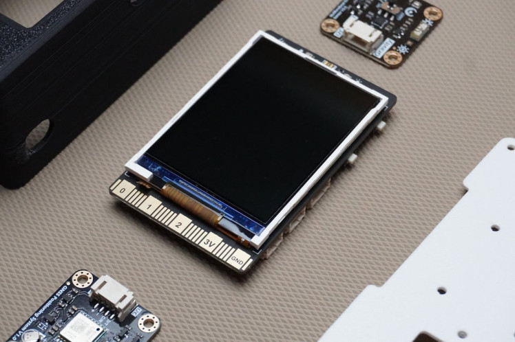
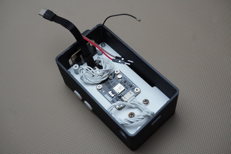
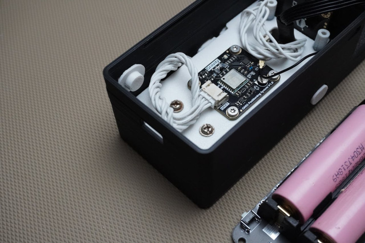
Step 6: Unihiker Assembly
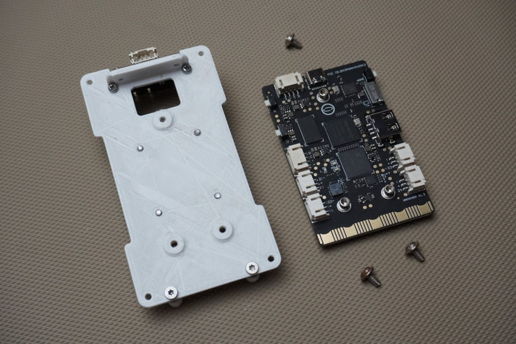

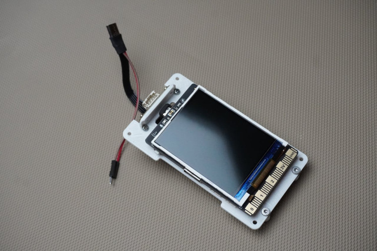
Now it's time to mount the Unihiker onto the base plate.
- Before mounting, plug in the Type-C extension cable that was prepared earlier.
- Position the Unihiker on the base plate, aligning it with the three designated holes.
- Route the cable through the designed slot on the base plate.
- Secure the Unihiker in place using M3 screws.
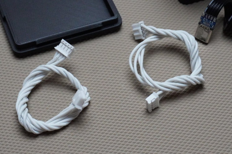
Step 7: Sensors Connection
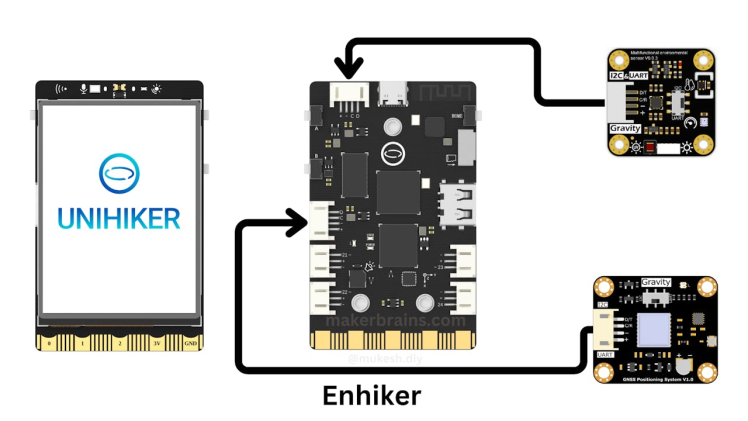
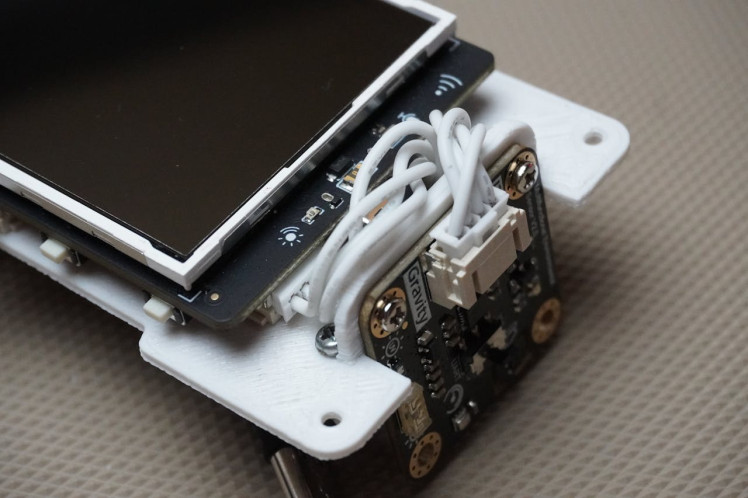
- Connecting the sensors to the Unihiker is simple and hassle-free, thanks to Unihiker's plug-and-play connectors, which make it easy to connect DFRobot sensors without worrying about wire alignment.
- Use two 4-pin connectors that came with the Unihiker to plug both the Environmental and GNSS sensors into the Unihiker as shown in the diagram.
- These sensors will communicate with the Unihiker via the I2C protocol.
- Ensure that the small switch on each sensor is positioned towards the "I2C" setting.
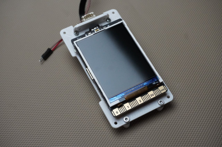
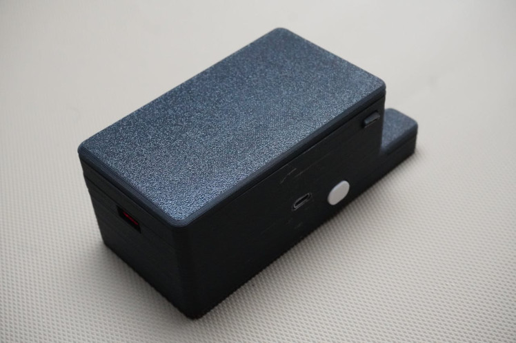
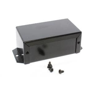
Step 8: Housing Assembly
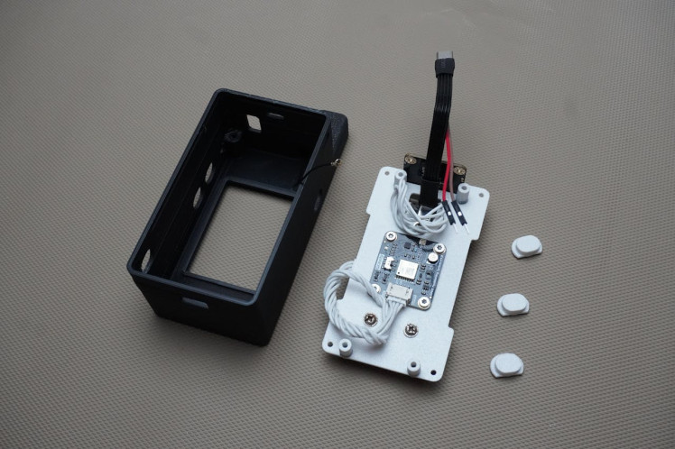
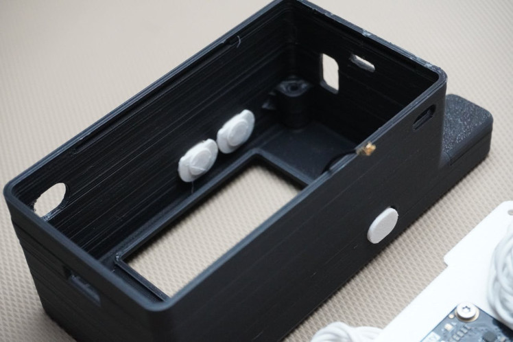
Now it's time to assemble everything into the housing.
- Begin by placing the 3D-printed buttons into their designated holes in the housing.
- Use masking tape to temporarily hold the buttons in place, as they might fall out during the assembly process.
- Carefully position the base plate assembly inside the housing, aligning the buttons and routing the antenna wire.
- Secure the base plate to the housing using 4 M3 screws.
- Once the base plate is secured, remove the masking tape holding the buttons.
- Finally, connect the antenna wire to the GNSS sensor.
Step 9: Battery Assembly
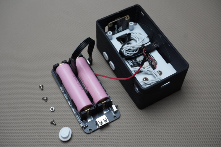

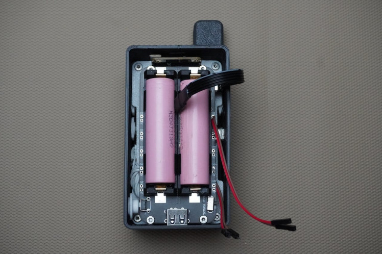
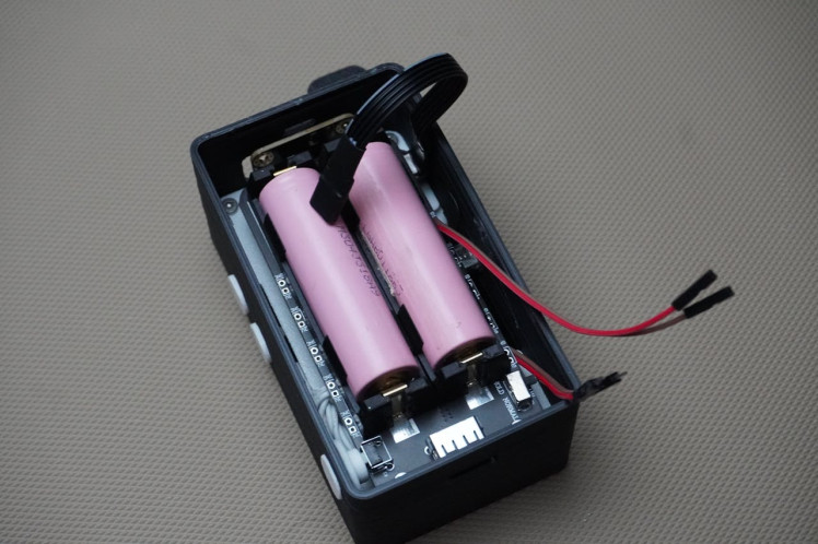
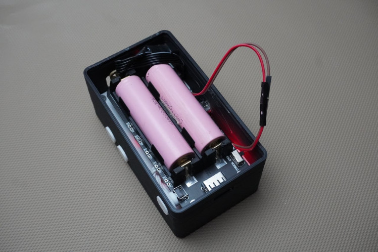
- Solder the two female jumper wires (previously cut) to the GND(Brown/Black) and 5V(Red) terminals of the battery maintain the color code of the wire.
- Plug the Type-C extension cable into the battery. This cable will be used for charging the batteries.
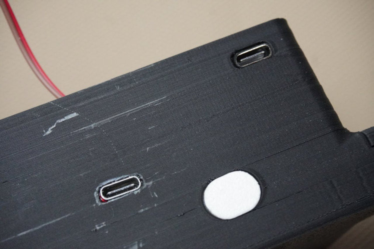
- Position the Unihiker's Type-C female connector into the middle slot of the housing body and secure the connector using hot glue.
- Insert the Button 3D printed into its designated slot in the housing.
- Place the battery manager board onto the spacers, by aligning the USB ports with its corresponding opening in the housing and secure the board with 4 M3 screws.
- Connect the female jumper wires to the male jumper wires of the Unihiker. (Please double check the Unihiker and battery connection before connecting as the wrong connection might permanently damage the components)
- Insert the battery's Type-C cable into its designated slot in the housing and secure the cable using hot glue to keep it in place.
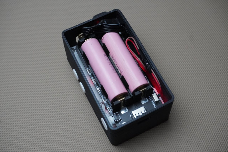
- Make sure that the switch on battery management board is positioned at Hold.
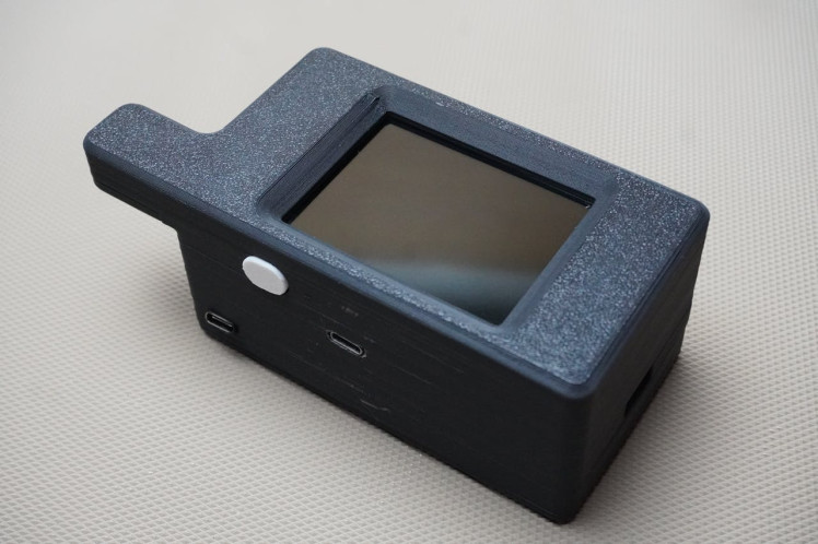
Step 10: Final Assembly


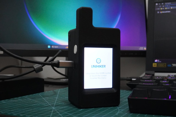
Before proceeding with the final assembly, power on the system to ensure everything is functioning correctly.
If the Unihiker board powers up, it indicates that all connections are properly made.
If the board does not power up, double-check all connections to identify and correct any issues.
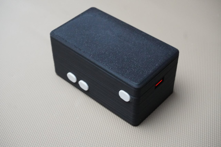
Carefully tuck all the wires into the housing, making sure they are neatly arranged and not pinched and snap the cover onto the housing, ensuring it fits securely.
And that's it! The assembly of your Enhiker is now complete.
Step 11: Setup and Programming
Now that's everything is assembled and working, lets program the board:
- Download and install Mind+ from here.
- Connect your Unihiker (or "Enhiker"!) to your PC using a USB cable.
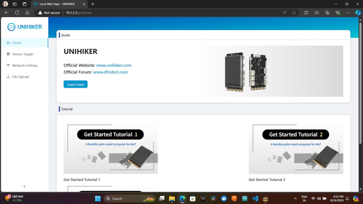
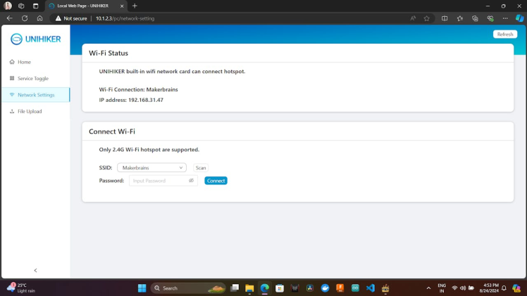
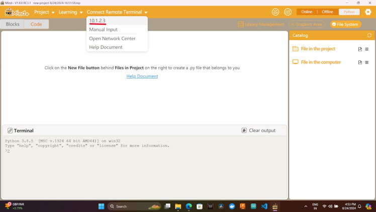
- Open a browser (any browser except Internet Explorer) and navigate to http://10.1.2.3 to access the local web page menu on the Unihiker.
- Go to the "Network Settings" on the web page and connect the Unihiker to your Wi-Fi network by entering your network credentials.
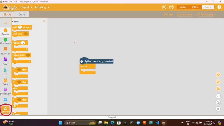
- Open the Mind+ software.
- Click on "Extensions" located at the bottom left side of the screen.
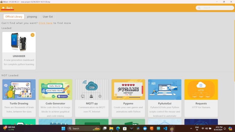
- Select "Unihiker" and then click "Back" to return to the main menu.
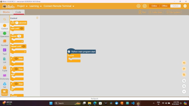
- Click on "Code" in Mind+ and then connect the Remote Terminal.
- Once connected, you will see the Unihiker's file system on the right side of the screen.
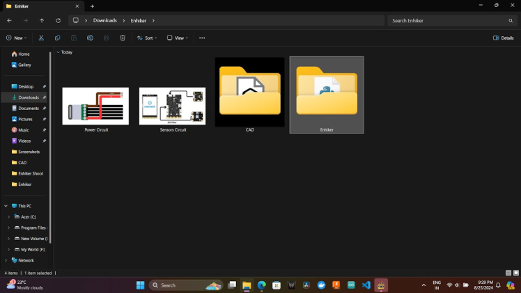
- Download the code from this GitHub repository and unzip the files.
- Drag and drop the entire Enhiker folder into the Unihiker's file system. This will copy the folder to the Unihiker.


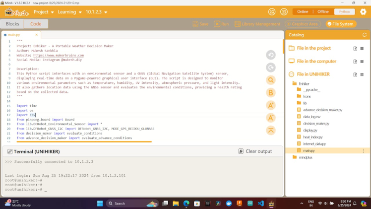
- Open the main.py file in the Unihiker's file system.
- Go to OpenWeatherMap and log in to your account.
- Navigate to "My API Keys" and copy your API key.
- Paste the API key in the main.py file
# Your API Key
API_Key = '***************************'
Run the main.py file.
The program should execute without issues, as the packages used are the default ones that come pre-installed on the Unihiker.
If any issues arise, check the folder structure and the installed packages.
Step 12: On Boot Setup
Enable Auto Boot:
- Press the "Home" button on the Unihiker.
- Navigate to 3-Service Toggle -> Auto Boot and enable it.
Set the Program to Run on Boot:
- Navigate to 2-Run Program -> root/ -> Enhiker/ -> main.py.
- Press the "Home" button to execute the program.
The Auto Boot feature will automatically run the last program that was executed.
Now, whenever the Enhiker is powered on, it will automatically run main.py by default.
Conclusion
Enhiker may not be a groundbreaking innovation in the rapidly evolving world of smartphones and advanced technology, but it serves a unique purpose by offering valuable lessons in IoT, communication, and offline functionality-features that many modern devices often overlook. This project stands out for its ability to operate independently of the internet, making it a reliable companion for those who venture into the great outdoors where connectivity is limited.
Whether you're an outdoor enthusiast, an engineer, or a professional in meteorology or agriculture, Enhiker is a practical tool worth considering. It bridges the gap between technology and nature, providing essential data and insights in environments where conventional tech falls short.
Thank you! See you next time ;)
Schematics, diagrams and documents
CAD, enclosures and custom parts
Code
Credits
mukesh-sankhla
Tech Educator | Content Creator | Developer | Maker - Simplifying technology through hands-on learning. Creating high-quality tutorials, projects, and insights on electronics, IoT, robotics, CAD, 3D printing, and software development at Empowering students, professionals, and makers with practical, accessible, and inspiring content.
Related products


g