


Diy Wireless Hi-fi Bluetooth Audio Player
About the project
Using Wireless Hi-Fi Amplifier Module to DIY a Simple Bluetooth Audio Player
Project info
Difficulty: Moderate
Platforms: Arduino
Estimated time: 2 hours
License: GNU General Public License, version 3 or later (GPL3+)
Items used in this project
Hardware components

Story
The wireless HI-FI module is a Class AB/Class D audio switching module with an output power of 5.3W, a single-channel audio amplifier board, built-in Bluetooth, FM, USB, AUX line and memory chip decoder.
The module has abundant input ports and outstanding features such as compact, beautiful design and high-quality sound quality, making it stand out from many development boards. Its versatility makes it the first choice for various applications.
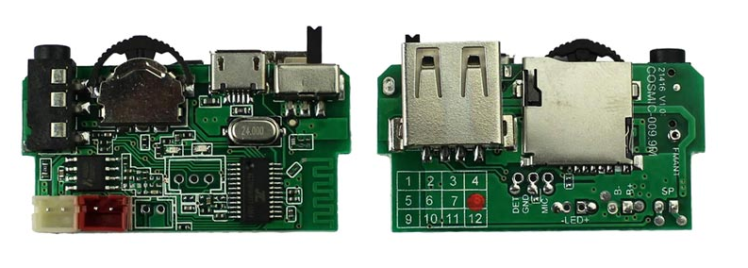
A power switch to turn on/off the module.
A Micro-USB charging interface with a fixed input voltage of 5V.
An AUX line 2.5mm female input jack.
A USB card, TF card input port.
Built-in Bluetooth and FM support.
A multi-function switch.
It has two built-in red and green LED indicators (their functions will be introduced later).
The module has more internal options that can be used to support other functions. The module also has two open interfaces for connecting microphones and an additional LED indicator for power indication, as shown in the figure below.
Connecting an additional LED light to the board will not have much effect as it only indicates the on/off state based on the power switch.
Soldering a small piece of wire to the FM antenna terminals can improve the signal and sound quality in FM mode.
Connecting a microphone is very practical and futuristic for the project. It allows talking while the module is connected to the smartphone via Bluetooth or AUX.
Connect the battery to the battery connector of the module. You can use a 3.7 volt Li-ion battery or a 4 volt lead-acid battery.
Battery Input Voltage Range: With this module, you can view the battery consumption percentage on your smartphone. This feature is completely based on the remaining battery voltage sensed by the controller IC.
When the voltage is 3 volts, the system displays that the battery is completely drained [0%]; when the voltage is 4.2 volts, the system detects that the battery is fully charged [100%].
Up to 5 volts can be supplied to the battery terminals of the module to improve the sound quality performance of the audio IC.
NOTE: The module can also be powered directly from the Micro-USB charging connector, which has a fixed input voltage of 5 volts, without the need for any batteries.
Speaker matching specifications
This module uses HAA2018 audio IC, whose Vdd range is 2.5-5.5 V. It is a single-channel audio power amplifier IC with class AB/class D switching function and 5.3W output power. Its technical specifications are as follows:
Class D output power:
5.3W (VDD=5.0V, RL =2Ω, THD+N=10%)
3.2W (VDD=5.0V, RL =4Ω, THD+N=10%)
Class AB output power:
5.2W (VDD=5.0V, RL =2Ω, THD+N=10%)
3.1W (VDD=5.0V, RL =4Ω, THD+N=10%)
RL represents the load impedance, and VDD represents the battery terminal voltage of the audio IC.
Other features:
Low distortion, low noise
POP sound suppression function at startup
Shutdown current is less than 1uA
Overheat protection function
From the above technical parameters, it can be seen that the output power is maximum when the load impedance is 2Ω. If possible, it is recommended to use a speaker with an impedance matching the output impedance of the amplifier. In addition, choosing a speaker with a rated power equal to or higher than the output power of the amplifier will provide better performance and reduce the risk of damaging components.
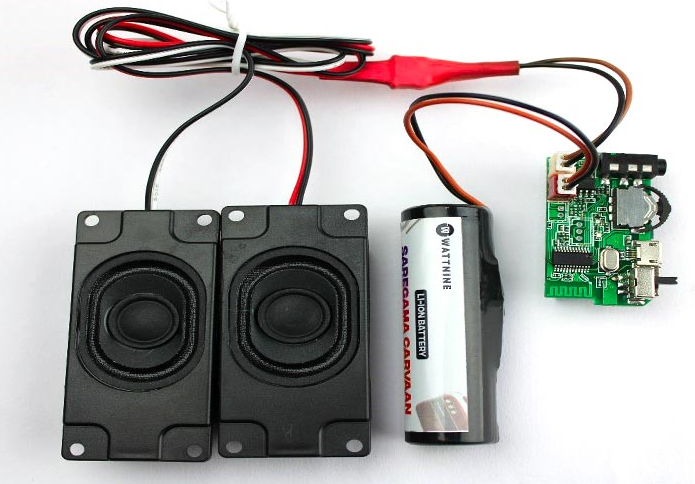
Since my amplifier is rated at 2Ω 5W, I use two 4Ω 2.5W speakers in parallel to make it the same as the output power of the amplifier.
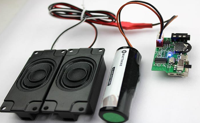
Let's take a look at the real circuit prototype in the figure below.
Bluetooth Audio Amplifier Board Demonstration
Connect the lithium-ion battery correctly and pay attention to the positive and negative connections. In addition, please connect the speaker correctly for the best sound quality.
Turn on the switch and check if the blue LED indicator flashes.
Mode and LED Indicator
The module works in five different modes, namely Bluetooth mode, FM mode, AUX mode, U disk mode and SD card mode. The blue LED indicator indicates slightly differently in each mode
Bluetooth mode: The module is always in Bluetooth mode by default after turning on the amplifier board.
The blue LED indicator flashes quickly until Bluetooth pairing fails.
After pairing or when pausing a song, the LED indicator lights up continuously.
Flashes slowly when playing a song.
FM mode: Switch to FM mode by pressing and holding the multi-function button and pressing toward the center.
The blue LED flashes quickly until all channels are scanned.
Flashes slowly when playing a channel.
USB/SD card mode: After inserting a USB flash drive, the module will automatically start USB flash drive mode.
The LED lights up continuously when pausing a song or when there is no song in the USB flash drive.
Flashes slowly when playing a song.
Note: There must be MP3 songs in the USB flash drive, otherwise the USB flash drive cannot be accessed.
AUX mode: Connect the AUX cable to provide audio input from the smartphone to the development board.
Always flashes slowly when playing/pausing a song.
Charging Function
The module has a Micro-USB input port for charging the battery pack connected to the module. The red LED indicates the charging mode of the module. The red LED lights continuously when the battery is charging.
Battery terminal charging voltage: 4 V
Charging current: ∼200 mA
Credits

Related products


Leave your feedback...