Items used in this project
Hardware components
Story
 1 / 2
1 / 2
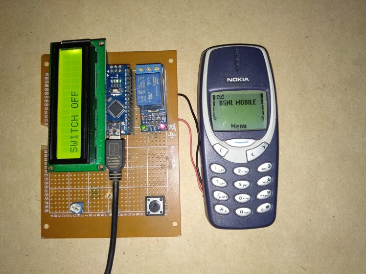
Ever wondered what to do with your old basic phones? The advent of a smartphone in last decade made all the basic phones obsolete. Even though they had good battery life and decent look they are less when compared to big smartphones which have big screens and lots of features. Even I had lots of these phones lying around. I did this project long back i.e 5 years back when I was in 11th grade. Here I did a slight advancement when I saw this old project. In this tutorial, I'll use an old basic phone as a remote switch which can be turned on and off from practically anywhere in the world. ( P.S: Where there is cellphone network)In India, the power supply is not 24x7 in many rural areas. Farmers in the rural area have to supply water to their fields consistently otherwise there might be the loss of crops due to water shortage. The fields are situated far away from their houses. Therefore this project aims to provide a solution for switching pump set remotely to help farmers. But this can be used to switch anything.
Step 1: Get the Parts
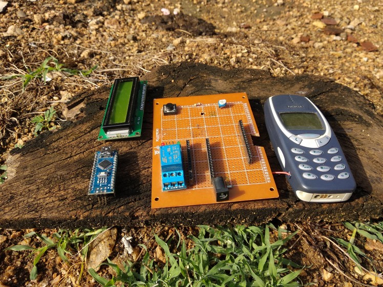
1. Old basic phone (I'm using legendary Nokia 3310)
2. Soldering Iron
3. Wires
4. Arduino Nano ( Any microcontroller is fine)
5. A relay module (5V 10A)6. Some LEDs
7. 16x2 display (optional)
8.Perf board
Step 2: Disassembly
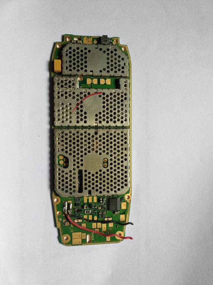
Now you need to disassemble your old phone so that you will have access to the vibration motor connections. I have attached a video of disassembly of Nokia 3310. But the procedure will be the same for almost all basic phones. Open one by one till you reach the main PCB. There you can see a vibration motor inside.
Step 3: Vibration Motors Inside
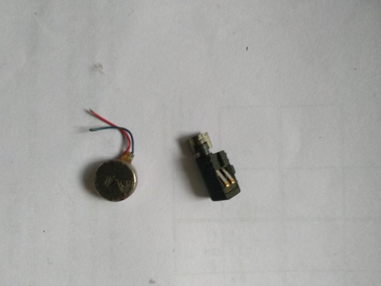
Vibration motor: It is used to provide haptic feedback to the user when a message or call comes. In vibration motors, there are two types,
1. Coreless motor with an unbalanced weight on the shaft. This results in a change in moment of inertia resulting in wobbling and hence the vibration.
2. Coin cell type vibration motor which is sealed. We have to find the connection points of vibration motors. And solder these points with 2 wires for extending it. Pretty much every basic phone has a vibration motor either of two types.
Step 4: Connecting It to Arduino
 1 / 2
1 / 2
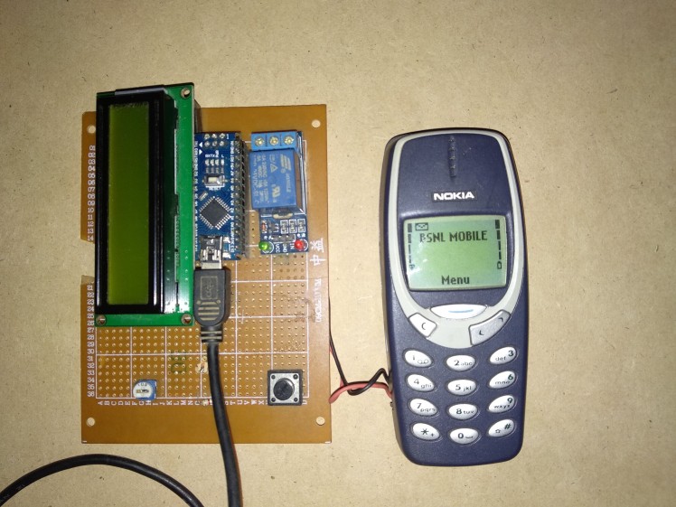
Connect these wires to one of the GPIOs of Arduino. Here I'm using pin number A0. And negative pin to ground. LCD connections are as usual. Relay module signal pin to pin number 4 and VCC, GND to Arduino's VCC and GND. You can use jumper wires for the connection here I have made a perf board circuit by soldering all components.
Step 5: Upload the Code
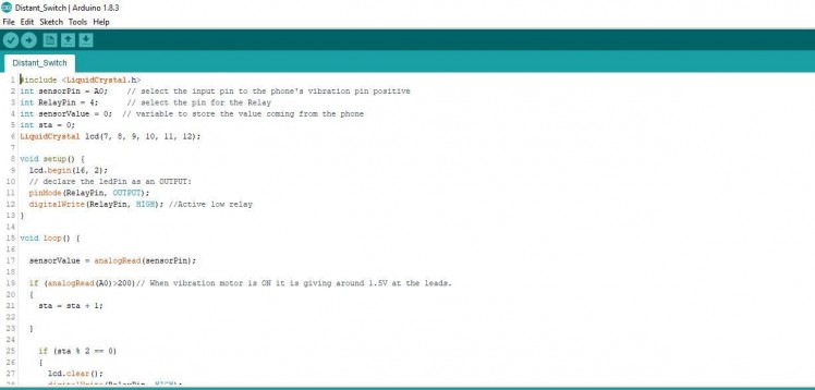
Here I will read the analog port and look for a high signal. And switch the pins accordingly. I have written everything in comments and code is self-explanatory. Whenever it reads a certain voltage at analog pin it activates the switch. This switch can be deactivated by again calling or by sending an SMS.
Step 6: Working Video
Here I have attached a working video of how the whole process works. I hope you enjoy recycling your old phone for a good purpose. Applications of this project are the following:1. Actuation of a pump set in an agricultural land 2. Switching your room heater before going home. 3. Switching your water heater for bathing 4. Turning off the main switch of your home remotely.And many more. Let me know if you guys find out anything else. The best part is you can trigger these switches from any part of the world where there is network access. Thanks a lot for reading. Don't forget to vote in contests.
Step 7: My Old Design
I just wanted to show my old design of switching circuit. Back in those days i.e when I was in 11th grade I didn't have access to a computer and I never knew about microcontroller. Everything was analog. I have uploaded a video about my switching mechanism. Here I had used a DC motor to get the signal from the phone. When call or message comes this will rotate the motor in one direction and motor's gear rotates a rack of gear which presses a soft push button which I had extracted from a DVD drive. When the pushbutton is pressed it completes the circuit leading to the switching on of small DC pump set (Extracted from Car's wiper water supply). This supplies water to the field in my demo. Then a water level controller circuit based on opamp senses the moisture level and when it crosses the threshold, it used to spin back the DC motor in other direction releasing the push button. This was the total control system I used in my older project.




Leave your feedback...