Connect Ad7606 8 Channel 16 Bit Adc In 16 Bit Parallel Mode
About the project
Arduino Mega and Visuino: Connecting AD7606 8 Channel 16 Bit bipolar analog to digital converter in 16 bit parallel mode - quick and easy.
Project info
Difficulty: Moderate
Estimated time: 1 hour
License: GNU General Public License, version 3 or later (GPL3+)
Items used in this project
Hardware components
Software apps and online services
Story
AD7606 is a very nice 8 Channel 16 Bit Bipolar Analog to Digital Converter manufactured by Analog Devices. The module has great many features, including Sample and Hold for the 8 Channels, per channel Analog filters, shared digital filter, and more. It is also capable of working in 3 different modes - 16 bit parallel mode, 8 bit parallel mode and Serial mode.
Few weeks ago I was asked to add AD7606 support for Visuino, and ICStation generously offered to send me one AD7606 Module. The module arrived, and I started working on the Visuino support. The module came pre-configured for 16 bit parallel interface, and I decided to add this first, before I start reconfiguring it for the other modes. The support was added to Visuino, but other priorities prevented me from making Tutorial for it. Finally I have found some time to make this Tutorial, and once done, I will see to re-configure the module and add support for the rest of the modes in Visuino.
Step 1: Understanding how the AD7606 works
1 / 2
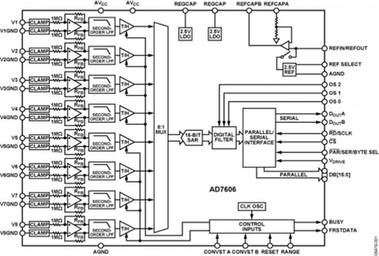
The AD7606 (Picture 1) is 16 bit ADC with 8 Bipolar channels (Each channel has its own ground, and can measure both positive and negative signals). It has Sample and Hold components for each channel, and individual per channel filters. It also has a shared digital filter.
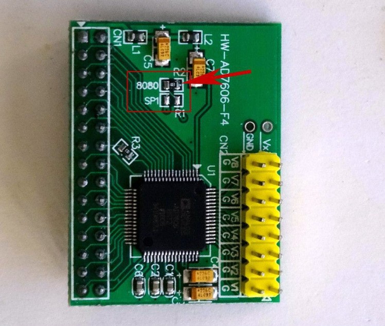
There are readily available modules with the AD7606, and I recently received one generously donated by ICStation(Picture 2).
The AD7606 can be configured to work in 3 different modes. 16 bit parallel, 8 bit parallel, and Serial.
The AD7606 Module that I received has the option to be configured in any of the 3 modes, by an SMD resistor (Picture 2). Unfortunately the labeling on the module is confusing or incorrect, and although the module from the picture appears to be configured for 8 bit parallel, it is actually configured for 16 bit parallel mode. I plan to move the resistor and reconfigure the module, so I can make Tutorials in 8 bit and Serial mode, but since there is a danger to damage the module in the process, I am first making this Tutorial with the 16 bit parallel mode.
Step 2: Components
1 / 3 • Picture 1
Picture 1
Picture 2
Picture 3
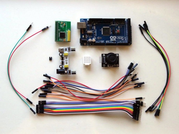
- One Arduino Mega - you need enough pins for the 16 bits of the data bus
- One small Breadboard (Any breadboard can be used, or any other way to connect 3 wires together)
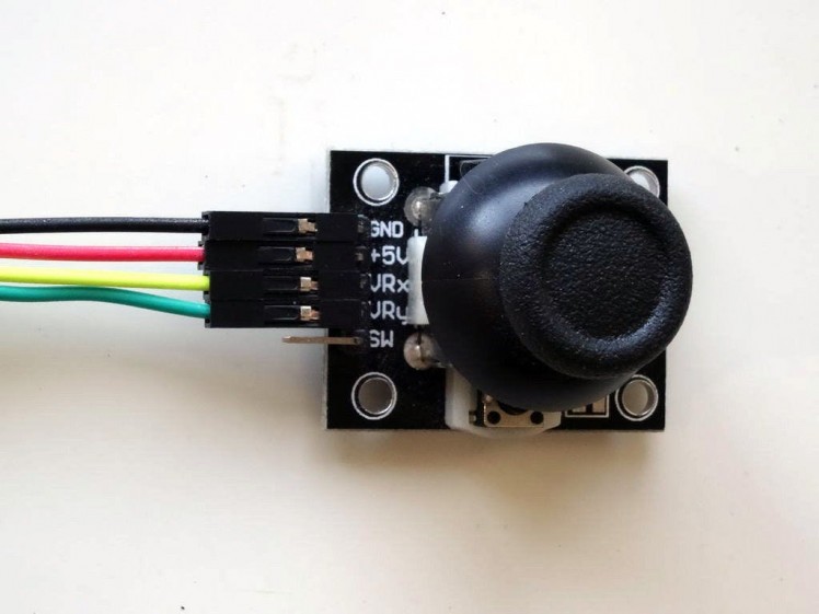
- One Joystick that I got from this cheap 37 sensors set (I use the Joystick to generate analog signals for the AD7606 Module. You can use any other source of +/- 5 V Analog signal to test)
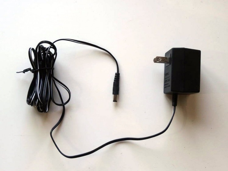
- One K2 Breadboard power supply with adapter (Picture 2)
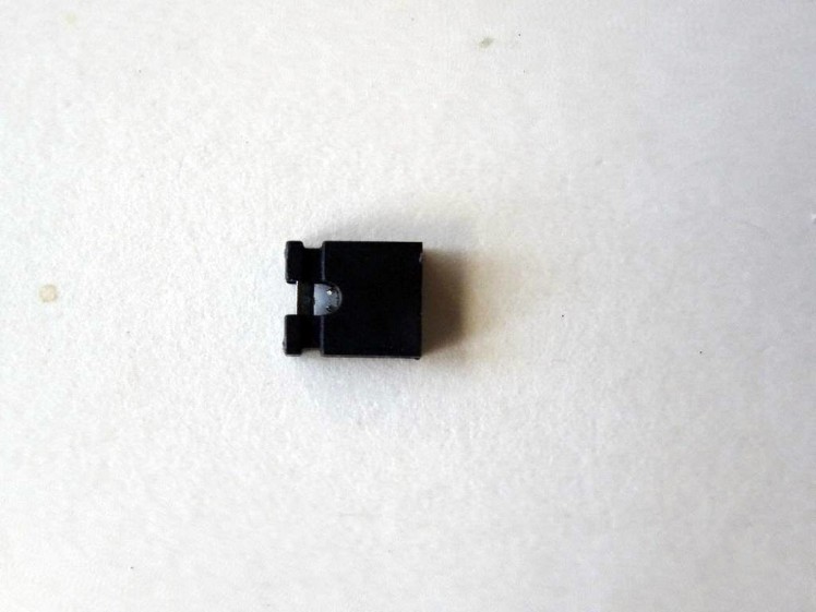
- One Jumper with open top (Picture 3) allowing a wire to be inserted from the top side between the pins
- 17 Female-Female jumper wires
- 29 Female-Male jumper wires
- 2 Male-Male jumper wires
- 5 Female-Female jumper wires
1 / 4 • Picture 1
Picture 1

Picture 2
Picture 3
Picture 4
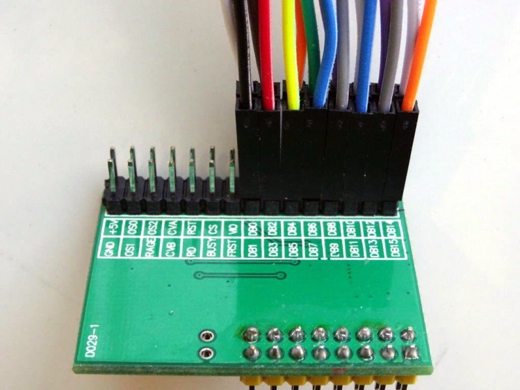
- Connect the Female ends of 16 Female-Male wires to the DB0 to DB15 pins of the AD7606 Module (Picture 1)
- Connect the Male end of the wires in the same order (DB0 to Pin 14) to the Digital pins 14 to 29 of the Arduino Mega board (Picture 2)
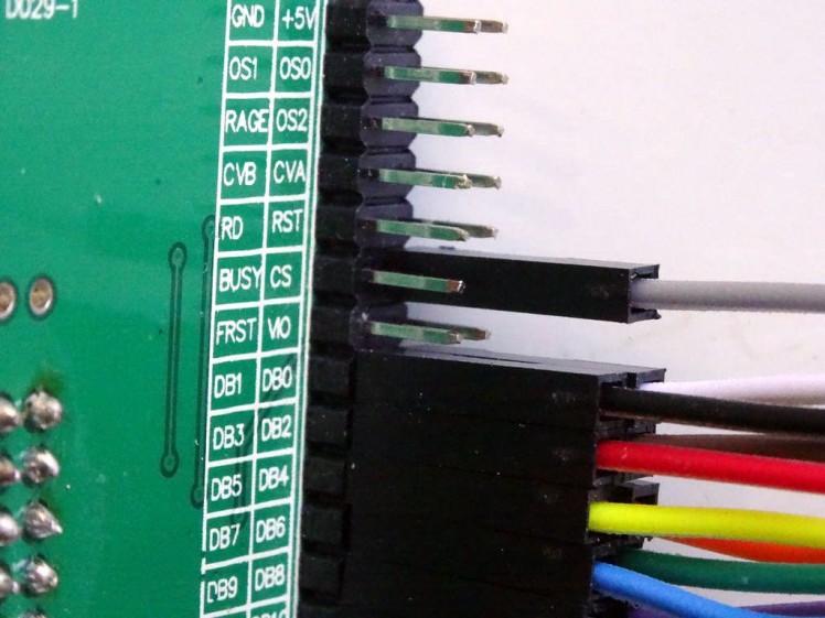
- Connect the Female end of a Female-Male(Gray wire) to the CS pin of the AD7606 Module (Picture 3)
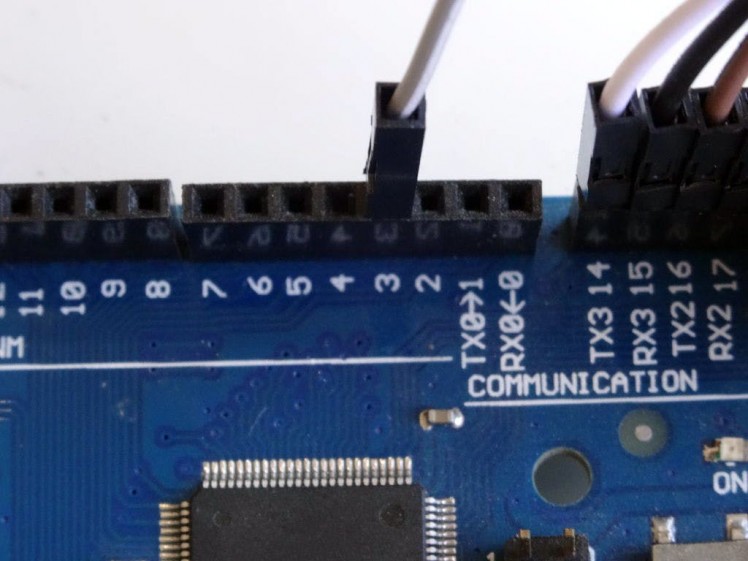
- Connect the Male end of the CS wire(Gray wire) to the Digital pin 3 of the Arduino Mega board (Picture 4)
1 / 4 • Picture 1
Picture 1
Picture 2
Picture 3
Picture 4
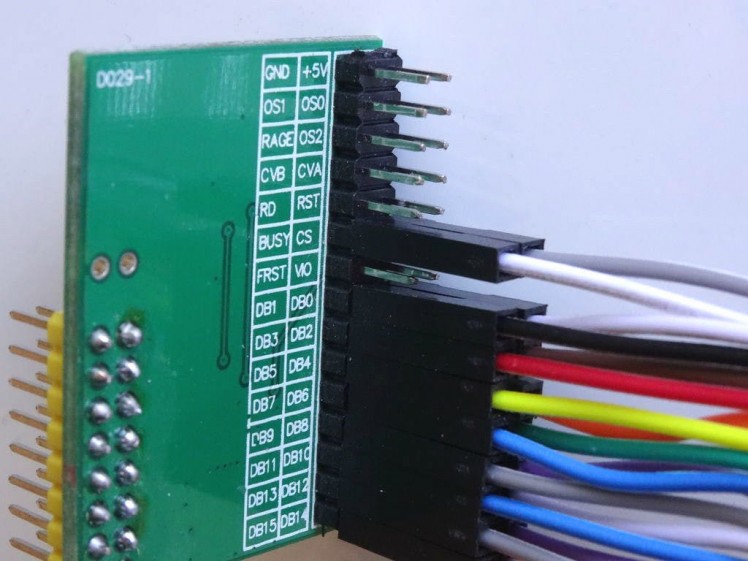
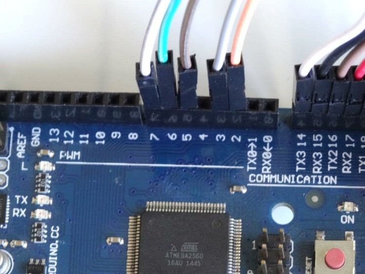
- Connect the Female end of a Female-Male(White wire) to the Busy pin of the AD7606 Module (Picture 1)
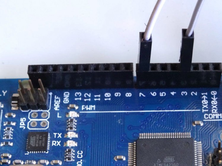
- Connect the Male end of the Busy wire(White wire) to the Digital pin 7 of the Arduino Mega board (Picture 2)
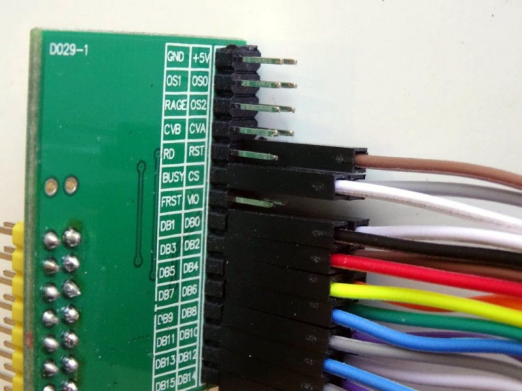
- Connect the Female end of a Female-Male(Brown wire) to the RST pin of the AD7606 Module (Picture 3)
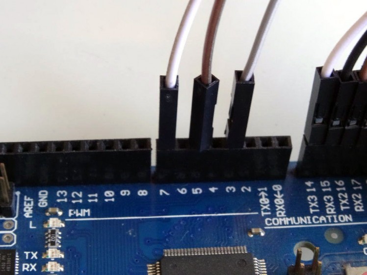
- Connect the Male end of the RST wire(Brown wire) to the Digital pin 5 of the Arduino Mega board (Picture 4)
1 / 5 • Picture 1
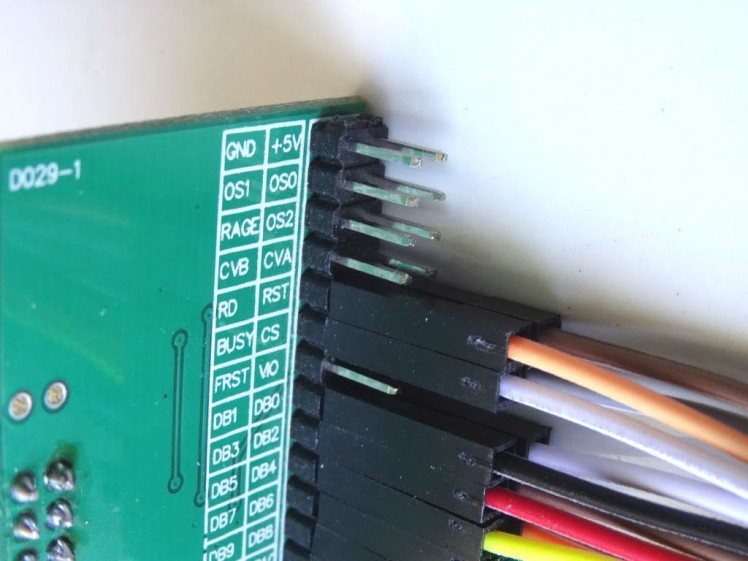
Picture 1
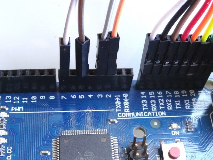
Picture 2
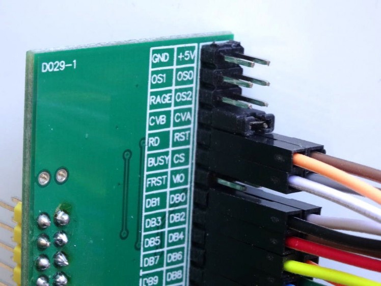
Picture 3
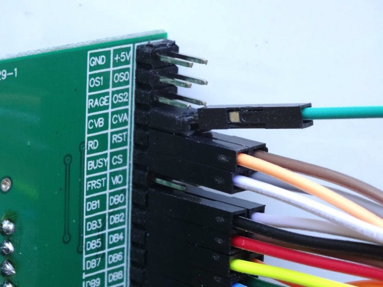
Picture 4
Picture 5
- Connect the Female end of a Female-Male(Orange wire) to the RD pin of the AD7606 Module (Picture 1)
- Connect the Male end of the RD wire(Orange wire) to the Digital pin 2 of the Arduino Mega board (Picture 2)
- Insert the Jumper with open top to connect the CVA and CVB signals of the AD7606 Module (Picture 3)
- Insert Male-Male(Green wire) in the center of the Jumper with open top between the CVA and CVB signals of the AD7606 Module so the wire will make electrical contact with both pins (Picture 4)
- Connect the Male end of the CVA/CVB wire(Green wire) to the Digital pin 6 of the Arduino Mega board (Picture 2)
1 / 4 • Picture 1
Picture 1
Picture 2
Picture 3
Picture 4
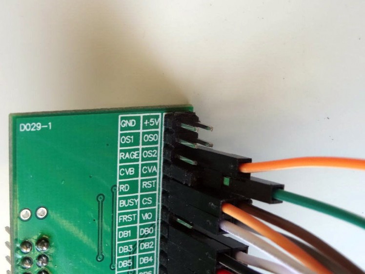
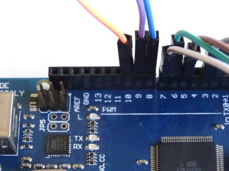
- Connect the Female end of a Female-Male(Orange wire) to the OS2 pin of the AD7606 Module (Picture 1)
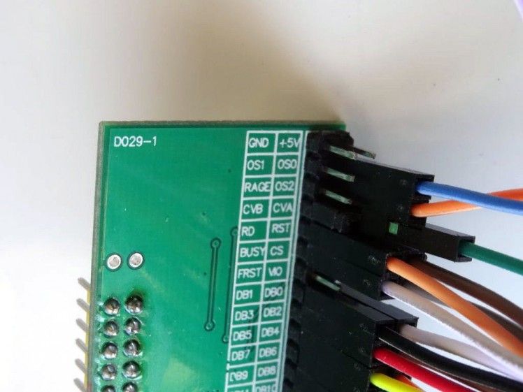
- Connect the Female end of a Female-Male(Blue wire) to the OS0 pin of the AD7606 Module (Picture 2)
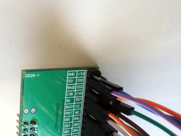
- Connect the Female end of a Female-Male(Purple wire) to the OS1 pin of the AD7606 Module (Picture 3)
- Connect the Male end of the OS0 wire(Blue wire) to the Digital pin 8 of the Arduino Mega board (Picture 4)
- Connect the Male end of the OS1 wire(Purple wire) to the Digital pin 9 of the Arduino Mega board (Picture 4)
- Connect the Male end of the OS2 wire(Orange wire) to the Digital pin 10 of the Arduino Mega board (Picture 4)
1 / 5 • Picture 1
Picture 1
Picture 2
Picture 3
Picture 4
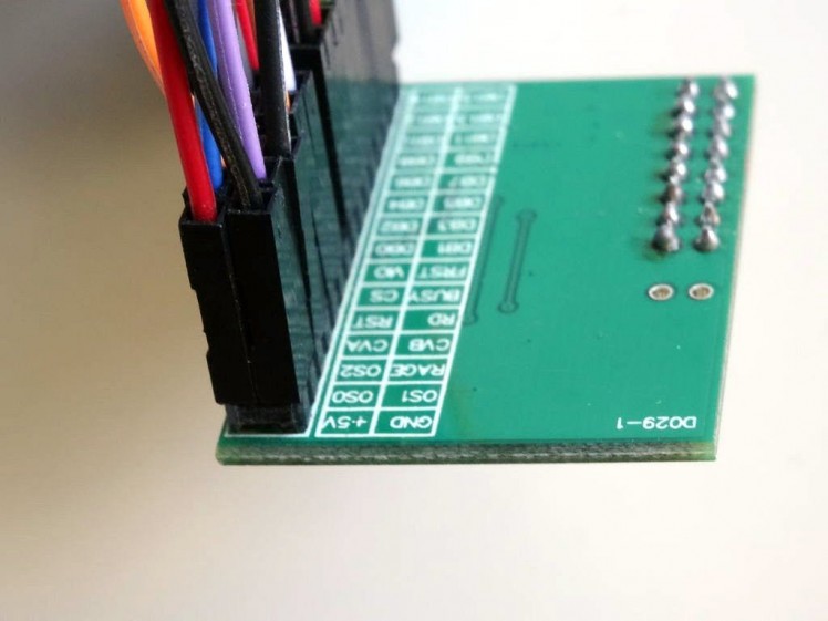
Picture 5
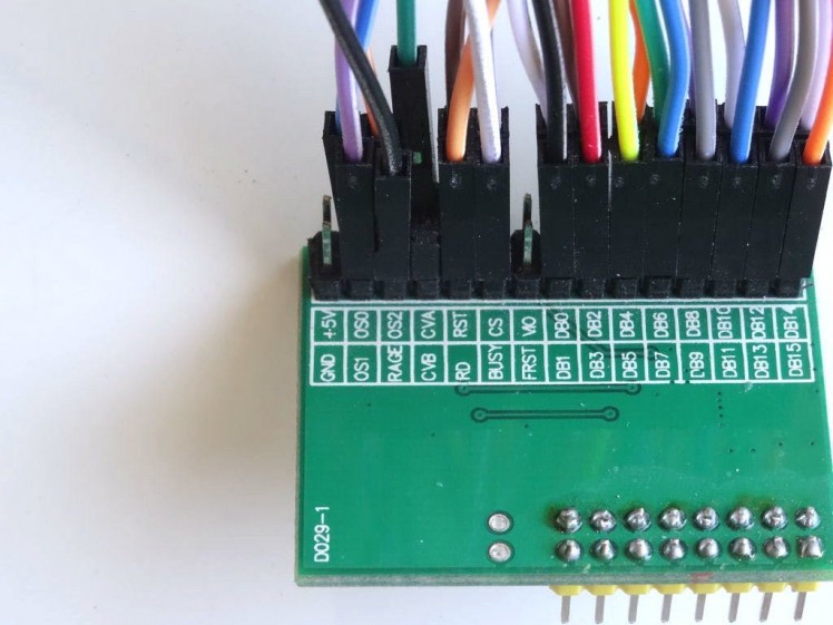
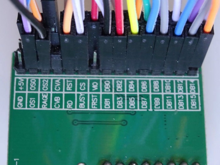
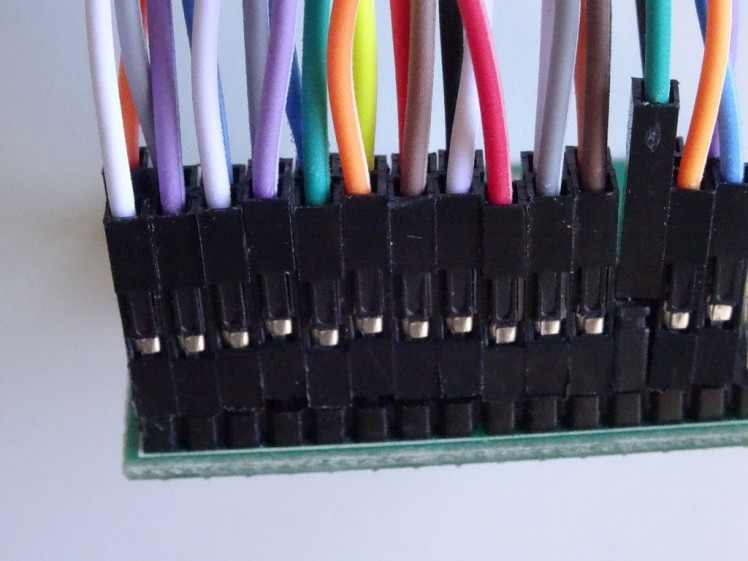
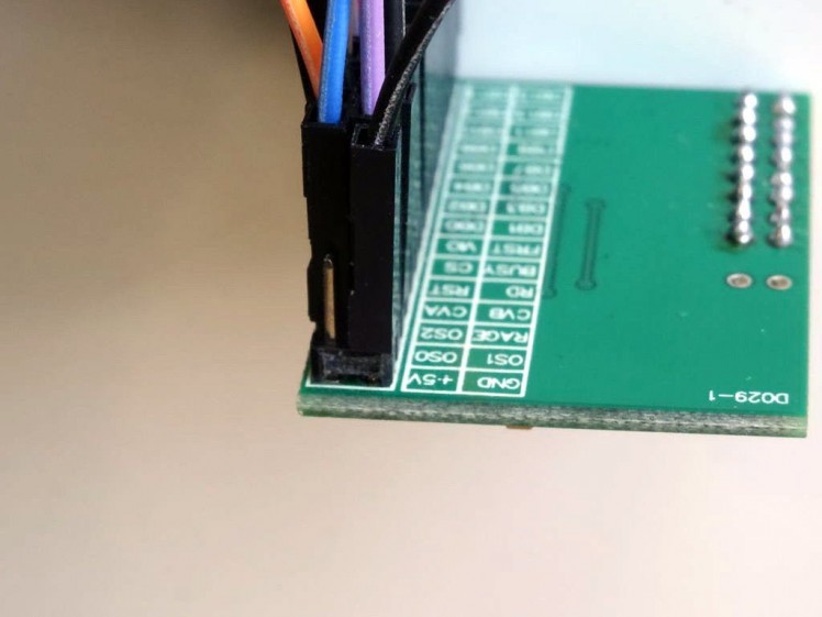
- Connect the Female end of a Female-Male(Black wire) to the RAGE pin of the AD7606 Module (Picture 1)
- Connect the Female end of a Female-Male(Red wire) to the VIO pin of the AD7606 Module (Picture 2 and 3)
- Connect the Female end of a Female-Male(Black wire) to the GND pin of the AD7606 Module (Picture 4)
- Connect the Female end of a Female-Male(Red wire) to the +5V pin of the AD7606 Module (Picture 5)
1 / 2 • Picture 1
Picture 1
Picture 2
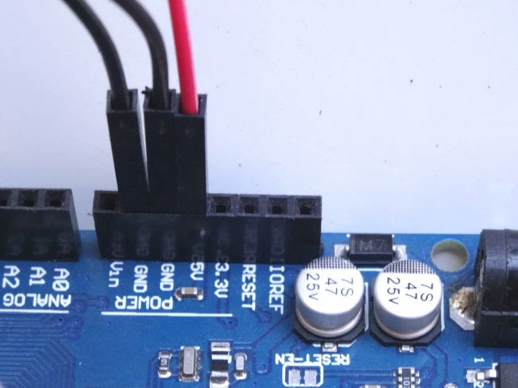
- Connect the Male ends of the Ground Wires(GND and RAGE) (Black wires) to the Ground pins of the Arduino Mega board (Picture 1)
- Connect the Male end of a Male-Male Power wire (Red wire) to the 5V Power pin of the Arduino Mega board (Picture 1)
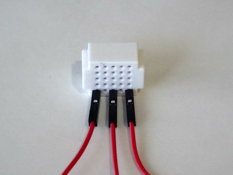
- Connect the Male ends of the 3 Power wires(Red wires) - the 2 wires(+5V and VIO) from the AD7606 Module, and the one from Arduino together as example with the help of a Breadboard (Picture 2) - In my case I used a small Breadboard
1 / 4 • Picture 1
Picture 1
Picture 2

Picture 3
Picture 4
To test the AD7606 Module we can use a Joystick. We will connect it to the first 2 Analog inputs, and will leave the rest unconnected. If you want, you can connect other analog signal sources to the rest of the channels.
- Connect Female-Female wires to the Ground(Black wire), Power(Red wire), VRx(Yellow wire), and VRy(Green wire) of the Joystick (Picture 1)
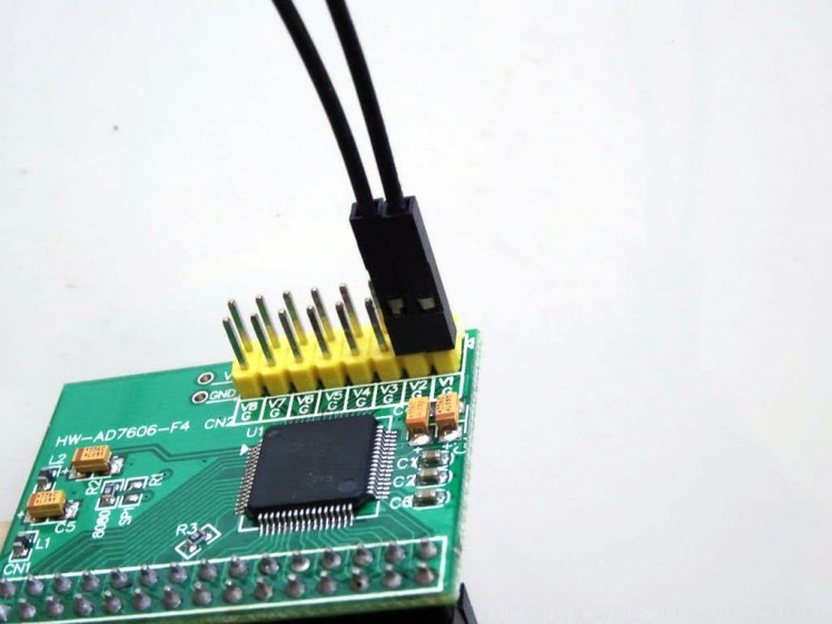
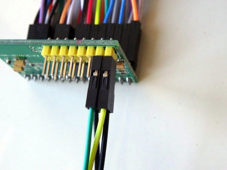
- Connect 2 Female-Female(Black wires) wires to the Ground pins of the first 2 Analog ChannelsV1 and V2 of the AD7606 Module (Picture 2 and 3)
- Connect the other end of the VRx wire(Yellow wire) to the Signal(Vx) pin of the first Analog Channel V1 of the AD7606 Module (Picture 4)
- Connect the other end of the VRy wire(Green wire) to the Signal(Vx) pin of the first Analog Channel V2 of the AD7606 Module (Picture 4)
1 / 4 • Picture 1
Picture 1
Picture 2
Picture 3
Picture 4
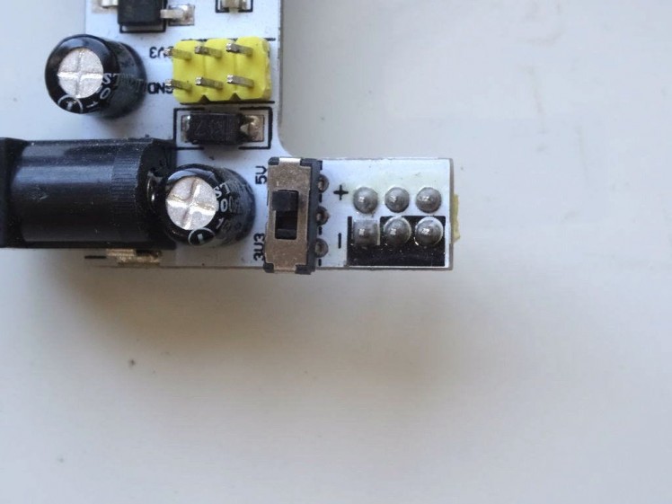
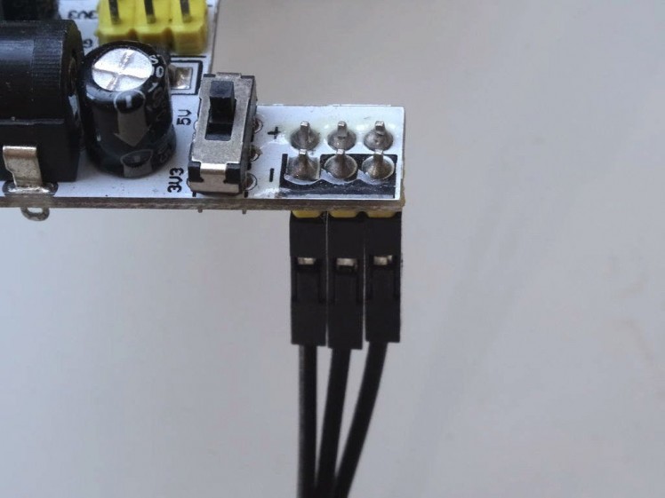
- Make sure the Power Selection Switch of the K2 power supply is set to 5V (Picture 1)
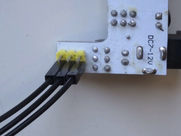
- Connect the other end of the 3 Ground wires (Black wires) from the Joystick and the AD7606 Module to the "-" Ground pins of the K2 Power supply (Pictures 2 and 3)
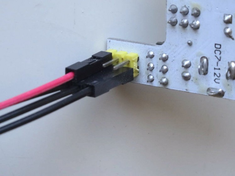
- Connect the other end of the Power wire (Red wire) from the Joystick to the "" Power pins of the K2 Power supply (Picture 4)
1 / 2 • Picture 1

Picture 1
Picture 2
To start programming the Arduino, you will need to have the Arduino IDE installed from here: http://www.arduino.cc/ .
Make sure that you install 1.6.7 higher, otherwise this Tutorial will not work!
The Visuino: https://www.visuino.com also needs to be installed.
- Start Visuino as shown in the first picture
- Click on the "Tools" button on the Arduino component (Picture 1) in Visuino
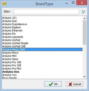
- When the dialog appears, select "Arduino Mega 2560" as shown in Picture 2
1 / 5 • Picture 1
Picture 1
Picture 2
Picture 3
Picture 4

Picture 5
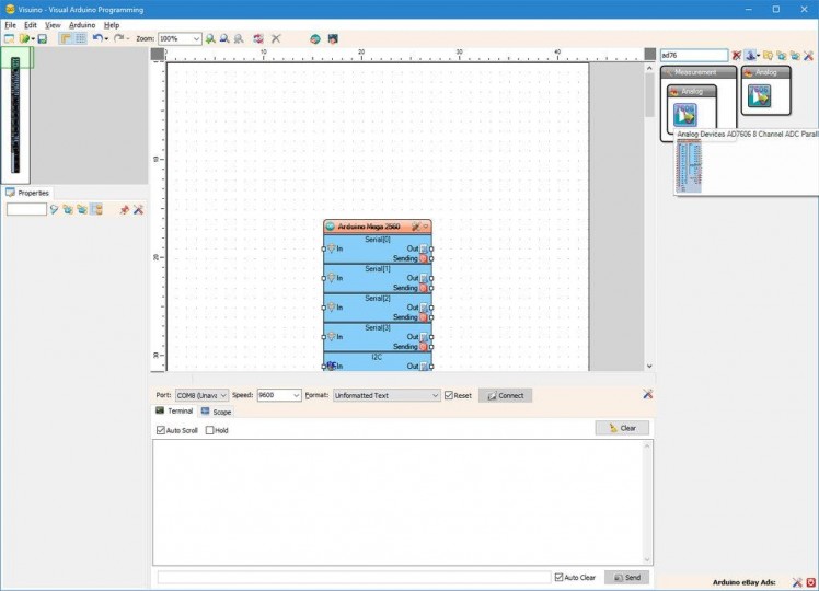
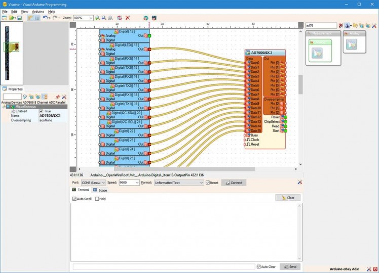
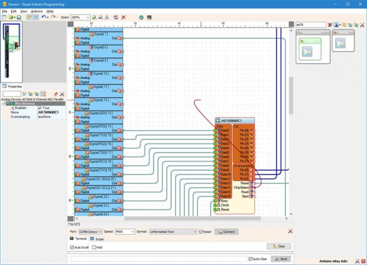
- Type "ad76" in the Filter box of the Component Toolbox then select the "Analog Devices AD7606 8 Channel ADC Parallel" component (Picture 1), and drop it in the design area (Picture 2)
- Click in the "Data" pins box of the AD7606ADC1 component to start connecting all the Data pins at once (Picture 2)
- Move the mouse over the "Out" output pin of the "Digital[ 13 ]" channel of the Arduino component. The Visuino will automatically spread the wires so they will connect correctly to the rest of the pins (Picture 2)
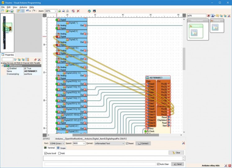
- Click in the "Oversampling" pins box of the AD7606ADC1 component to start connecting all the Oversampling pins at once (Picture 3)
- Move the mouse over the "Digital" input pin of the "Digital[ 8 ]" channel of the Arduino component. The Visuino will automatically spread the wires so they will connect correctly to the rest of the pins (Picture 3)
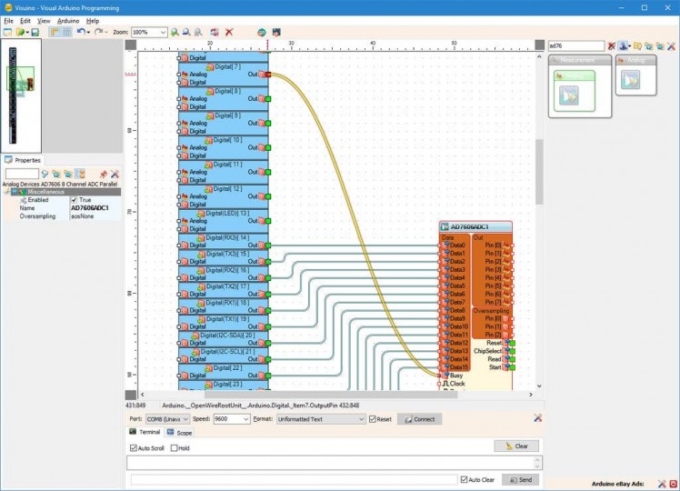
- Connect the "Busy" input pin of the AD7606ADC1 component to the "Out" output pin of the "Digital[ 7 ]" channel of the Arduino component (Picture 4)
- Connect the "Reset" Output pin of the AD7606ADC1 component to the "Digital" input pin of the "Digital[ 5 ]" channel of the Arduino component (Picture 5)
1 / 5 • Picture 1
Picture 1
Picture 2
Picture 3

Picture 4
Picture 5
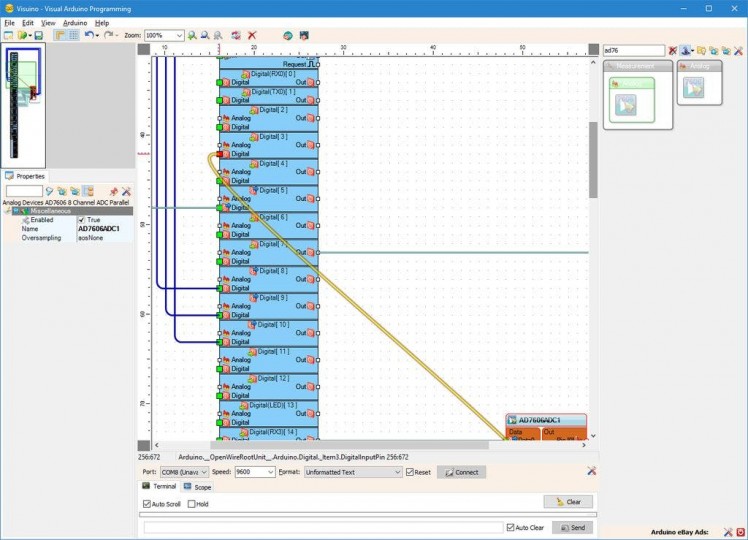
- Connect the "ChipSelect" Output pin of the AD7606ADC1 component (Picture 1) to the "Digital" input pin of the "Digital[ 3 ]" channel of the Arduino component (Picture 2)
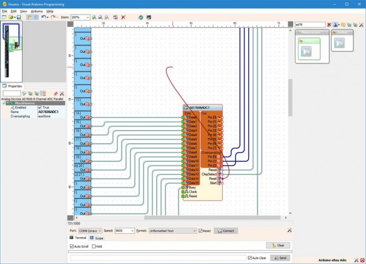
- Connect the "Read" Output pin of the AD7606ADC1 component (Picture 3) to the "Digital" input pin of the "Digital[ 2 ]" channel of the Arduino component (Picture 4)
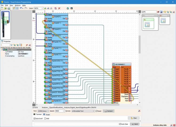
- Connect the "Start" Output pin of the AD7606ADC1 component to the "Digital" input pin of the "Digital[ 6 ]" channel of the Arduino component (Picture 5)
1 / 4 • Picture 1
Picture 1
Picture 2
Picture 3
Picture 4
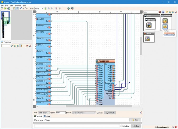
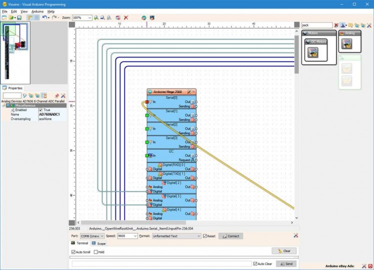
- Type "pack" in the Filter box of the Component Toolbox then select the "Packet" component (Picture 1), and drop it in the design area
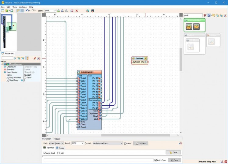
- Click on the "Tools" button of the Packet1 component (Picture 2)
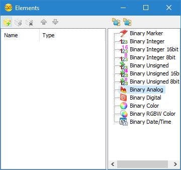
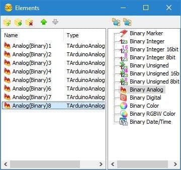
- In the "Elements" editor select the “Binary Analog” element, and then click 8 times on the "" button (Picture 3) to add 8 Analog elements (Picture 4)
- Close the "Elements" dialog
1 / 2 • Picture 1
Picture 1
Picture 2
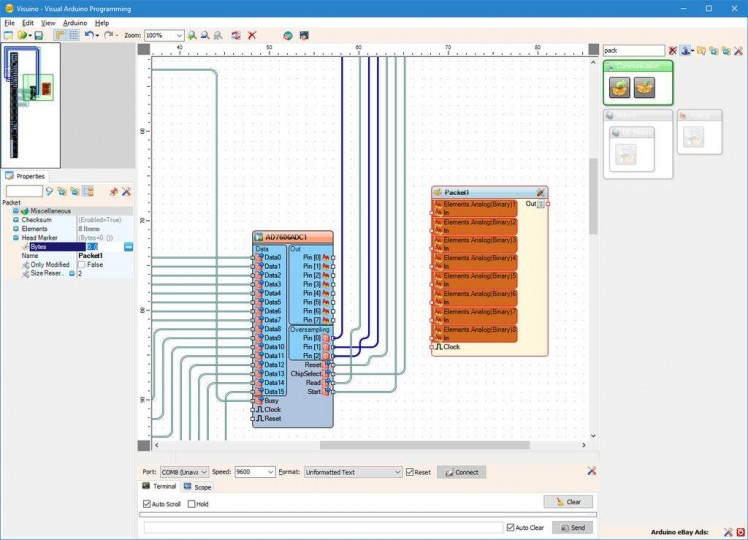
To make sure that Visuino will find the starting point of the packet, we need to have a unique header. The Packet component uses special algorithm to ensure that the header marker does not appear in the data.
- Select the Packet1 component (Picture 1)
- In the Object Inspector expand the "Head Marker"property (Picture 1)
- In the Object Inspector click on the "..." button (Picture 1)
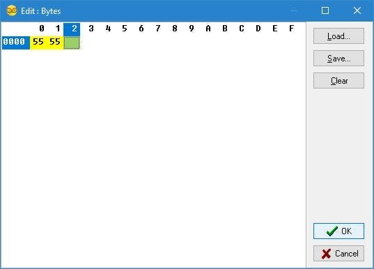
- In the Bytes editor type some numbers, as example 55 55 (Picture 2)
- Click on the OK button to confirm and close the editor
1 / 3 • Picture 1
Picture 1
Picture 2
Picture 3
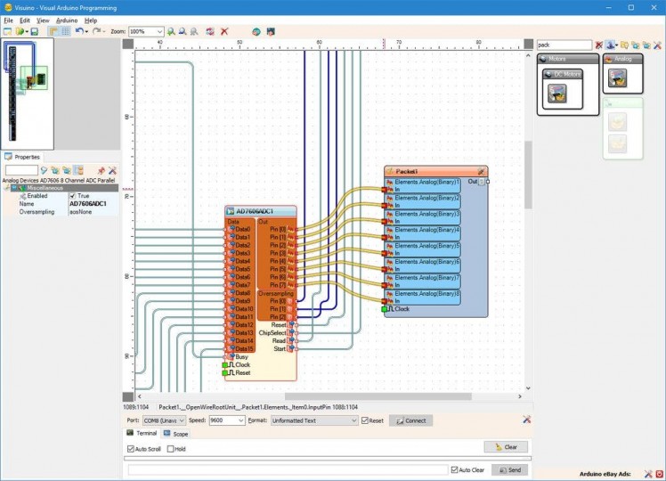
- Click in the "Out" pins box of the AD7606ADC1 component to start connecting all the Out pins at once (Picture 1)
- Move the mouse over the "In" input pin of the "Elements.Analog(Binary)1" channel of the Packet1 component. The Visuino will automatically spread the wires so they will connect correctly to the rest of the pins (Picture 1)
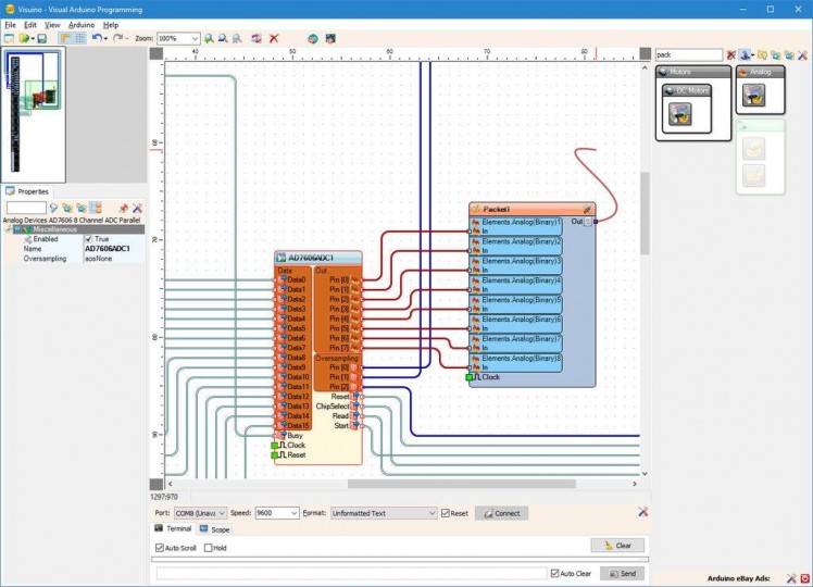
- Connect the "Out" output pin of the Packet1 component (Packet 2) to the "In" input pin of the "Serial[ 0 ]" channel of the "Arduino"component (Picture 3)
1 / 2 • Picture 1
Picture 1
Picture 2
- In Visuino, Press F9 or click on the button shown on Picture 1 to generate the Arduino code, and open the Arduino IDE
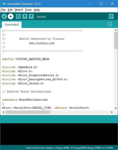
- In the Arduino IDE, click on the Upload button, to compile and upload the code (Picture 2)
1 / 5 • Picture 1
Picture 1
Picture 2
Picture 3
Picture 4
Picture 5
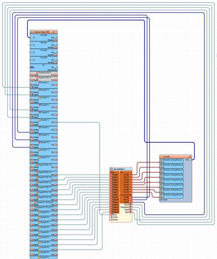
Congratulations! You have created an AD7606 8 Channel 16 bit Bipolar Analog to Digital Converter measuring project in Arduino, with Visual Instrumentation.
On Picture 1 you can see the complete Visuino diagram.
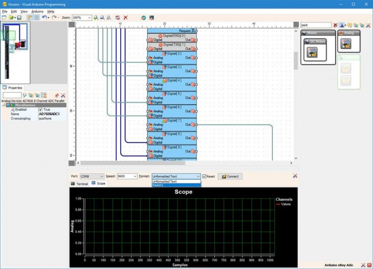
- In Visuino select the ComPort, and then click on the "Format:" drop down box, and select Packet1 (Picture 2)
- Click on the "Connect" button (Picture 2)
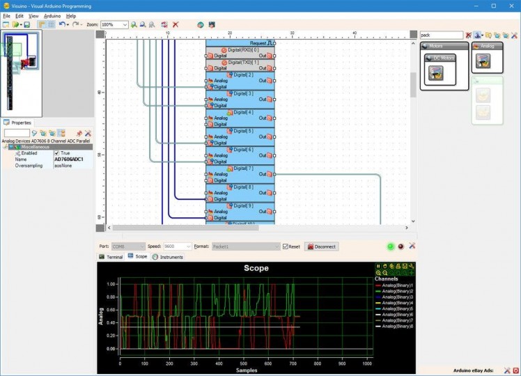
- If you select the "Scope" tab, you will see the the Scope plotting the values from the 8 Analog Channels over time (Picture 3)
- If you move the Joystick up and down, you will see the values of the first channel changing, and if you move it left and right you will see the values of the second channel changing. In the remaining 6 channels, you will see some small noise, as we did not connect any signal to them
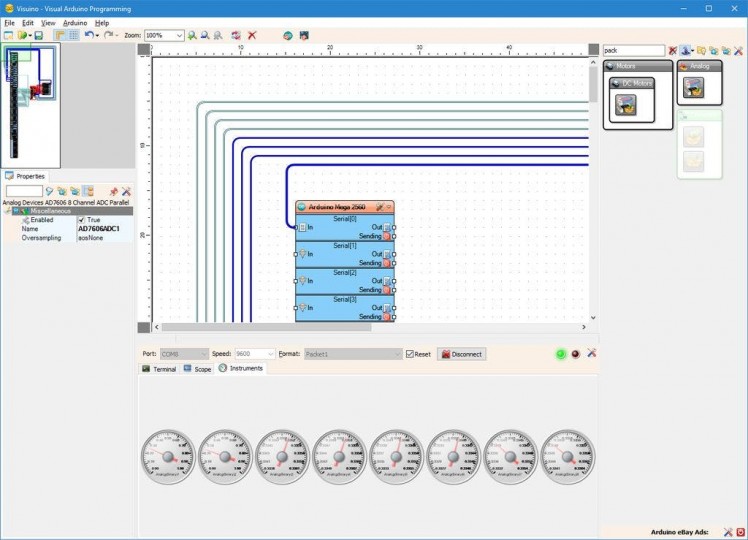
- If you select the "Instruments" tab, you will see the Gauges showing the same information (Picture 4)
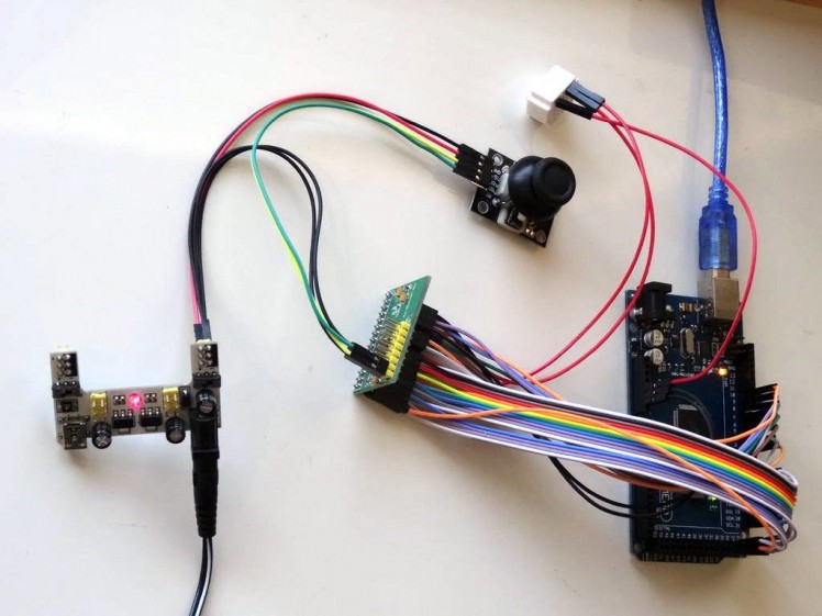
You can see the connected and running AD7606 8 Channel 16 bit Bipolar Analog to Digital Converter on Picture 5.
Also attached is the Visuino project, that I created for this tutorial. You can download and open it in Visuino: https://www.visuino.com




Leave your feedback...