Color Control For Rgbw Led Stripes
About the project
For using RGBW LED stripes properly, I was missing an easy control of color and brightness. Based on the PIC16F1827 I developed a control card using the serial line for communication and a Raspberry PI showing the Web based control page as part of my home control system.
Project info
Difficulty: Expert
Platforms: Microchip, Raspberry Pi
Estimated time: 1 week
License: GNU General Public License, version 3 or later (GPL3+)
Items used in this project
Hardware components
Software apps and online services
Story
When improving my home automation, I wanted to have also colored LED lighting. This seems to be easy but in reality I wanted to have an simple control of the color and I want to switch it on and off with a simple (local) switch. The last settings (color and brightness) before switching off should be kept. So that's where a micro controller comes into focus. In the following description I want to introduce you my ideas for your projects. Actually I tried to use a Microchip AVR-IoT with a simple setup, but I encountered several difficulties, so I decided to realize it based on my existing hardware and software setup.
For RGWB we need to control 4 lines individually, so one part is the electronic board, but the handling should also be easy and I did not want to fiddle around with 4 individual brightness controls.
So finally I came up with the idea to map the 4D colorspace into an 2D control as shown below:

Each corner is representing one color including the white LEDs. So using a knob I can easily select a color out of this color space. For brightness control I have one additional slider control and switch for turning it On / Off without the need to change the slider settings. This On/Off is same as a physical switch connected to the board.
Via a checkbox I can store this value as a new default setting in the flash memory of the micro controller. For information I can see the HEX values for RGWB brightness values.
For the hardware I used a PIC 16F1827 micro controller. Via commands over a serial connection I can set any RGWB value as well as default values (stored in the flash memory - e.g. used after power on)
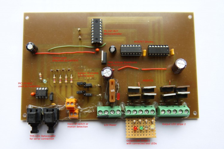
Finally my prototype looked like this:

In the following I give you a brief overview about the main topics.
For my home control web page I am using PHP on the PI and AngularJS for the controls.
The main issue was finding a function to map the 2D position to a 4D color map. The following code snippet shall explain the control shown above and the might help to implement a similar solution.
- /*
- * Calculates the color mixture for RGBW from the x/y Coordinates
- * @param x - 0-100
- * @param y - 0-100
- * @param scale - a scaling factor for brightness [0-255]
- * @result a color object including white
- * The corners are defined as:
- * 0/0 - green
- * 0/100 - red
- * 100/0 - blue
- * 100/100 - white
- */
- mixRGBW:function(x,y,scale)
- {
- if(!_gpf.isnumber(x)) {x=0;}
- if(!_gpf.isnumber(y)) {y=0;}
- if(!_gpf.isnumber(scale)) {scale=255;}
- var result={red:255,green:255,blue:255,white:255}; // Default-Antwort e.g. wenn alles gleich
- var s2=Math.sqrt(2);
- var s12=1/s2;
- if(x<0) {x=0} // check limits
- if(x>100) {x=100}
- if(y<0) {y=0}
- if(y>100) {y=100}
- x/=100; y/=100; // scale to 0-1
- var mx=1-x;
- var my=1-y;
- // calculate distance to diagonal line and scale
- var d1=(x-y);
- d1=Math.sqrt(d1*d1); // 0 - 1
- d1=(1-s12)*d1+s12; // scale to 1.0-1/sqrt(2) 1.0 if red/blue, 1/sqrt(2) if on diaginal line
- // calculate distance to red-blue diagonal line and scale
- var d2=(1-x-y);
- d2=Math.sqrt(d2*d2); // 0 - 1
- d2=(1-s12)*d2+s12; // aas above
- // calculate distance to corners
- var r=1-Math.sqrt(x*x+my*my)*d2;
- var g=1-Math.sqrt(x*x+y*y)*d1;
- var b=1-Math.sqrt(mx*mx+y*y)*d2;
- var w=1-Math.sqrt(mx*mx+my*my)*d1;
- // reduce influence to green and white to enable rot and blue
- g=Math.pow(g,2);
- w=Math.pow(w,8); // white shall increase slow in the corner
- // sacle maximum to 1
- var max=Math.max(r,g,b,w);
- r/=max;
- g/=max;
- b/=max;
- w/=max;
- // distribute white to RGB, so that with small white the colors are stronger and white alone only with w=1
- // => G(0)=0, G(0.62)=1, G(1)=0 => G=x*(1-x)*(x+0.25)*4
- var gw=w*(1-w)*4;
- r+=gw;
- g+=gw;
- b+=gw;
- w+=gw;
- // scale to 0-scale
- result.red=this.truncate(r*scale);
- result.green=this.truncate(g*scale);
- result.blue=this.truncate(b*scale);
- result.white=this.truncate(w*scale);
- return result;
- }
Some sub functions are not included but I think it is self explanatory.
The Raspberry PI
The PI is setup with Raspberian, Apache Web Server and PHP 7.
At start I initialize the serial device via:
- stty -F ttyS0 9600 raw -parenb cs8 -cstopb clocal -crtscts -ixon -ixoff -echo -echoe -echok -hup min 0 time 1 >/dev/null 2>&1 &
Then I can use the serial device via normal read/write from the Web site (PHP) or from any other code.
The Micro controller
The micro controller uses plain text serial communication (9600 baud to have max. compatibility). It can read, execute and answer simple commands.
For nerds like me, who want to try, I have attached the PCB top view and the hex file for programming the PIC16F1827.
The controller can communicate with following syntax:
ID.CMD[=value]
following characters are allowed: 0-9,A-Z,a-z,+,-,=,(,)
It is not case sensitive (lower case will be converted to upper case).
These are the commands:
- deviceid special command for reading the actual device ID (default = "ODEF")
- id.deviceid[=newID] - reads or sets a device ID
- id.out[1-2][=0-255] - read or set the brightness of one RGBW channel.This is done as PWM value with 61Hz - 0-off / 255-onThis value will be multiplied with the actual RGBW Color
- id.rgbw[1-2][=ffffffff] - reads or sets the actual color as HEX value
- id.default[1-2][=true] - reads or stores the actual brightness and color into the EEPROM. If true, it will be stored. The result is true when actual value and EEPROM value are identical
- id.in[1-4] - reads the digital inputs. 4 are possible but only 1 and 2 is used for RGBW channels
- id.switch[1-2] - if true the input will be used as switch, default is button
- id.switchpush[1-2] - if true the input will be used as button but triggered on rising edge, default=FALSE=switch
- id.disableWDT[=true|false] - disables the 256s watchdog timer, if no read or write access the output will be switched back to default. This will also be stored in the EEPROM - default true
A valid command will always be answered.
Summary
I hope this short summary gives you some ideas how to handle home automation DIY. Of course several improvements are possible, e.g. I have to update my control for touch screens.


Leave your feedback...