Build The Machine That Destroys What It Creates
About the project
Step-by-step guide to easily make your own super cool automated Kinetic Sand Art Coffee Table. Including smart LED lighting and integrated control panel.
Project info
Items used in this project
Story

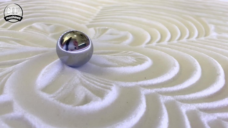
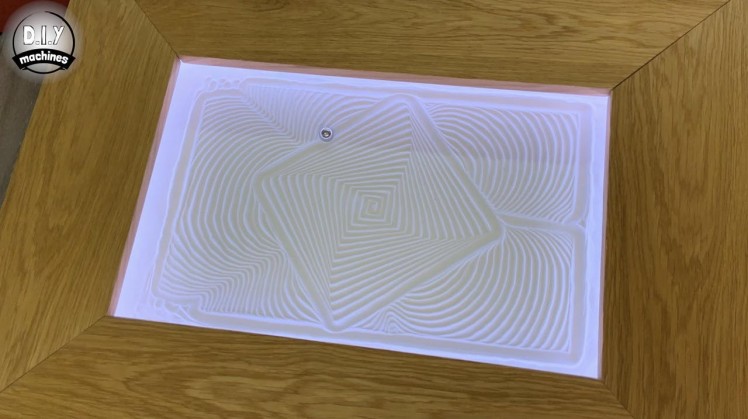
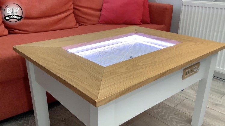
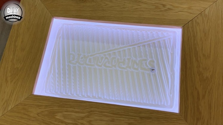
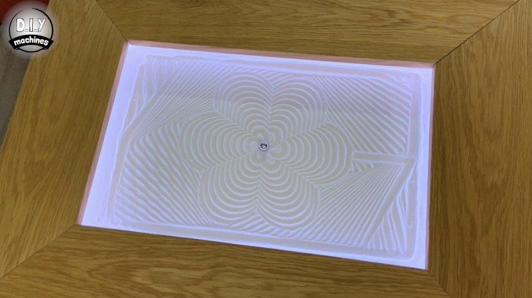
I’m going to show you exactly how you can easily make your own super cool automated kinetic sand art table step-by-step. Including smart LED lighting.
It is incredibly captivating to be beside this simple DIY wooden table as the steel ball magically carves out an endless and ever changing series of beautiful geometric patterns in the sand.
I was inspired to create this after coming across the idea by Sisyphus Industries: https://sisyphus-industries.com
My design is made from low cost pine, which is then painted in chalk paint. The top surface I also veneered with some European Oak. The mechanism that drives the steel ball around is a simple H-bot design and is controlled by an Arduino Uno and GRBL. An Arduino Nano is responsible for the smart LED lighting, and a Raspberry Pi takes command of playing our looping and ever changing list of patterns.
I also added some physical controls to the front so to allow easy and immediate access to features such as pausing and resuming the drawing, adjusting the LED brightness, speed and pattern.
I created a project video which shows you how to build one, but have also written this tutorial out as in certain areas it goes into more detail than the video and some tasks are just easier to follow in writing.
It's probably been the longest tutorial I've written out to date - there are 60+ steps and almost 400 images, but I have tried hard to ensure not to miss a single detail so you have every bit of information you need to successfully build one of your own.
None of the 3D printed parts for this project require any supports to be printed with the exception of the control panel. I worked hard when designing the 3D printable parts to eliminate the need for supports to save unnecessary printed plastic from needing recycling.
Step 1: Fusion 360 File and Wiring Diagram
1 / 5
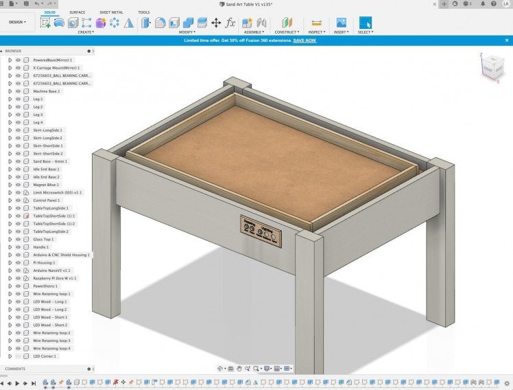
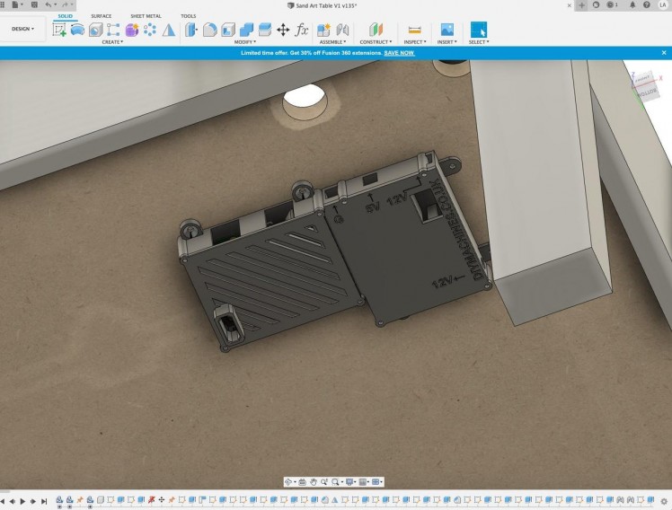
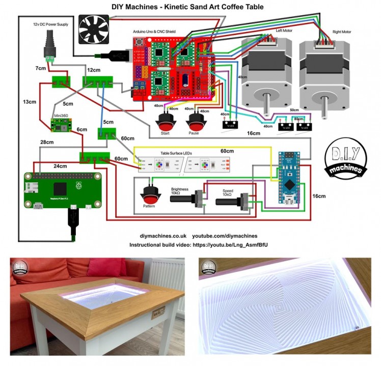
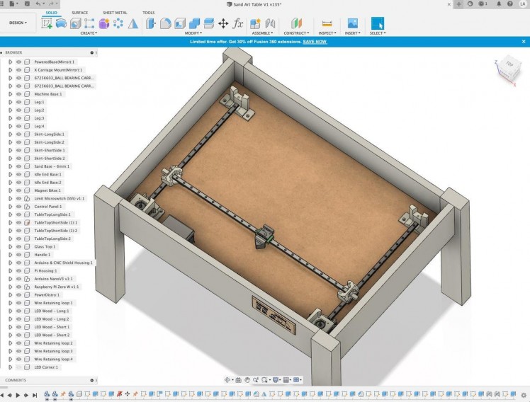
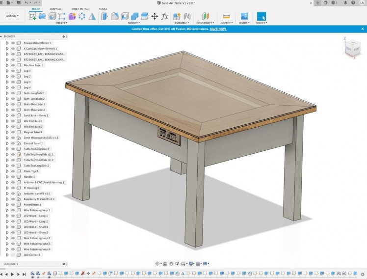
This is also the first time I have designed a project in Fusion 360. This means I can easily share the model with you to view in your browser. You can take a look at it here: https://a360.co/3eT8mr3
Please feel free to download it and make it your own. :)
I also created a wiring diagram for reference - though I will step you through it in detail throughout this guide.
Step 2: BOM (Bill of Materials)
1 / 2
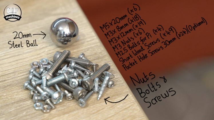

To build one of your own you will need a few things. Here is a list including links to where you can find them on Amazon:
- 12v Nema 17 stepper motors (x2): https://geni.us/StepperMotor
- GT2 Timing belt (3m was used in the video): https://geni.us/TimingBelt5m
- 5mm bore idler, 6mm or 10mm width, 20 teeth (x2): https://geni.us/6mmIdler5mmBoreToothed
- 5mm bore idler, 6 or 10mm width, toothless (x4): https://geni.us/6mmIdlerWheel5mmBore
- Elegoo Arduino Uno (x1): https://geni.us/ArduinoUno
- Nuts, bolts and screws (See list below): https://geni.us/NutsAndBolts
- M2.5 x 6mm bolts (for securing Raspberry Pi) (x4) - https://geni.us/PiBolt
- Stepper drivers - TMC2208 (x2): https://geni.us/TMC2208
- Contact switch (x3): https://geni.us/ContactSwitch
- Arduino CNC Shield (x1): https://geni.us/ArduinoCNCShield
- Magnets, I used three x 15x3mm and one countersunk 20x7mm all high strength: https://geni.us/CountersunkMagnet https://geni.us/N52Magnets
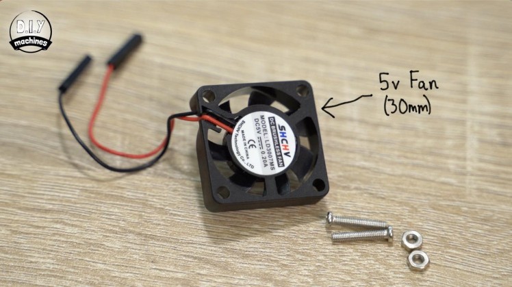
- 30mm 5V Fan (x1): https://geni.us/30mm5vFan
- Micro SD Card 8Gb or higher for Raspberry Pi (x1) - https://geni.us/Micro-SD
- Neopixels/WS2812b on a 30 per meter roll. - https://geni.us/5mWS2812B30m
- 12mm momentary push button (x3): https://geni.us/MomentaryPush12mm
- Some filament for the printed parts (I used PLA, including the wood infused lumberjack from 3D Jake) - https://www.3djake.com
- Wiring blocks - five wires (x2) and three wires (x2). I used the Wago 221 series - https://geni.us/Wago221
- Mini360 Buck Converter (x1): https://geni.us/Mini360
- Faux leather fabric (enough to cover the surface): https://geni.us/FauxLeather
- Arduino Nano (x1): https://geni.us/ArduinoNanoV3
- Electrical wire: https://geni.us/22AWGWire
- 12v power supply - 2A or greater (x1): https://geni.us/12VPowerSupply2A
- Barrel Connector - Female (x1): https://geni.us/FemalePowerBarrel
- Steel ball - 20mm
- Sand (I used around 600g):
To make a table frame which measures roughly 80 x 60cm:
- 40cm long linear rail with block - MGN12H (x2): https://geni.us/LinearRail400mm
- 60cm long linear rail with block - MGN12H (x1): https://geni.us/LinearRail600mm
See www.diymachine.co.uk for instructions on how to build a larger or smaller version.
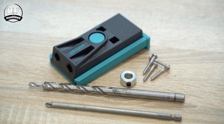
- Pocket hole jig: https://geni.us/PocketHoleJig
Nuts, bolts and screws needed:■ M5 x 20mm (x6) ■ M3 x 8mm (x18) ■ M3 x 12mm (x19) ■ M3 nuts (x6) ■ M2.5 bolts for Pi (x4) ■ Short wood screws (x45) ■ Optional pocket hole screws (x24)
Step 3: Cutting the First Parts for the Wooden Table Frame
1 / 5
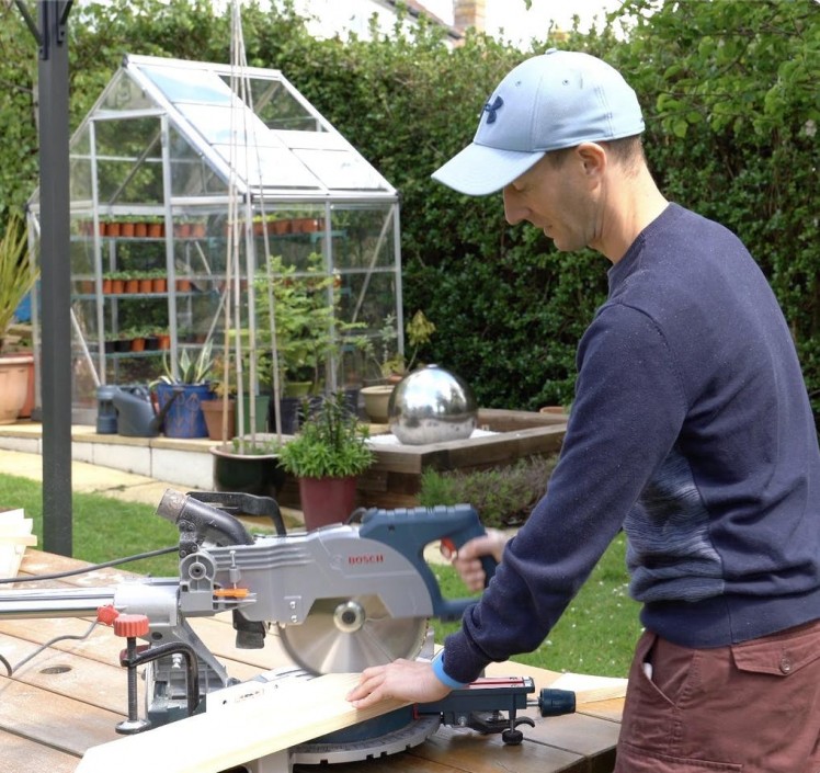
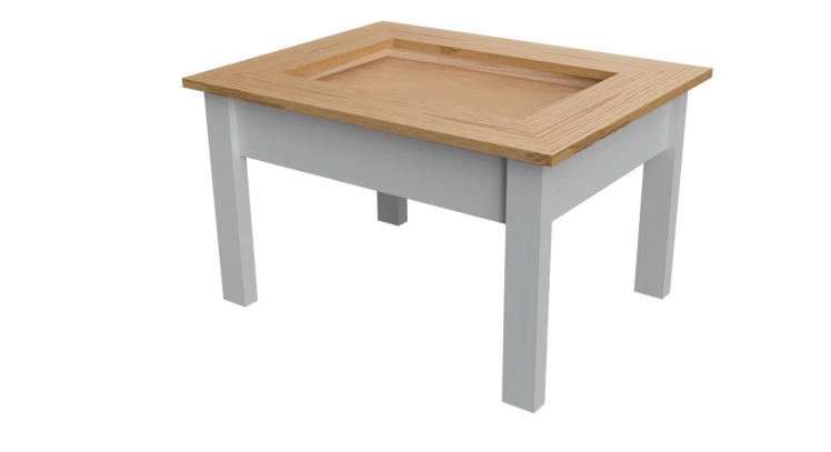
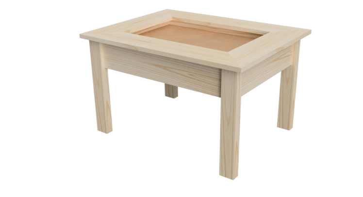
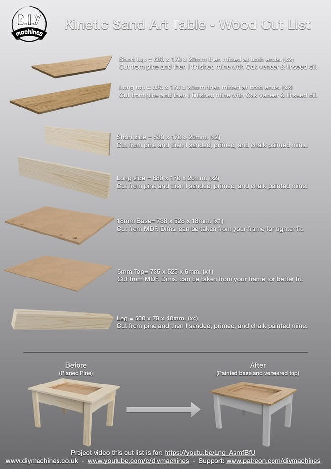

Let’s start by building the table frame so that we can fit our work as we go. The table frame I’m making is a very basic but effective design for which we need to cut just four different sizes of wood.
I built the frame from some low cost pine and some MDF I bought from the builders yard. It is not too expensive and is easy to work with. As I was going to finish all the visible wood with either paint or veneer the look of the wood was not too important.
I used a mitre saw to make my cuts.
You will need to cut several pieces before we can begin to assemble the frame to house our electronics. The handy sheet I have created and attached includes all the cut wooden parts for the entire project. Here are the parts we need for the next few steps:
- Short Side - Pine - 530mm x 170mm x 20mm. (x2)
- Long Side- Pine - 680mm x x170mm x 20mm (x2)
- Leg - Pine - 500mm x 70mm x 40mm (x4)
- 18mm Base - MDF - Roughly 738mm x 528mm x 18mm (x1) *
*The 18mm Base is best cut after assembling the four sides and taking measurements from your own table. The sizes I listed are what I cut mine after measuring the space inside of my frame.
Step 4: Adding a Cut Out
1 / 5
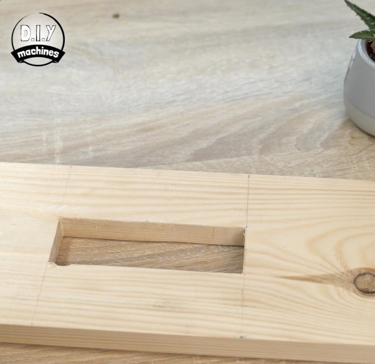
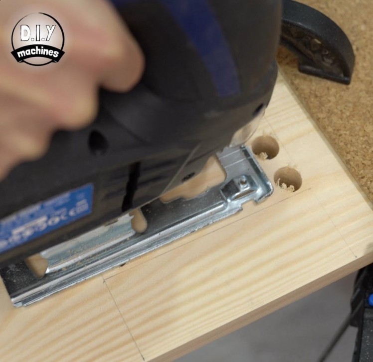
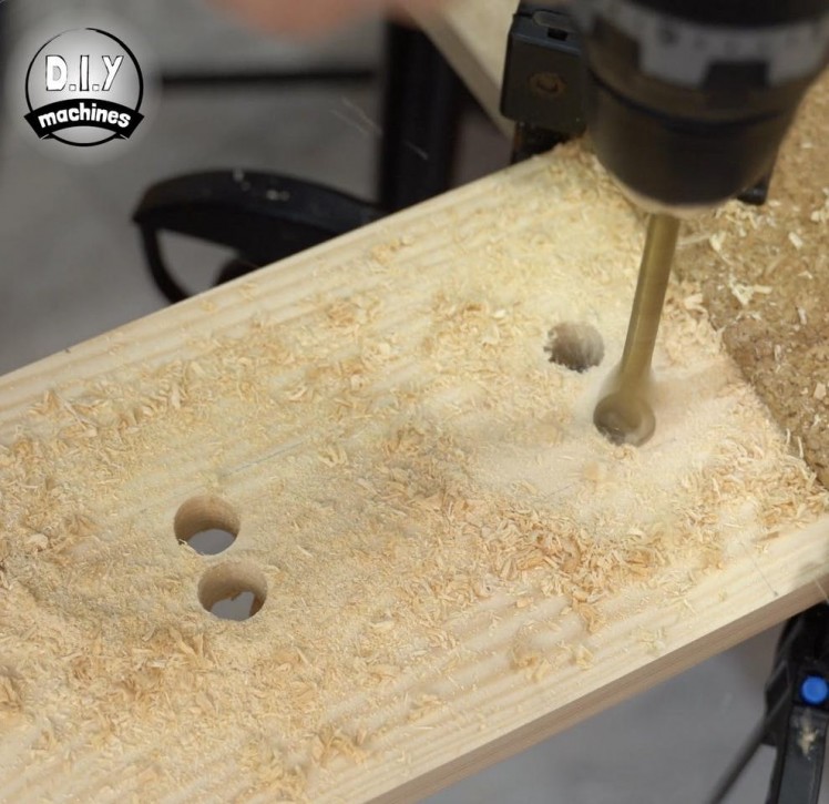
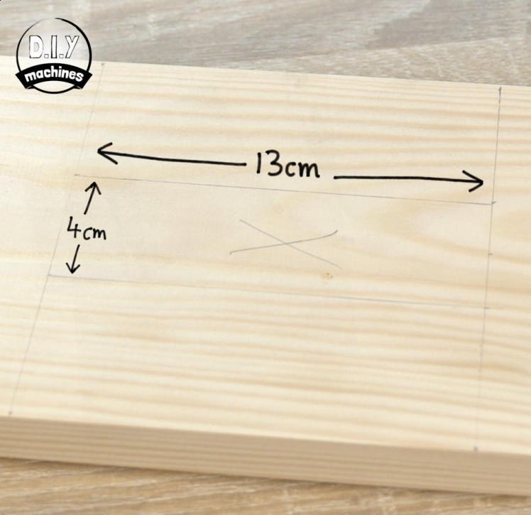
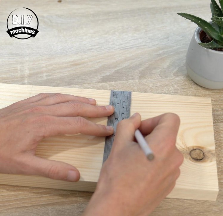
In one of our Long Side pieces we need to add a cut out which will house our control panel later in the build. It is easier to make this cut out now before assembling.
The cut out needs to be a rectangle about 13cm wide and 4cm tall centred vertically at one end of one of the long side panels. The control panels will sit in-front of it so it does not need to be a perfect cut-out.
I drew out the rectangle using a pencil and then made four holes inside of the four corners so that I could insert a jigsaw and make the cutout.
Step 5: Adding Pocket Holes
1 / 5
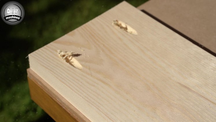
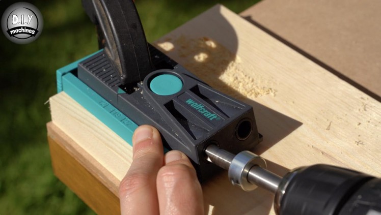
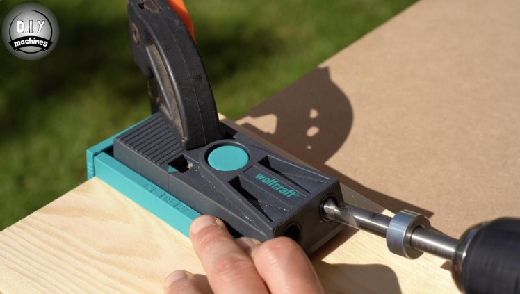
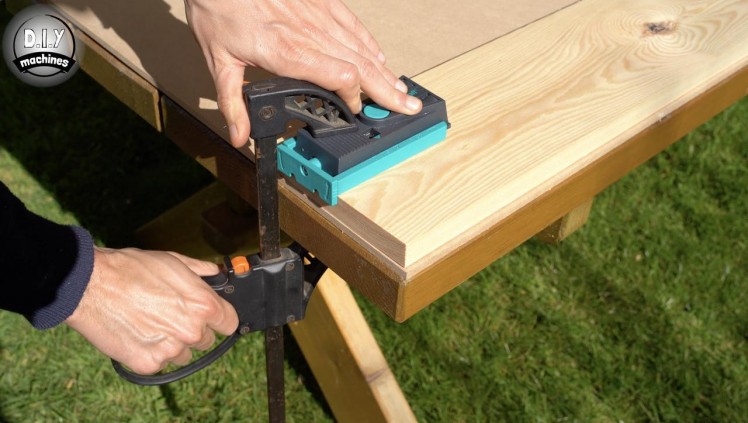
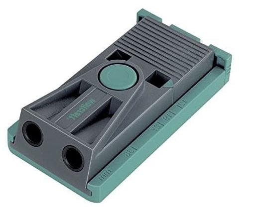
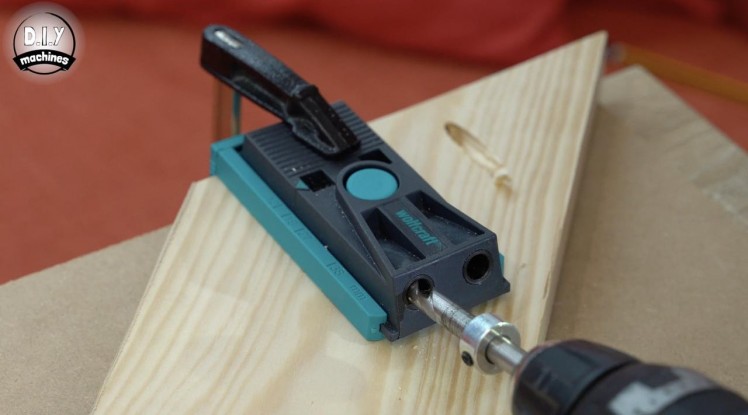
I decided to learn how to use pocket holes to assemble the frame of my table. They have several advantages, some of which are increased strength, rigidity, and being hidden from view. There is an excellent guide on pocket holes available in this video.
It's a little lengthy but I learned everything I needed to know from it so I wanted to share it with you. I used a simple pocket hole jig: https://geni.us/PocketHoleJig
After following the included manufacturers instructions on setting the correct position of the depth stop on the drill bit (the chunky disc screwed to the drill bit) based on the thickness of the wood, it is as simple as clamping it in place and drilling two holes in each end of the side four side pieces. Their spacing does not need to be precise, just not too near the edges and far enough apart from each other to have an extended grip on the adjoining piece of wood later.
Don't forget to have a look at both sides of the wood panels and choose which side would be better facing outwards. We want to drill our pocket holes into the rougher of the two sides as this will be the side hidden from view.
Step 6: Attaching Legs to the Long Side Panels
1 / 4
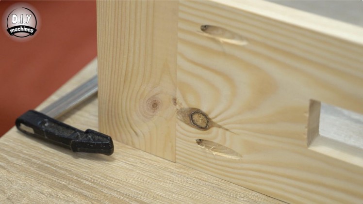
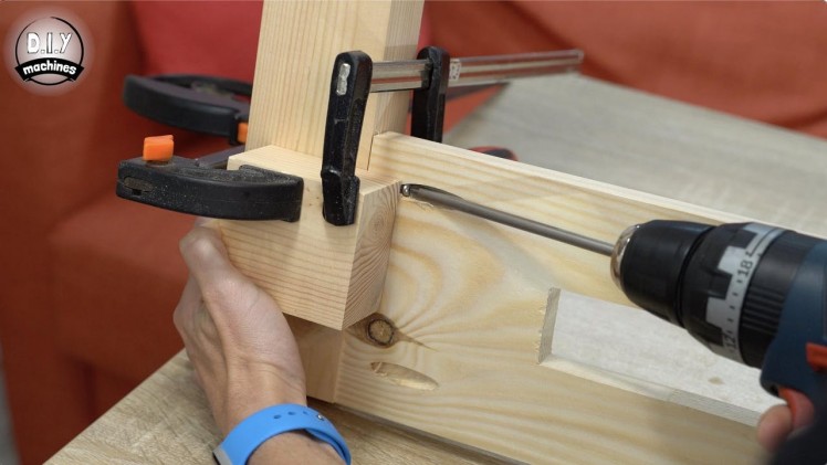
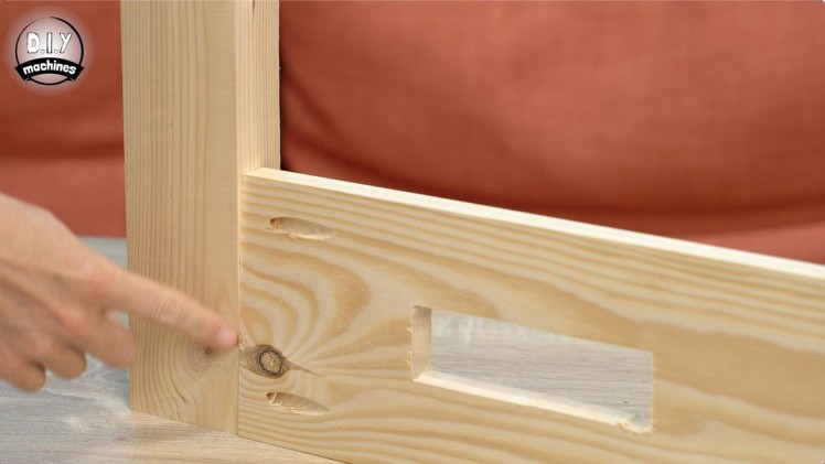
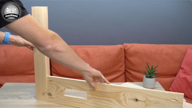
For this step you will need:
- Pocket hole screws (x8)
- Some clamps
- Screwdriver
After the pocket holes are drilled we can begin by attaching the long sides to the legs.
Take one long side and one of the legs. The face of the wood with the pocket holes should be fitted flush with the wider face of the leg. (Take a look at the above photos for additional clarity).
I used some offcuts of wood and clamps to hold the two face flush whilst screwing in a pocket screw through each of the two holes we made with the jig earlier. Repeat this for the other end of the Long Side panel.
Repeat this all again for the other Long side panel and two remaining legs.
Step 7: Add in the Short Side Panels
1 / 5
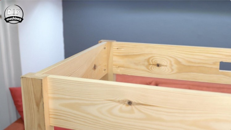
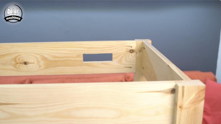
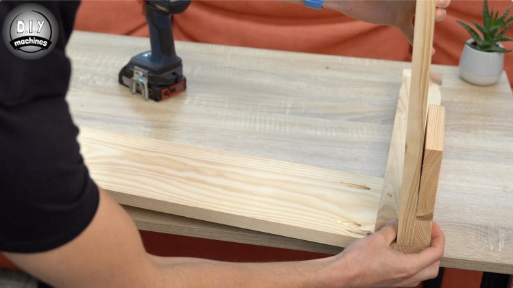
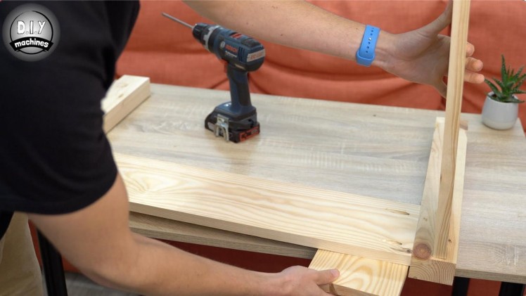
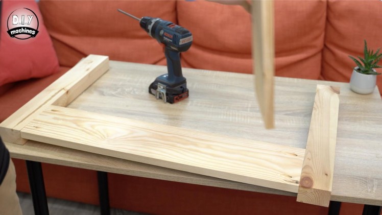
For this step you will need:
- Pocket hole screws (x8)
- Screwdriver
- Clamps
Once the two long sides are attached to the legs we can use the two short side panels to connect everything up together.
Place one of the assembled long sides onto your work surface with the pocket holes facing upwards. I positioned the short sides inset from the front by the same distance the long side panels are. I used a block of wood to ensure both are the same distance. (2nd and 3rd images). Don't forget to ensure the pocket holes are facing towards the inside of the table frame.
Use some clamps to hold it firmly in place and then affix with the pocket hole screws. Repeat this at the other end for the already assembled long side before bringing the remaining pieces together and fastening with pocket hole screws.
Step 8: Fit the Baseboard
1 / 7
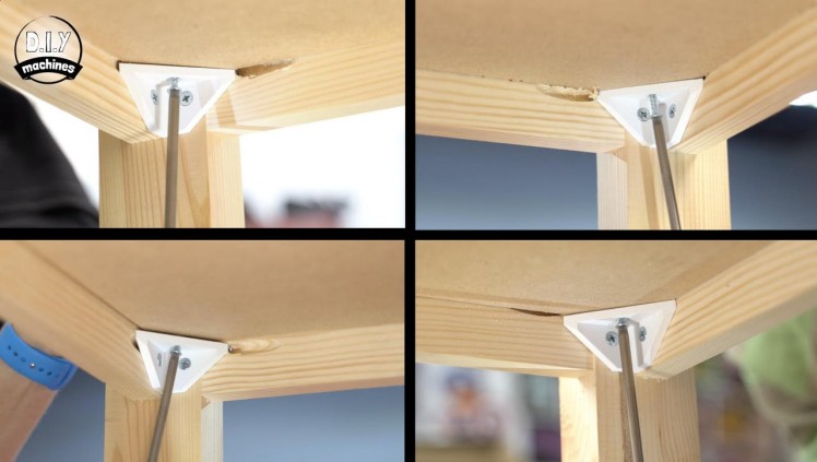
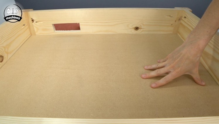
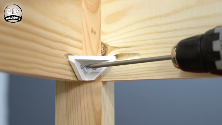
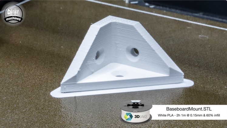
For this step you will need:
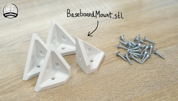
- BaseBoardMount.stl (x4 - There are two in each print)
- Short wood screws (x12)
- 18mm MDF board
- Screwdriver
- Tape measure / ruler
You will need our first 3D printed parts now, which is four of the BaseSupports. I have printed everything for this project with PLA plastic using a 50% infill. You will find the model data for the prints attached to each step where they are required.
Whilst they print we can cut the 18mm baseboard to fit within the frame. It's easiest to do this by flipping the table upside down on top of your MDF sheet and use a pencil to draw around the inside of the table. You can then cut this out and check it for fit.
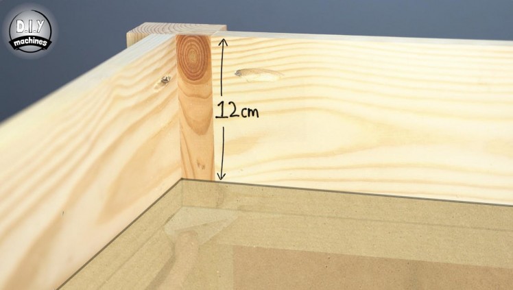
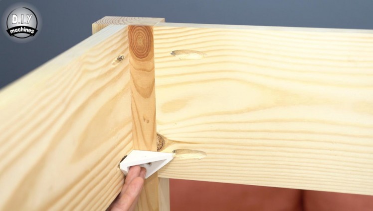
To secure it at the correct height inside of the table, position the brackets in the corners so that once the baseboard is added on top, the boards surface will be about 12cm from the very top of the table. Screw the supports in place followed by the baseboard from beneath with some more wood screws.
Step 9: Paint the Table Frame
1 / 9
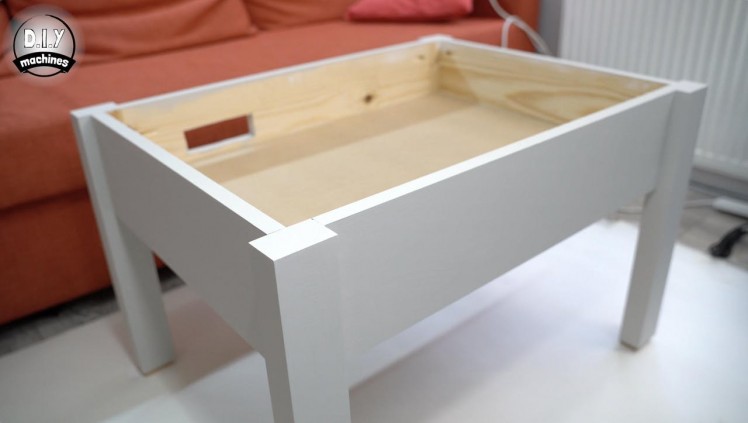
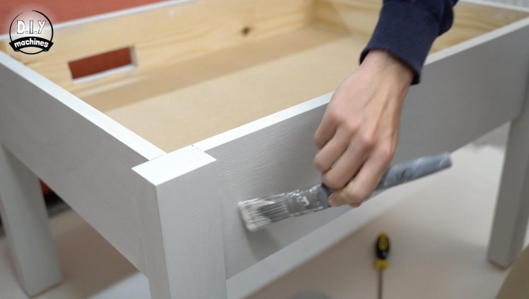
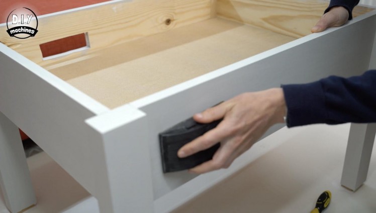
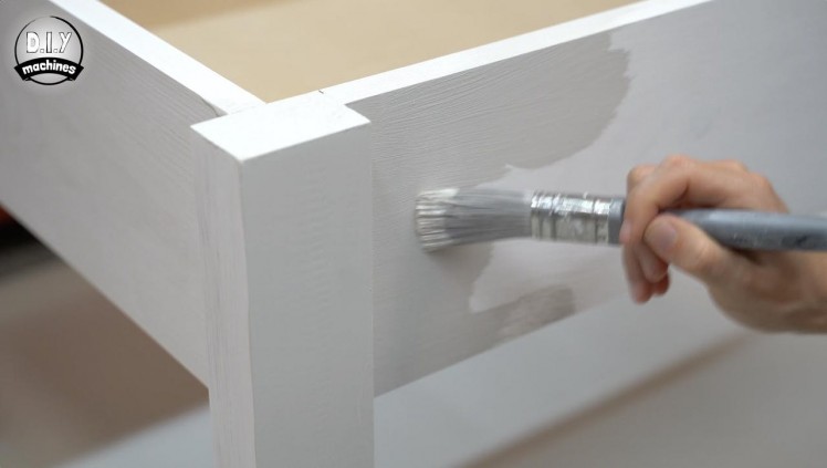
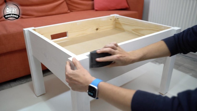
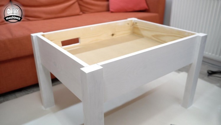
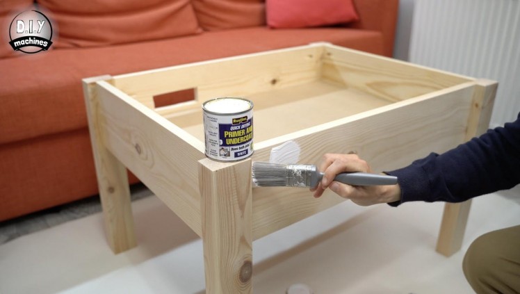
For this step you will need:
- Primer
- Finishing paint of your choice
- Paintbrush
- Sandpaper
To finish my table frame I chose to paint it with some light grey chalk paint.
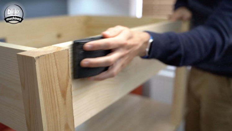
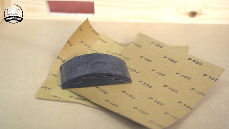
As with all jobs well done, it comes down to some good preparation. This involved sanding the table with a coarse grit and then progressively finer grits. I chose to start at 180 grit, followed by 240 and then 400.
Once this is done, and you have removed the dust from the area and table we can seal the wood with some primer. I applied one coat of primer, let it dry fully and then 'de-nibbed' it by lightly running over it with some 400 grit sand paper. This helps to remove any raised lumps and bumps before we apply the next coat to the table. Without this the imperfections would build up with each coat.
I then applied a coat of chalk paint, de-nibbed it after letting it dry and finally applied a second coat of chalk paint.
Step 10: Preparing the Motors
1 / 3
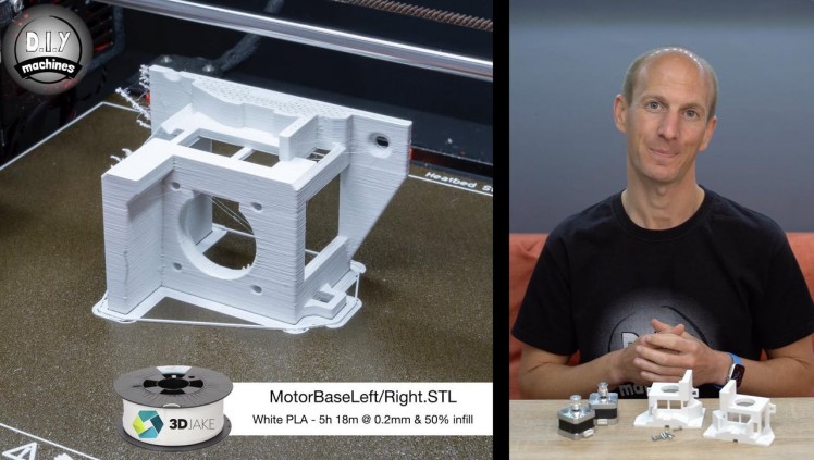
For this step you will need:
Printed parts:
- MotorBaseLeft.stl
- MotorBaseRight.stl
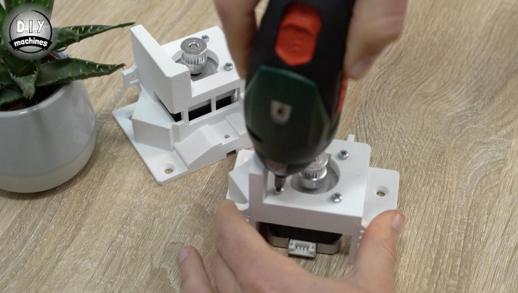
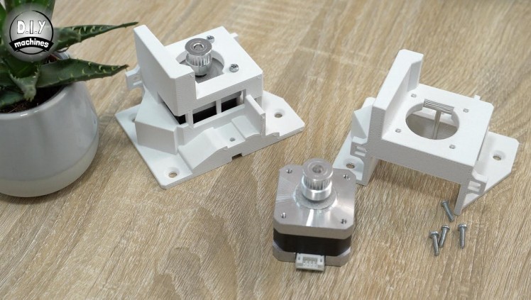
Let’s start working on the electronics by first printing two parts, the left and right hand motor mounts. Again, I printed mine in PLA with a high infill percentage (50%) for additional strength.
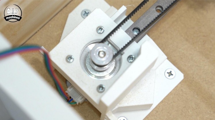
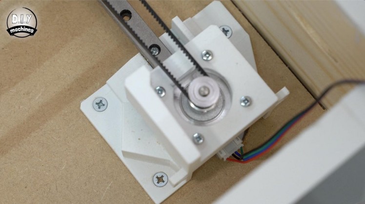
To these, we can add the two stepper motors using four M3 x 12 bolts to secure each one. Ensure that the power cable is exiting from the rear. The timing belt pulley wheels can also be added so that the top is flush with the tip of the shaft and though both grub screws should be tightened firmly, at least one of the grub screws should be tightened against the flat part of the shaft.
Step 11: Assembling the Gantry System - P1
1 / 10
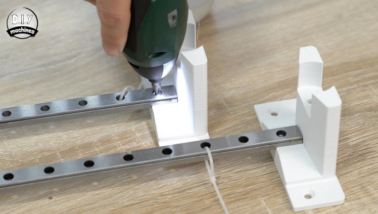
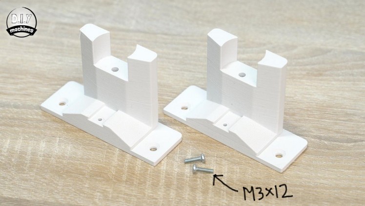
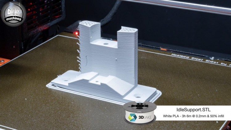
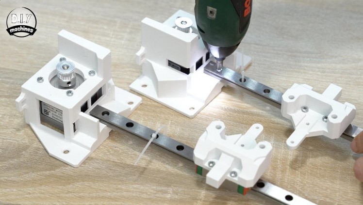
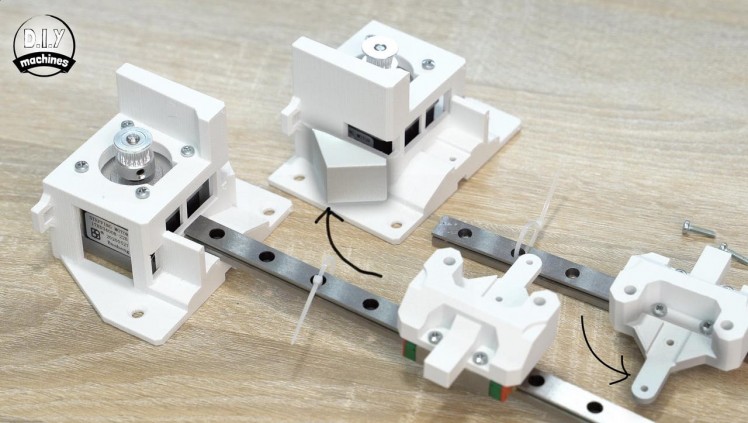
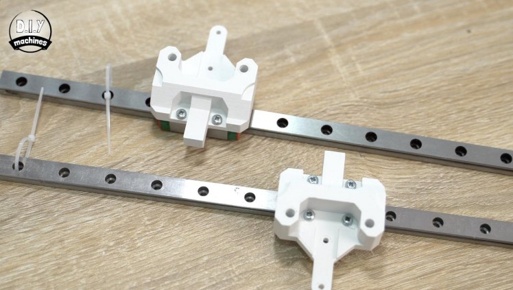
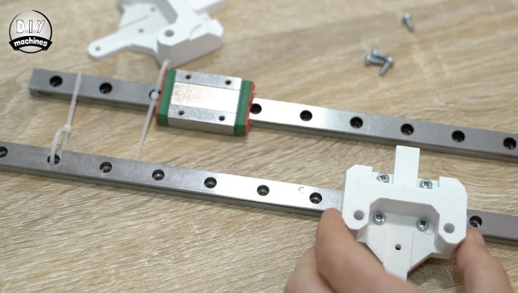
For this step you will need:
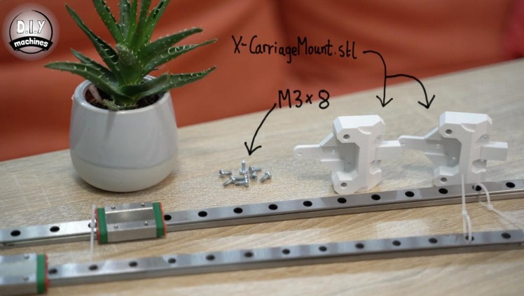
3d Printed parts:
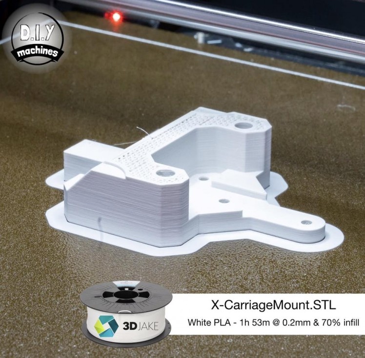
- X-CarriageMount.stl (x2)
- IdleMount.stl(x2)
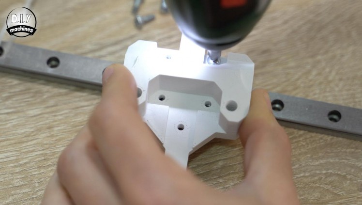
Our 3D printed X carriage mounts can be attached to the ends of the two shorter linear rails. Use M3x8 bolts to attach these firmly to the blocks.
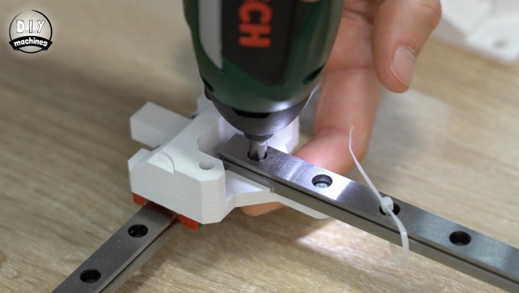
Going back to the motor mounts, we can now attach one motor mount to one end of a rail with a M3x12 bolt, and then do the same for the other pair. The arrow like side of each motor mount (highlighted in the 6th image) should be on the same side as the long narrow protrusion of the x carriage on the linear rail.
Print two idler mounts and fit these to the other ends of the rails using M3x12 bolts
Step 12: Assembling the Gantry System - P2
1 / 4
For this step you will need:
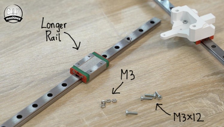
- 60cm MGN12H Linear Rails (x1)
- M3x12 bolts (x4)
- M3 nuts (x4)
- Screwdriver
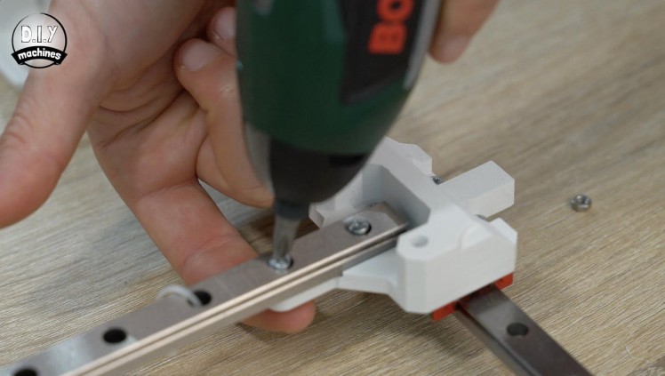
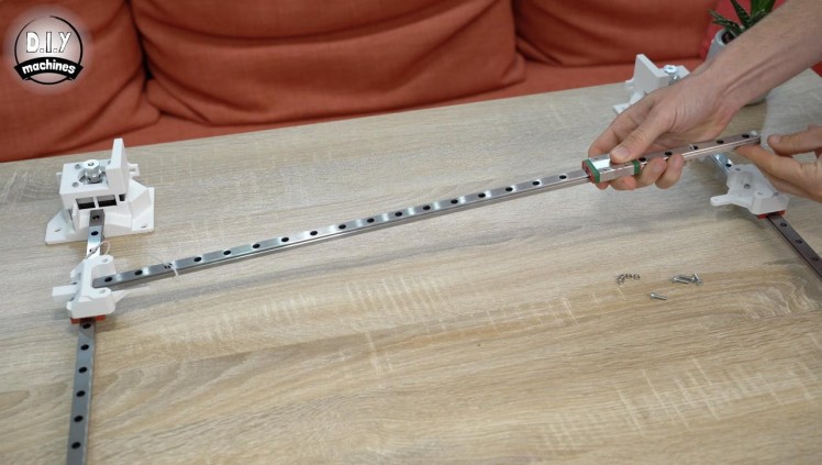
The remaining linear rail can then be fitted spanning the gap between the first two rails. Fit this in place using a pair of M3x12 bolts with nuts at both ends to hold it firmly.
Step 13: Fitting Gantry to the Table Frame
1 / 8
For this step you will need:
- Short wood screws (x10)
- Screwdriver
- Drill and drill bits
- Ruler / tape measure
- Pencil
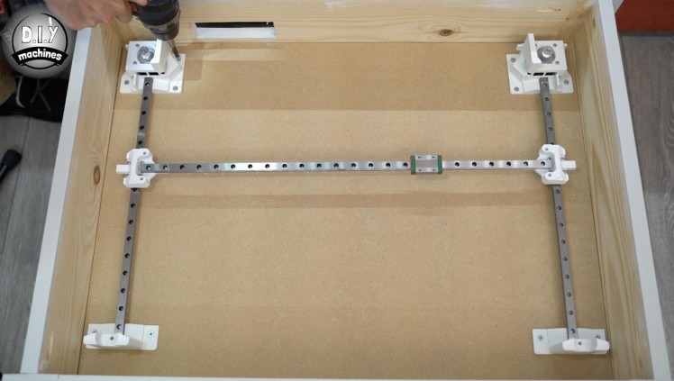
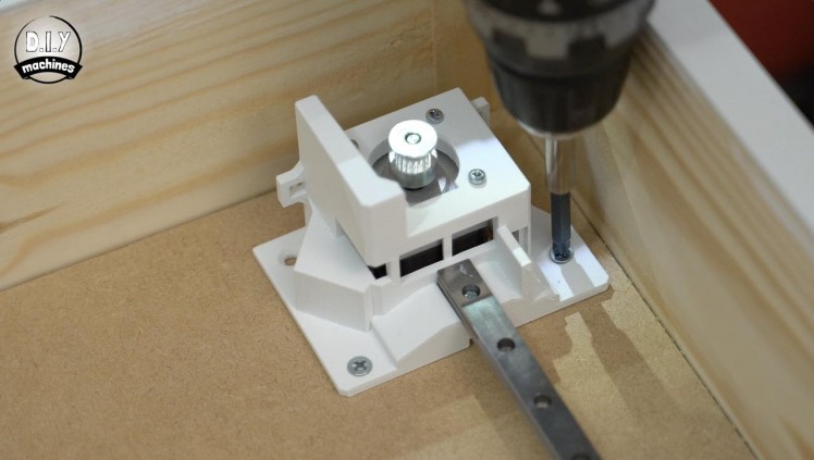
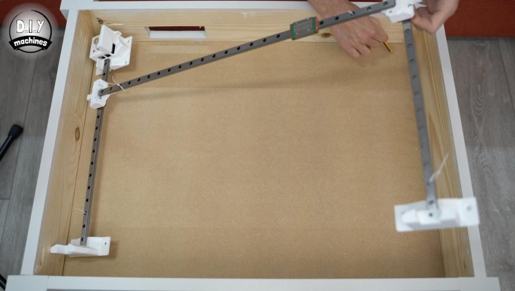
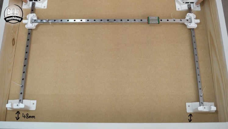
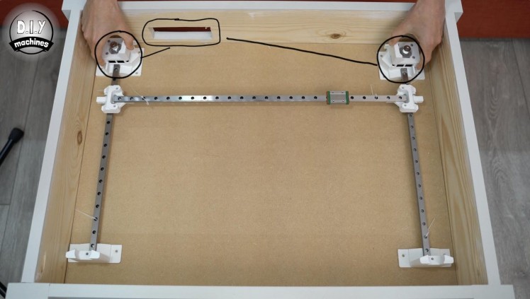
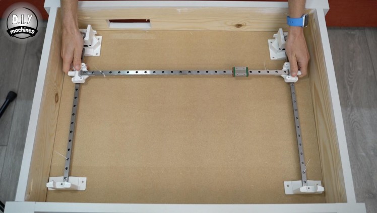
We can then take this to our table frame and position it on the baseboard. It should be centred width ways, with the motors on the side of the cutout and the printed idle ends should be about 48mm inwards from the edge of the table.
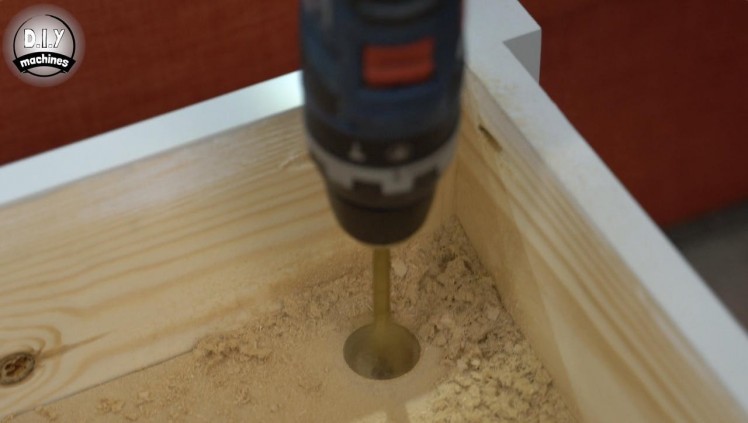
Mark roughly where the centre of the motors are, remove the rails and electronics and use a drill or similar to make a cutout about 3cm in diameter under both motors. This will help to keep the stepper motors cool with the fan we will add later, quietly bringing fresh air in through these inlets and around the motors.
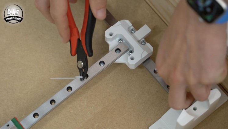
Reposition the carriage, remove any cable tidies or plugs securing the blocks to the rails, and then secure to the baseboard using your wood screws. Slide the carriage back and fourth and use a ruler to continually measure as you do this so that you can be sure the base is not skewed and that the mechanism runs freely without restriction.
Step 14: Attaching the Magnet Mount
1 / 4
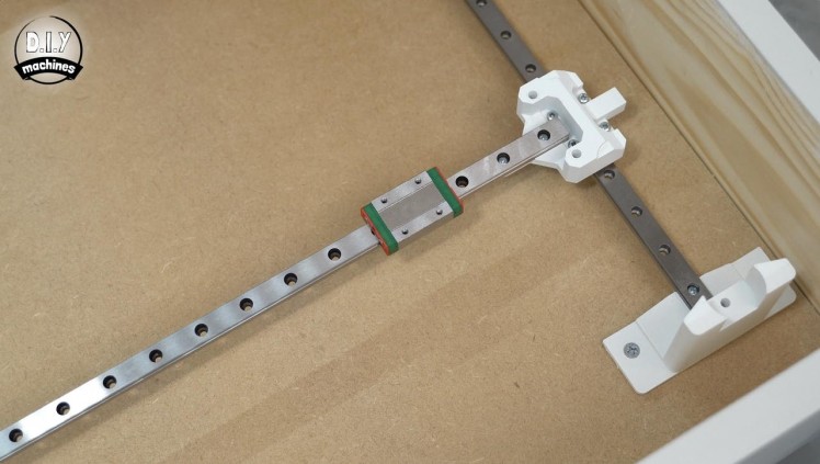
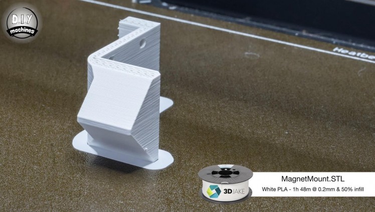
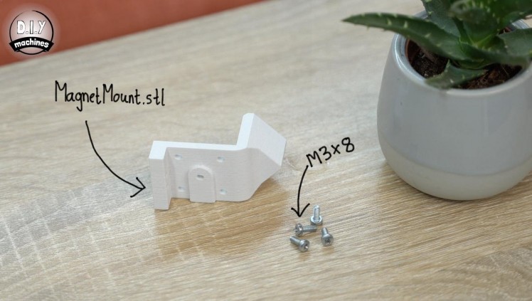
For this step you will need:
3D prints:
- MagnetMount.stl (x1)
- M3x8 bolts (x4)
- Screwdriver
Next print the Magnet Mount.
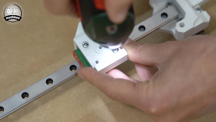
This can then be attached to sliding block on the longest linear rail (on our X carriage - the one which runs side to side) using four M3 x 8 bolts. We will be attaching our magnets and timing belt to this later.
Step 15: Installing the Idler Wheels
1 / 6
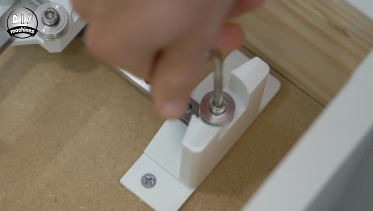
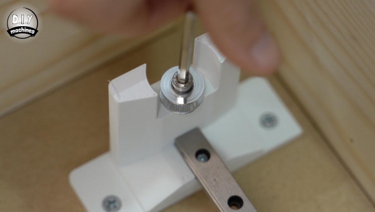
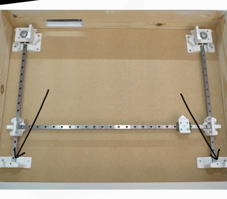
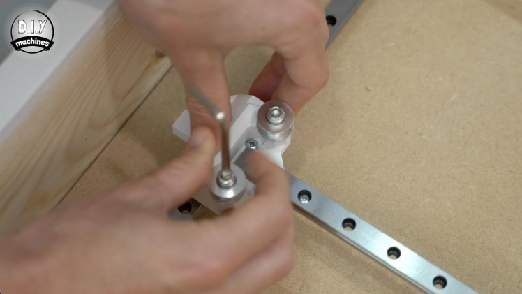
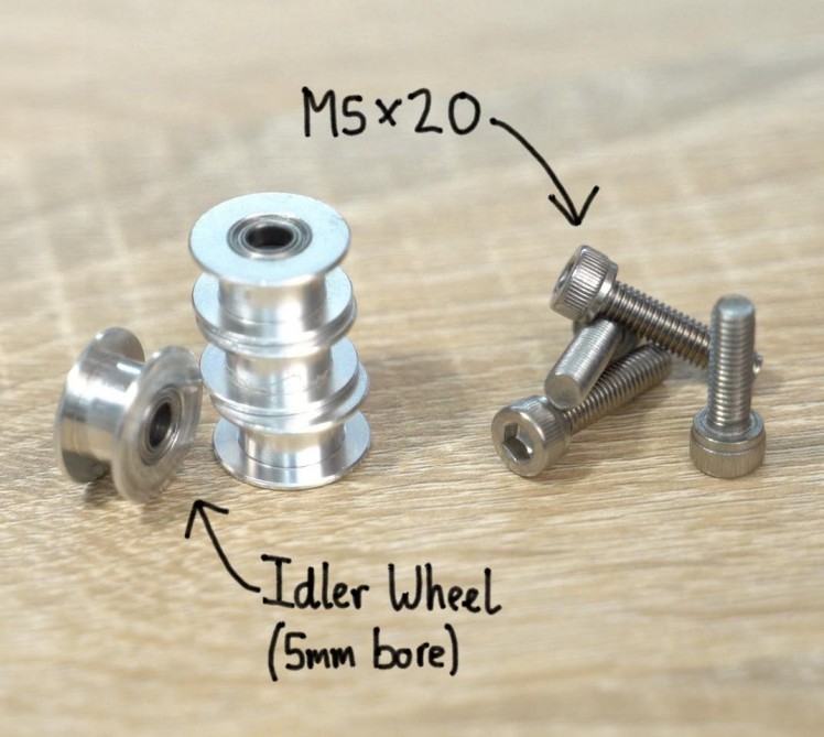
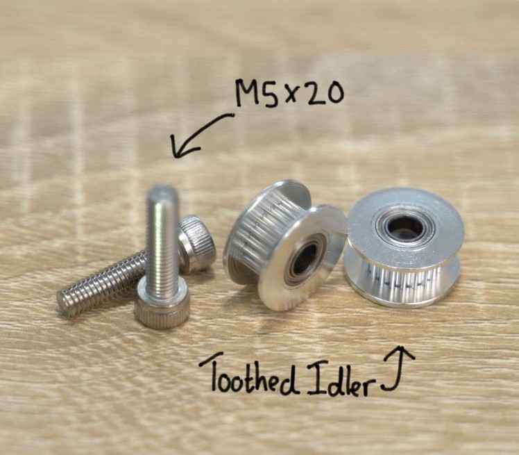
For this step you will need:
- M5x20mm bolts (x6)
- 5mm bore idler, 6 or 10mm wide, with teeth (x2)
- 5mm bore idler, 6 or 10mm wide, toothless (x4)
Install the four toothless idlers on the ends of the long X axis using the M5 bolts without over tightening them. The wheels should still be able to turn freely when spun with your finger.
The two toothed idlers should be fitted on top of the printed idler mounts in the same fashion.
Step 16: Installing the Timing Belt
1 / 11
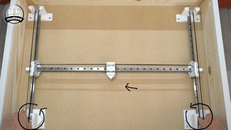
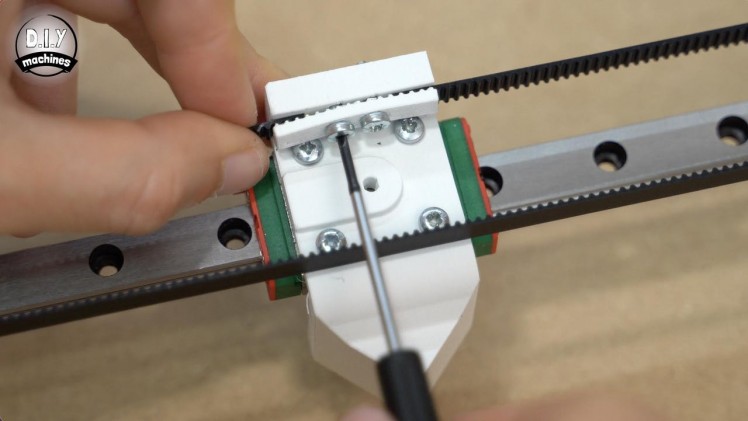
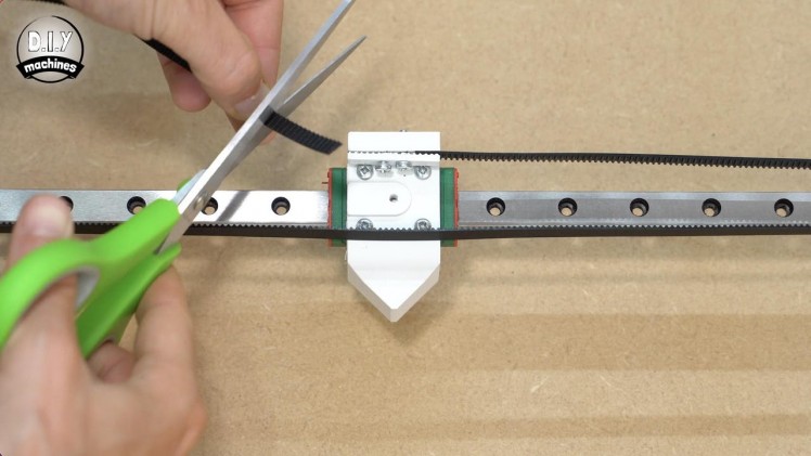
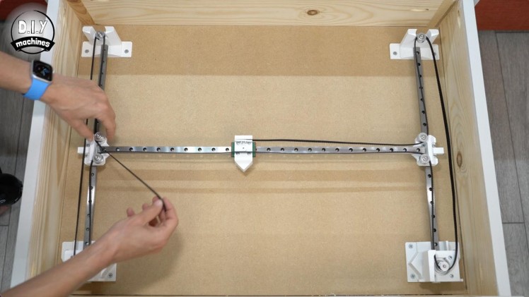
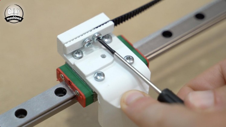
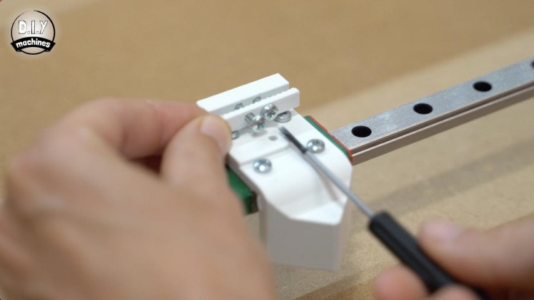
For this step you will need:
3D printed part:
- BeltGripper.stl
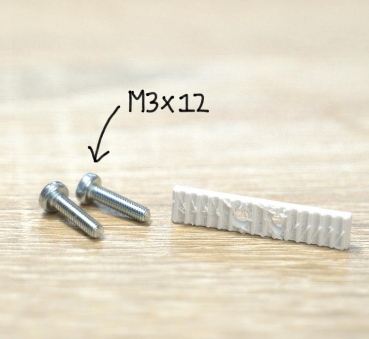
- M3x12 bolts (x2)
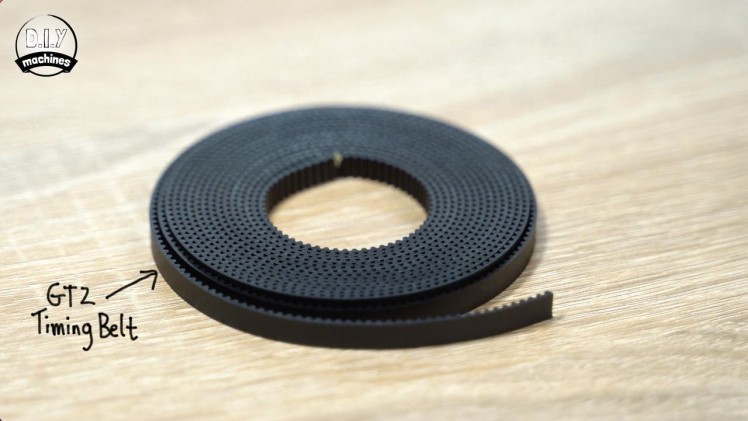
- Length of 6mm wide GT2 timing belt (x1)
- Screwdriver
- Scissors
The timing belt gripper, should be printed with a more detailed layer height and with 100% infill for additional strength.
Fit it to the magnet mount using two M3x12 bolts but do not fully tighten them just yet. The teeth of the 3D printed part should be facing towards the 3D printed magnet mount.
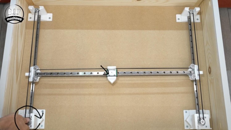
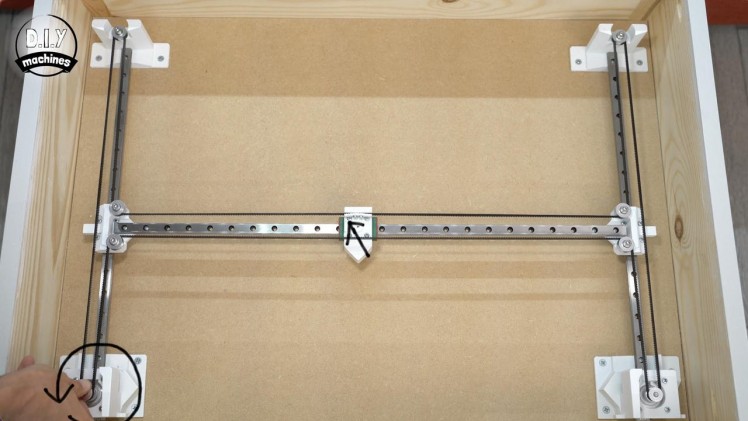
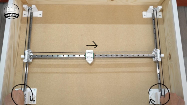
Take one end of your timing belt and clamp it in place using the belt gripper, run it around the mechanism as shown in photos whilst ensuring not to allow any twists in the length. One you get back to the magnet mount, trim it a little oversized to make it easier to handle. We can then refine its length and install it into the other side of the gripper.
The tautness is correct when you can turn one, or both of the motors by hand and get a near instant reaction from the carriage. You need to find the balance between not being so loose as to exhibit backlash, but not so tight that it is difficult turn and it puts unnecessary pressure on the idler wheels.
Step 17: Preparing Baseboard for GRBL Electronics
1 / 5
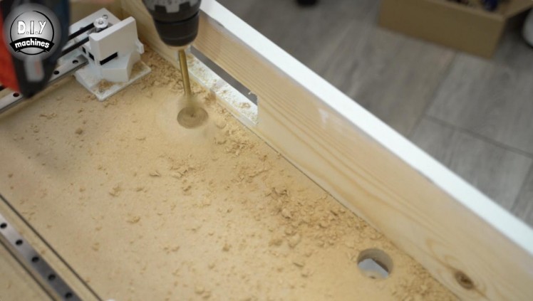
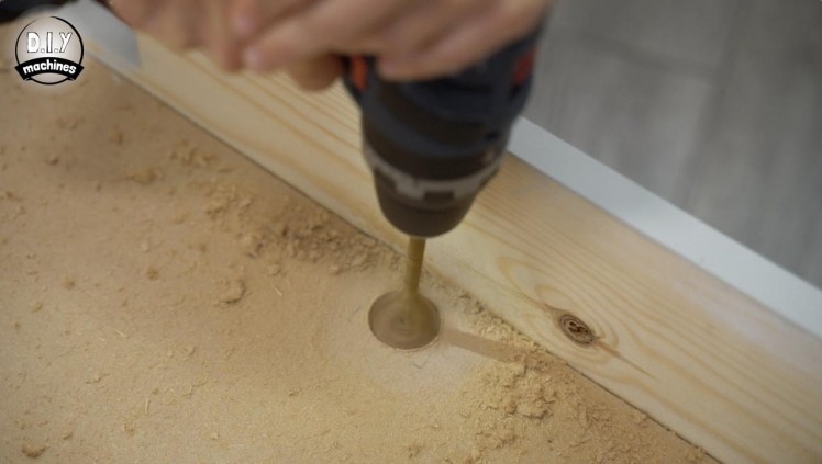
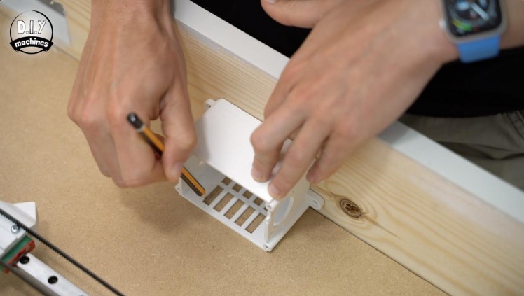
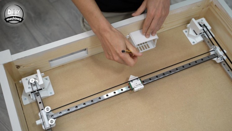
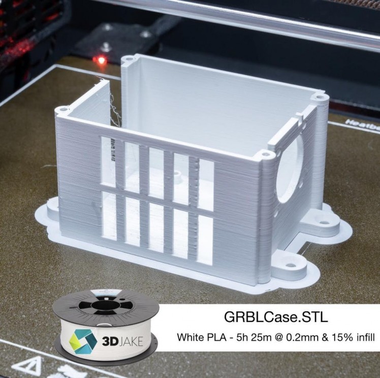
For this step you will need:
3D print:
- GRBLCase.stl (x1)
- Drill
- Drill bits
To house our Arduino Uno we need to print ourselves a case. The case has a hole in the side for a small 5v fan which we will add shortly, and the air flow from the fan is directed out through this side in the side. For this to work we need to make an additional cut out in our 18mm base board panel.
Position the case in the table with the open side against the floor, in roughly the same position as I have in the first photo. Mark where the cut out needs to be made beneath the grill, then remove the case and make the opening in the floor.
Whilst we have our tools out we can also make an additional hole nearer to the control panel with which we can feed our wiring through later.
Step 18: Fitting Arduino Uno
1 / 3
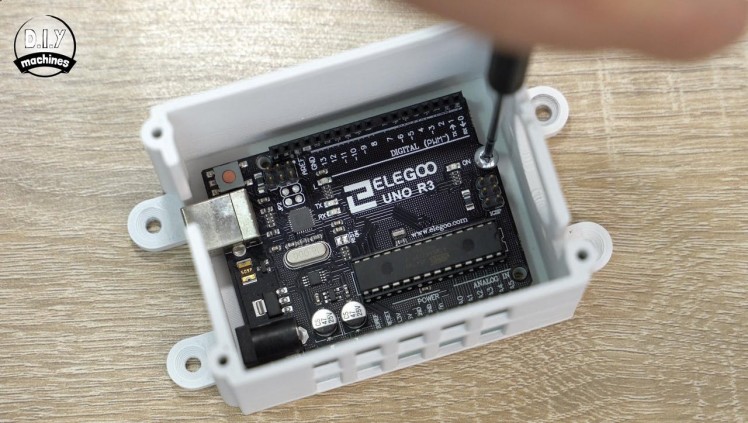
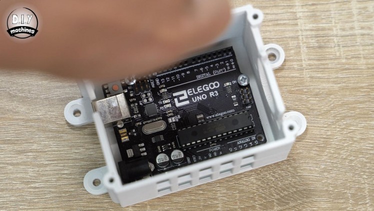
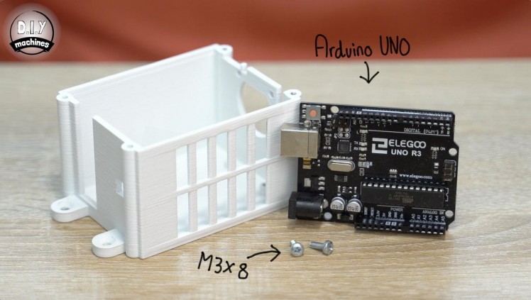
For this step you will need:
- M3x8mm bolts (x at least 2)
- Screwdriver
The Arduino Uno is fitted into the bottom of the case using at least two M3x8mm bolts.
Step 19: Assembling Stepper Drivers
1 / 6
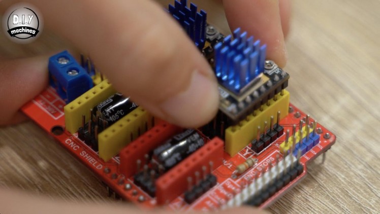
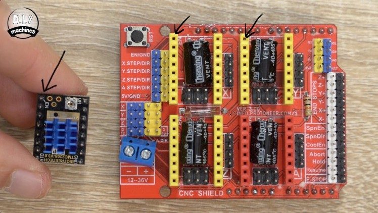
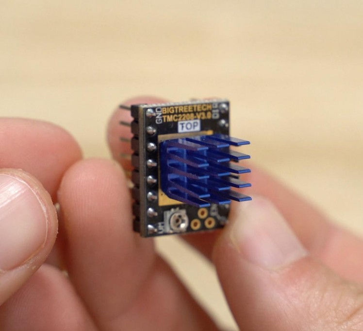
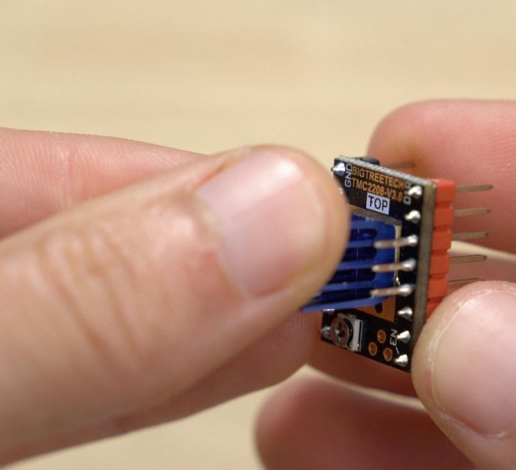
For this step you will need:
- Stepper drivers - TMC2208 (x2)
- Arduino Uno CNC Shield (x1)
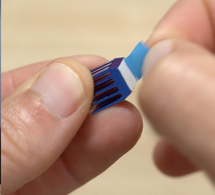
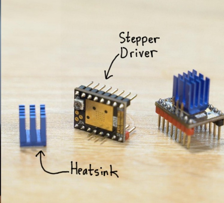
Our two stepper motor drivers should have come with some heatsinks - if these are not already installed then you will need to peel of the self adhesive backing and affix the heat sink on top of the board ensuring that the edges of the heat sink do not come into contact with any other components on the board.
These drivers can then be installed onto the CNC shield. Look for the pin marked as enable on the driver and match this up with the pin marked as enable on the shield. The two stepper motor drivers should be fitted onto the top two axis labelled as X and Y.
Step 20: Calibrating Stepper Drivers
1 / 7

For this step you will need:
- 12v power supply
- Female barrel connector (x1)
- Some wire
- Multimeter
- Soldering iron
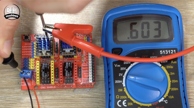
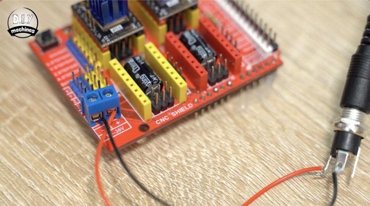
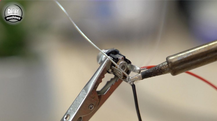
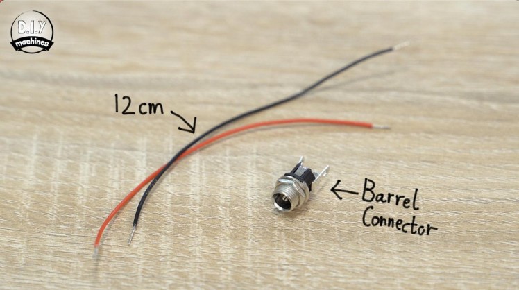
We need to set the current of our stepper drivers which is easily done with a multimeter and a small screwdriver. We will also need to use our power supply so let’s solder some wires onto the barrel connector.
Prepare two 12cm long wires and solder them to the bottom and right most pins of the barrel when looking at it from behind. I’m using red and black wires to make it easier to follow the polarity throughout the project.
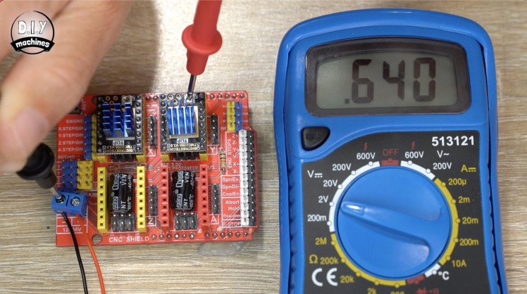
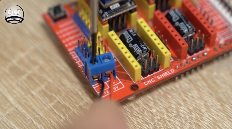
We can then attach the power supply to our CNC shield being mindful of respecting live equipment. Set your multimeter to measure volts, 2v should be plenty and then place the positive probe in the centre of the adjustable potentiometer (pot) and the negative probe on the negative terminal of the CNC shield. Take note of the reading - for our project a value of 0.6v is ample. To adjust it, use a small screwdriver to turn the pot slightly before taking another reading.
You can also clip a positive crocodile probe to the screwdriver allowing you to take measurements continually as you adjust the pot. Adjust the pot until you get as close to 0.6v as you can. Repeat this again for the second stepper driver.
We can then unplug and disconnect the power supply. We will use the barrel connector and its 12cm wires later.
Step 21: Continue Fitting GRBL Case
1 / 12
For this step you will need:
- Some wire
- 30mm 5V Fan and its screws (x1)
- Stepper motor wires (x2)
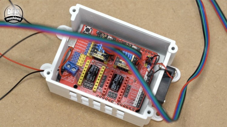
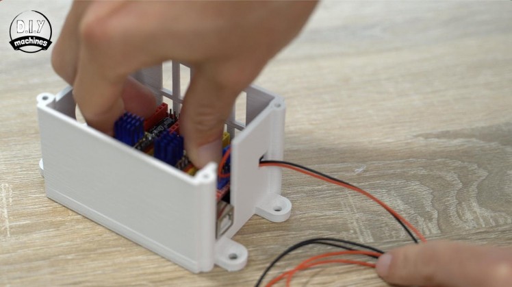
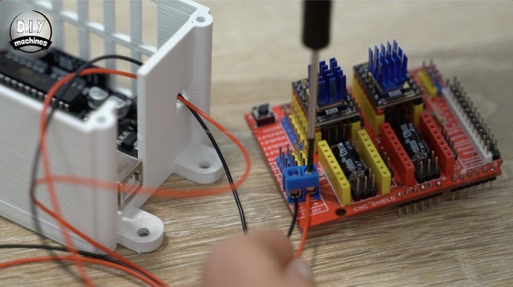
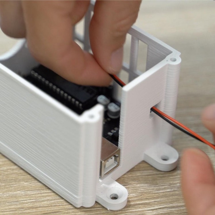
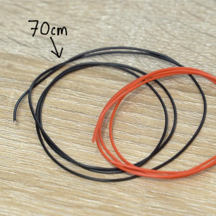
Thread a pair of new 70cm long wires through this opening in our case Connect these to the motor shields power terminals and then install the CNC shield on top of the Arduino Uno.
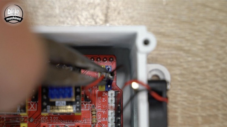
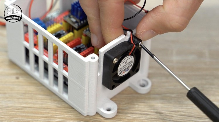
The 5V fan is attached to the case using the included screws, with the power leads being fitted to the pins marked as 5v and GND towards the top right of the CNC shield.
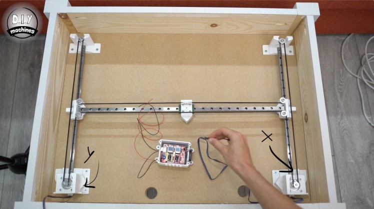
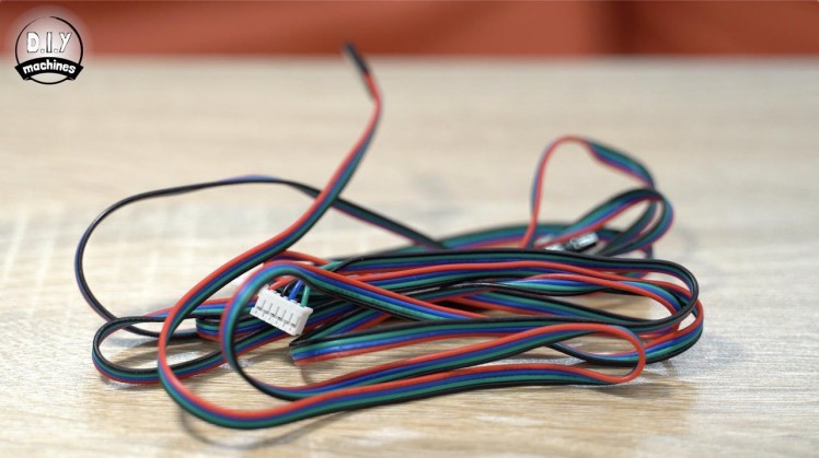
Connect the leads for the two stepper motors to the motors (they are keyed and will only fit one way) and then, when looking at the table with the motors closest to you, connect the right hand motor to X axis driver board with its black wire towards the top of the shield, the left hand motor connects to Y axis also with its black lead towards the top.
Step 22: Homing Switches - Preparing
1 / 6
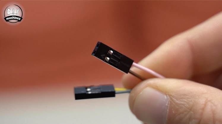
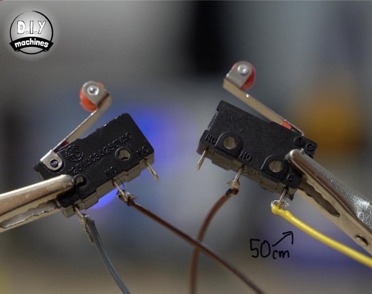
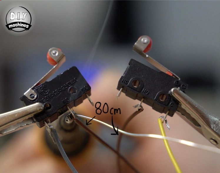
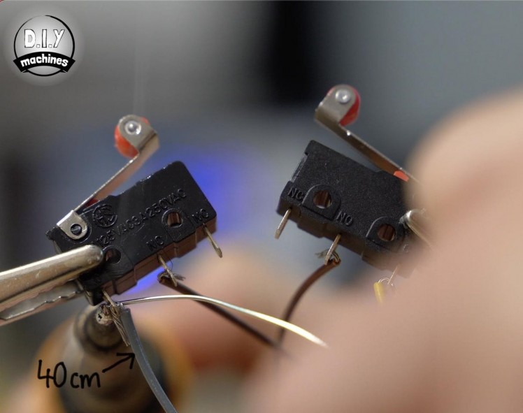
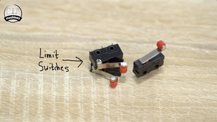
For this step you will need:
- Limit switches (x3)
- Soldering iron
- Some wire
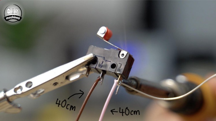
To enable the CoreXY style machine to home we need to add three limit switches.
To the first limit switch solder a pair of 40cm wires to the normally open pins - for me this the centre pin and the pin where the arm connects. This is the brown and pink wires in the second photo above.
The next two switches are connected in series with a 40cm wire (grey in the photos) going to the first switches central normally open pin, a 80cm (brown in the photos) then connect this first switches common pin to the second switches central normally open pin and finally a 50cm (yellow in the photos) wire is connected to its common pin.
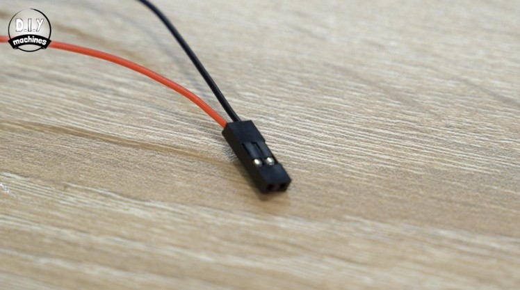
To connect these wires to the pins on the CNC shield I recommend adding some Dupont style connectors. It’s very easy to do. I’ve made a separate video showing just how easy. Alternatively you could cut the end from a female jumper wire and solder that to the end of the wire or even solder directly to the legs. But I highly recommend the connectors.
Add the connectors to all four unconnected wire ends.
Step 23: Homing Switches - Installing
1 / 7
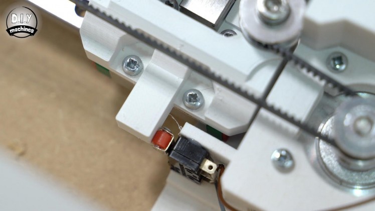
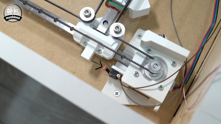
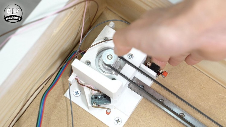
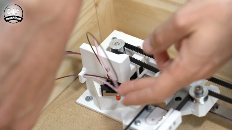
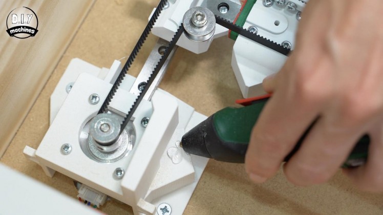
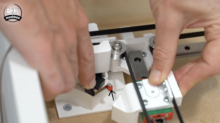
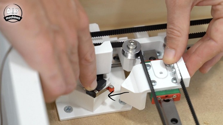
We next need to fit the limit switches used for the homing routine to our machine.
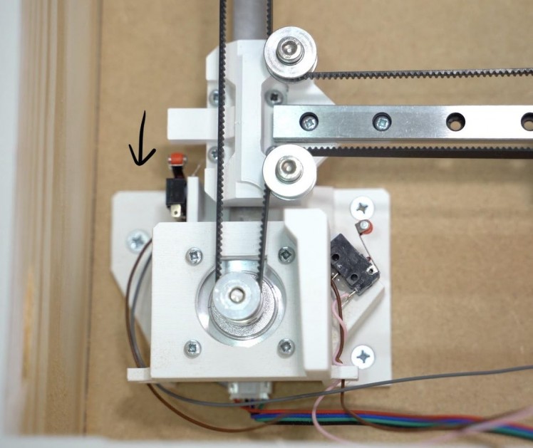
The single limit switch is affixed to the left side 3D printed motor housing at a 45 degree angle so as to be able to be triggered when the magnet mount approaches it from either the side or from above.
Fit it in place with some hot melt glue, this allows us the opportunity to tweak its position later if we need to. The wires for this can then be passed through the wire loop to help keep them from interfering with the mechanics when in motion.
The first of the two connected limit switches is fitted vertically with the front of the switches body flush with the front of the 3D print (See the 5th photo). This should be triggered when the X carriage moves to the bottom end of the machine. The second switch is then fitted to the other motor mount so that both sides are effectively mirrors of each other.
Step 24: Homing Switches - Connecting
1 / 3
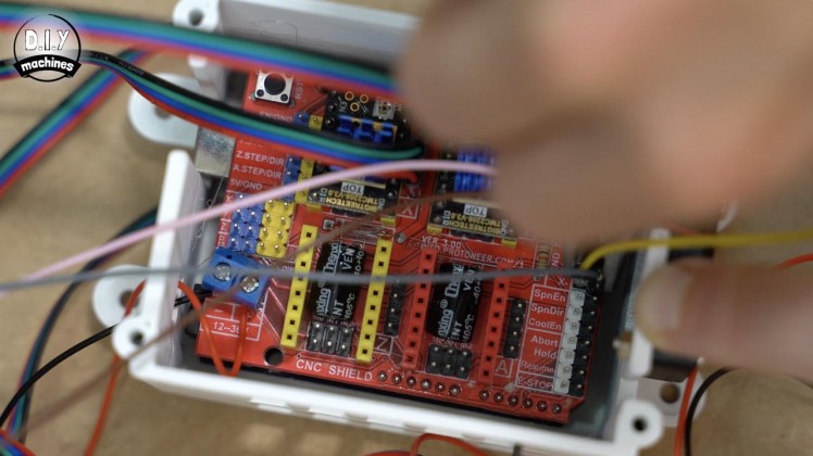
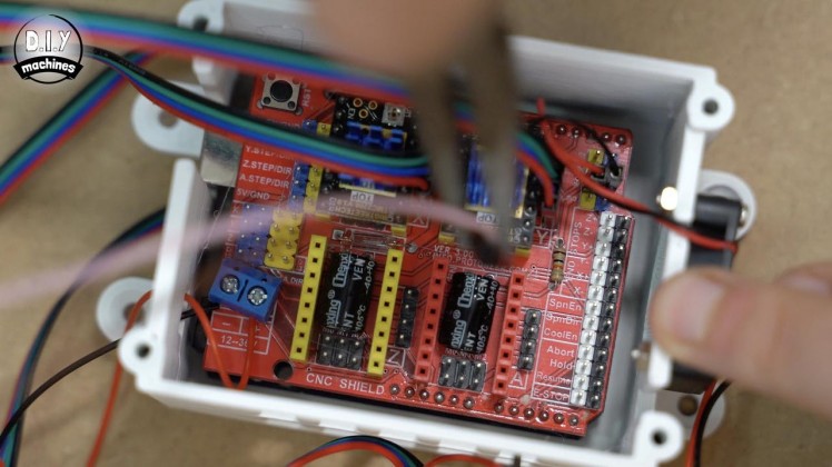
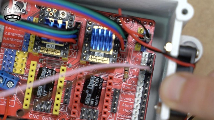
To connect the limit switches to the CNC shield take the pair of wires coming from the single limit switch (the one we installed at 45 degrees) and connect them to the pair of pins marked as 'Y-' in the 'Endstops' section of the CNC shield.
The wires coming from the remaining pair of limit switches should be connected to 'X-'. Simple as that. :)
Step 25: Uploading GRBL
1 / 8
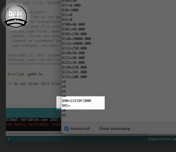


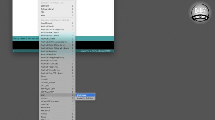
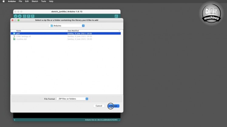
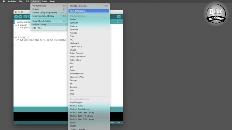
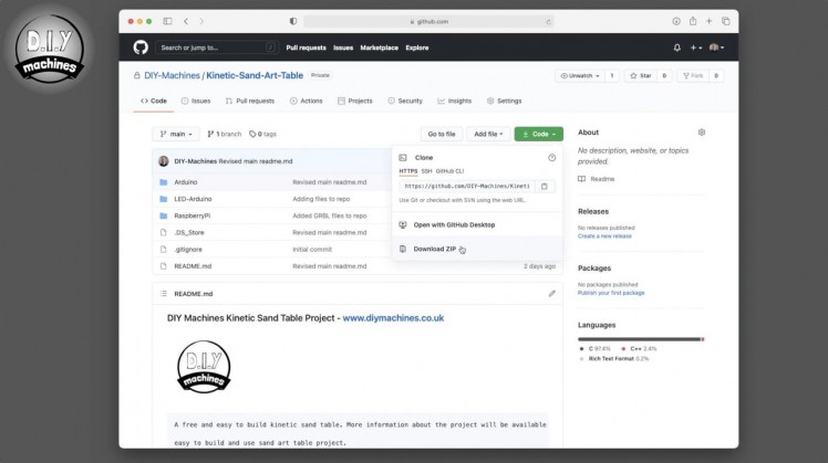
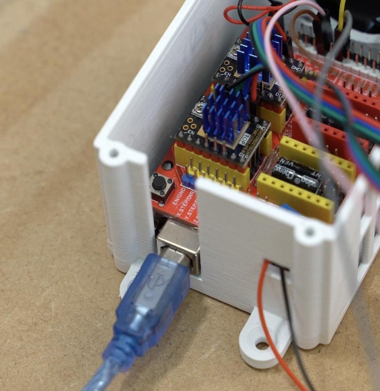
We can now upload our pre-customised GRBL software to the Arduino Uno so that we can test our mechanism to ensure that everything we have done so far works as intended. To do this, simply connect your PC to the Arduino UNO using a USB cable and download the code for the project - the code can be downloaded from Github: https://github.com/DIY-Machines/Kinetic-Sand-Art-...
The code is hosted on Github where you can select ‘Code’ and then ‘Download ZIP’. Unzip this folder and save it somewhere on your computer. Now open the Arduino IDE and then in the Sketch drop down select ‘Include Library’ and then ‘Add a zip library’. Find the file you downloaded from Github which should contain a folder called ‘Arduino’ open this and select the GRBL folder and add it.
We can then navigate to 'File' --> 'Examples' --> 'GRBL', and select 'GrblUpload'. Select the board type - Arduino Uno and correct serial port for your board then press upload.
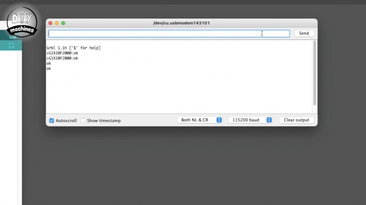
Once the upload is complete you can open the Serial Monitor and set the baud rate to 115200, sending two dollar signs - $$ - should return GRBLs current settings.
To set a command which we want to run at power up, enter the following into the serial monitor:
$N0=G1X10F2000.
To check the start up code we have added send $N which should echo back the parameter we just sent along with a blank value for N1
Step 26: Making Our First Moves
1 / 6

For this step you will need:
- Barrel connector with 12cm wire we created earlier (x1)
- Three way wago style connectors (x2)
When we power on our machine it will not yet know the location of the raft, so we can trigger the homing sequence manually.
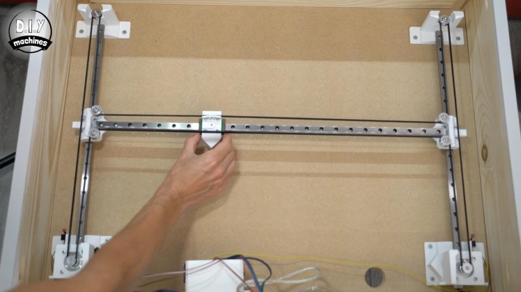
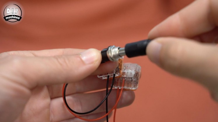
Gently move the raft towards the centre of the machine area and then connect the 12v power to the CNC shield. This can be done temporarily by using two of the wire connectors we have for use later to connect the wires from the barrel connector to the long wires coming from the CNC shield.
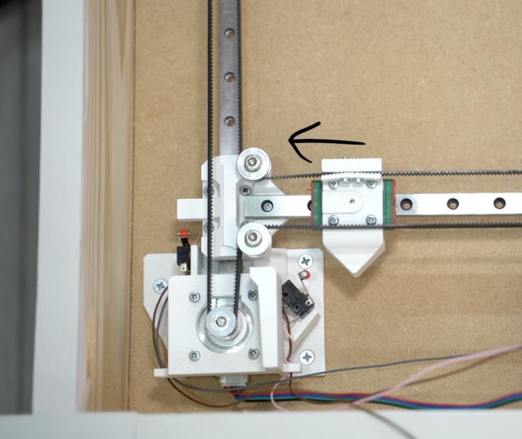
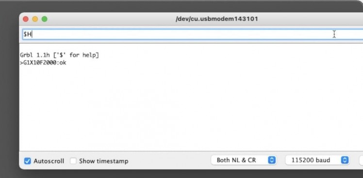
The command to trigger the homing is $H. We expect to see machine move the magnet raft downwards until it has made contact with both vertical limit switches, it will then move back and then make a second contact with both switches. After this the magnet raft will move to the left towards the horizontal switch until it makes contact and then confirms this with a second activation. If yours does anything else then should immediately switch off the 12v power and check your work up to this point.
If your’s successfully homes and reports 'OK' we can proceed to send it some further commands
Step 27: Sending Some GCODE
1 / 3
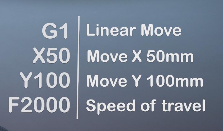
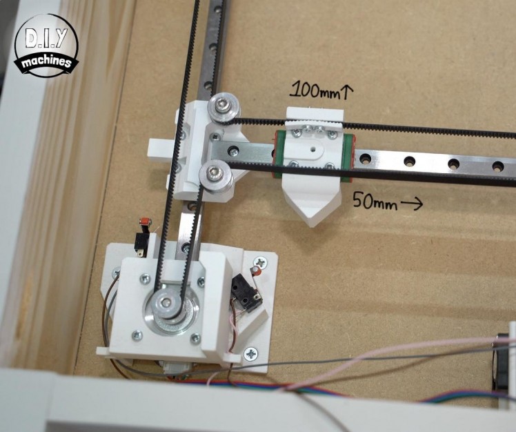
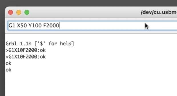
Let’s move the magnet raft using GRBL which is a great way to test everything is working OK so far. To do this we can send a command such as:
G1 X50 Y100 F2000
Your machine should move sideways about 50mm and upwards about 100mm.
If you're interested - the value for G sets the type of movement - 1 means a linear move in a straight line. The values for X and Y are where in the co-ordinate space we want the machine to move to in MM and the value of F is the feed rate or speed of travel.
There is no need to worry about it if these GCODE commands and homing sequences all seem a lot to remember, as our Raspberry Pi that we will add later will take over all the responsibility of talking to GRBL on the Arduino UNO. :)
We can disconnect the power supply again.
Step 28: Sand Sub-surface - 3mm Board
1 / 4
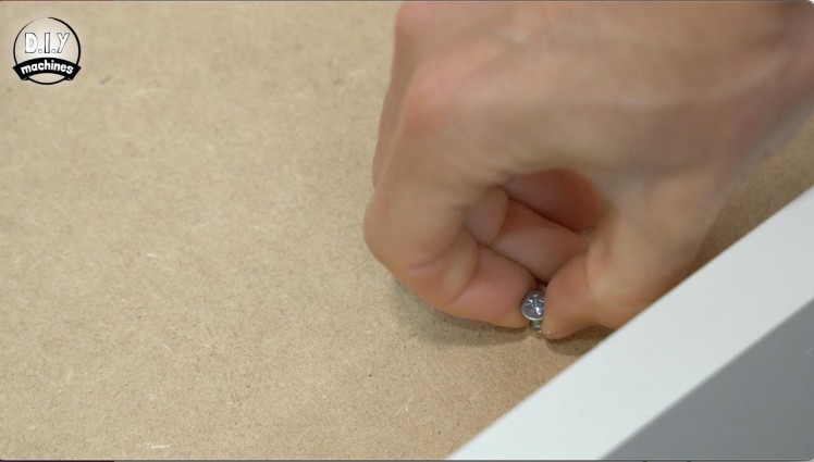
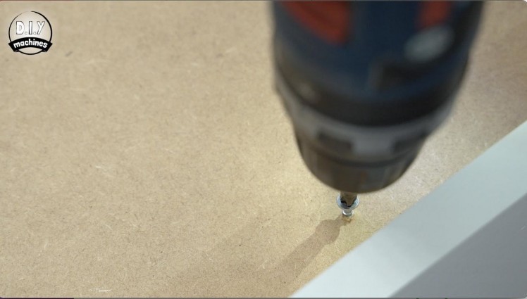
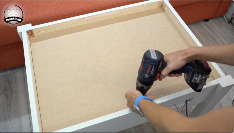
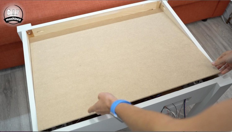
For this section of our build we need to cut our 3mm panel down to size, I suggest taking measurements from youre own table and then trimming your board down so that it is about 3mm shorter in both directions.
This will make it easier to insert and remove the panel. Later we will add some 3D printed parts to make it simpler to move the board and hold the LEDs in place, but for now we can use a partially inserted wood screw added near the edge to help pick up the board when we need to move it.
Step 29: Adding the Magnets
1 / 4
For this step you will need:
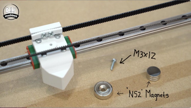
- At least one countersunk magnet (x1)
- M3x12 bolt (x1)
- Additional magnets
- Screwdriver
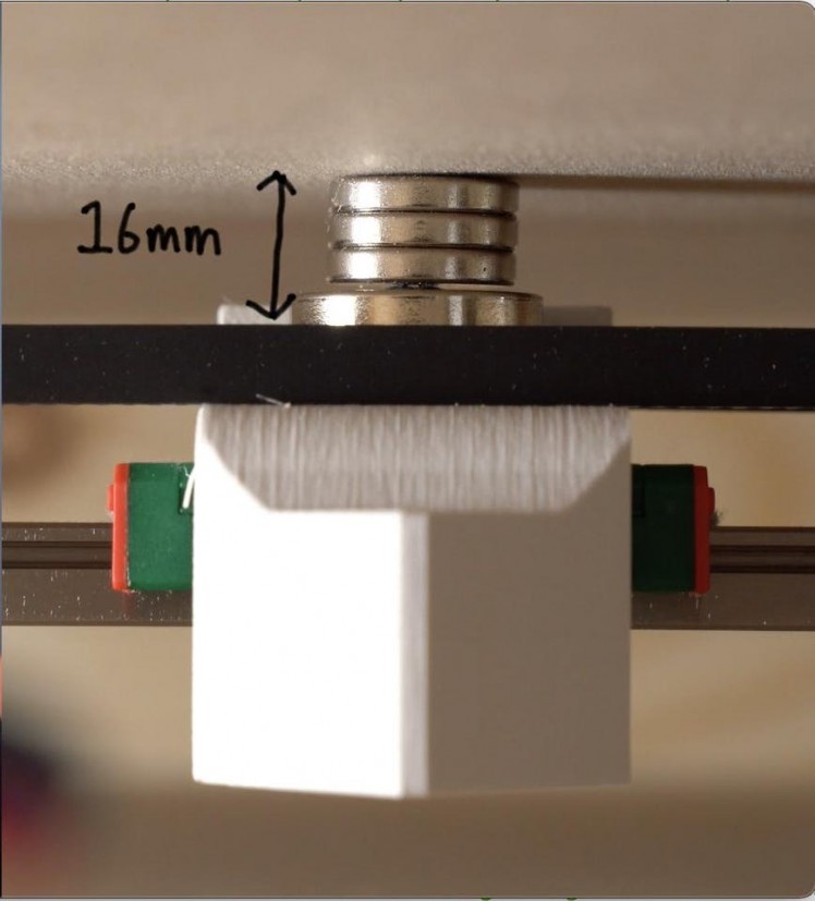
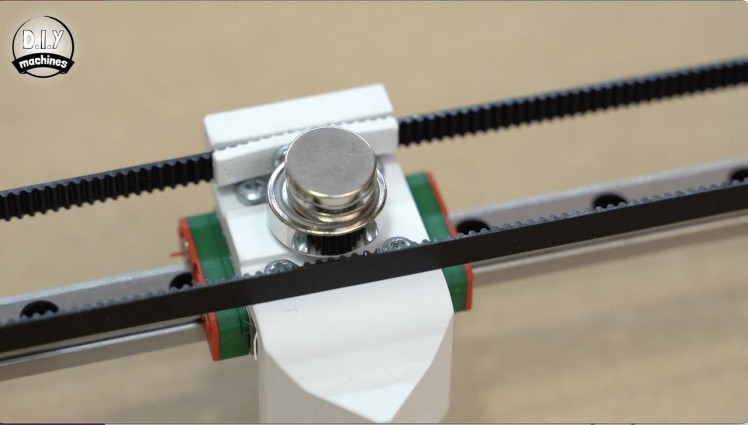
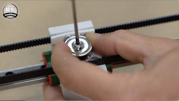
Once the board fits nicely, remove it and then attach your countersunk magnet using a M3x12 bolt to the 3D printed magnet mount. You can then add your additional magnets on top of this.
You have roughly 16mm of space to fit your magnets between the top of the raft and the bottom of the baseboard. The magnets should be as close to the board as possible without touching it so as to keep noise to a minimum, while trying to maximise the magnetic pull on the steel ball.
Step 30: Tidying the Wires
1 / 13
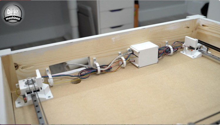
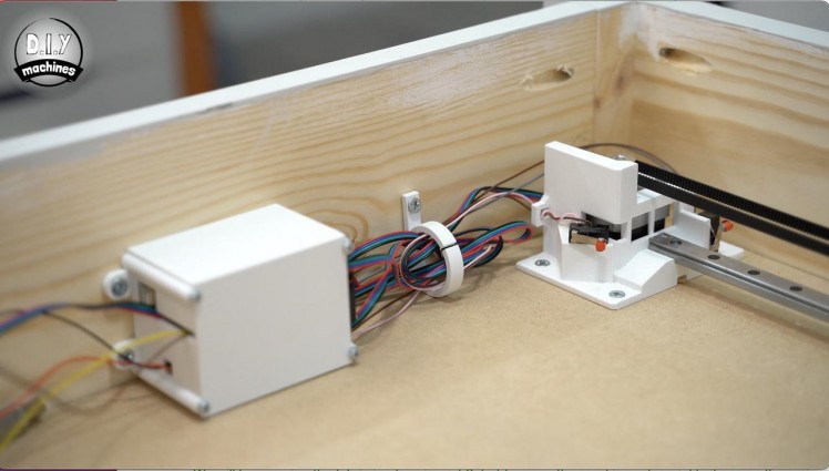
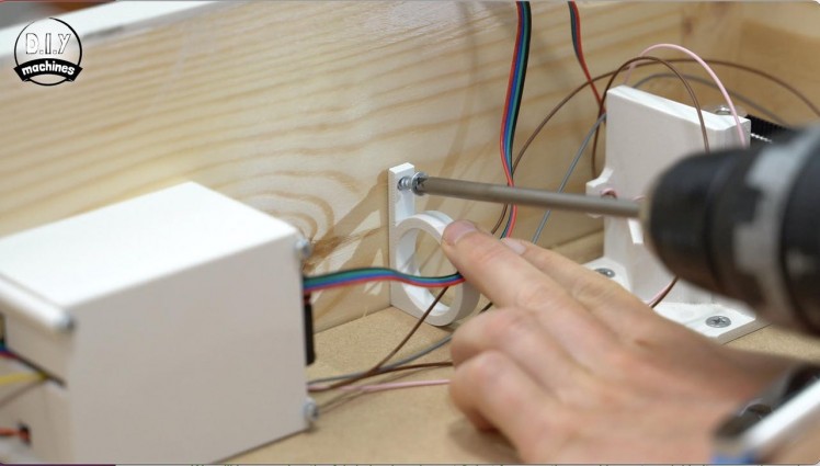
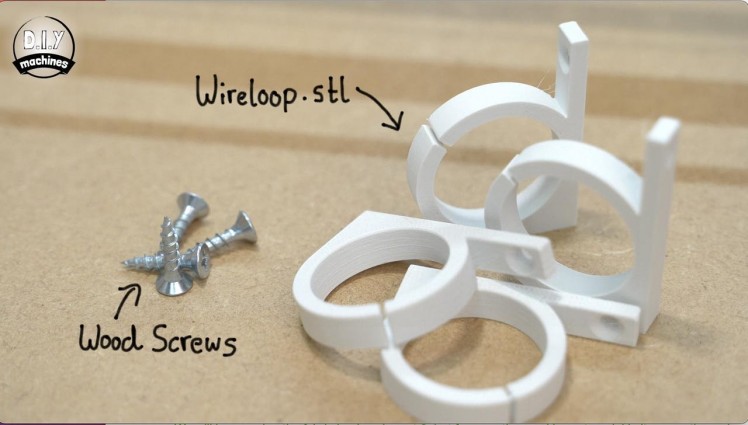
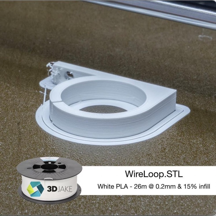
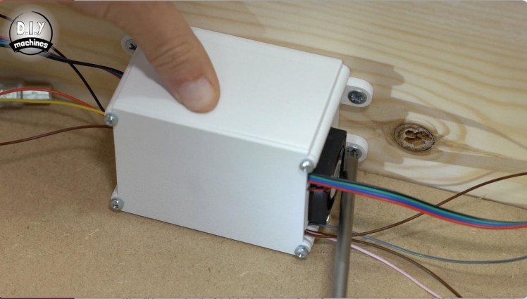
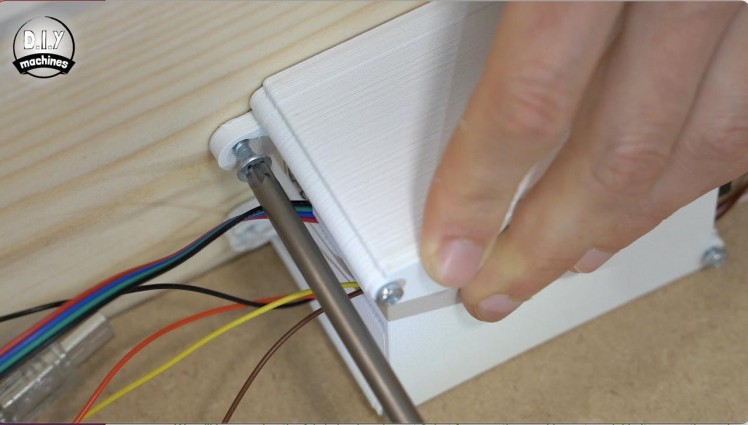
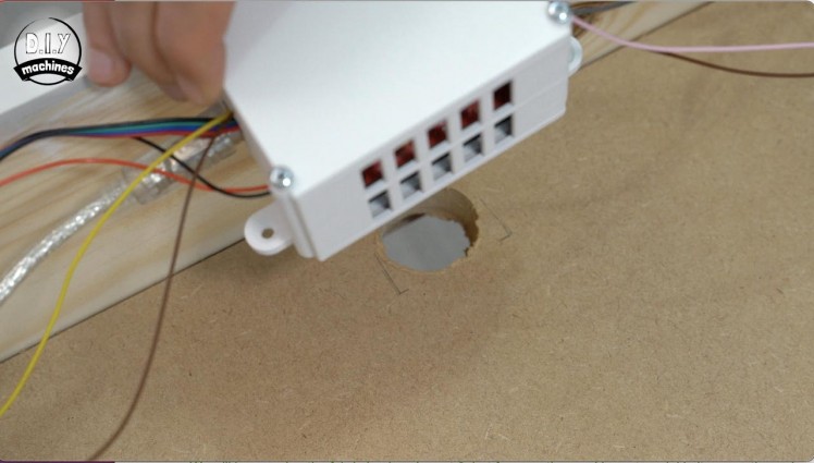
For this step you will need:
3D printed parts:
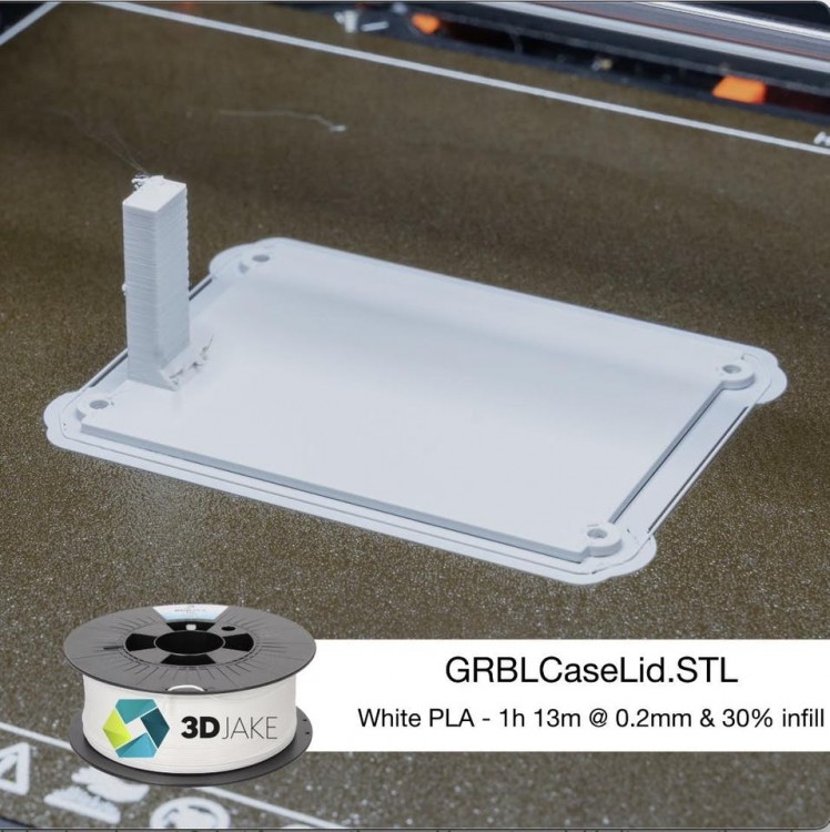
- GRBLCaseLid.stl (x1)
- WiringLoop.stl (x4 or more)
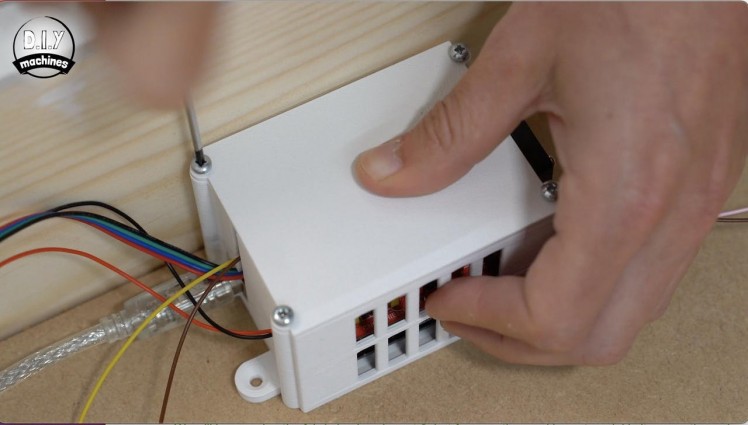
Before we add some sand and fabric we need to ensure that the wires don’t get caught in the mechanism. We can do this by adding a lid to the GRBL electronics and some wire tidies to contain the wiring.
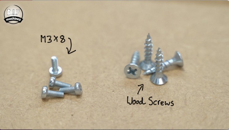
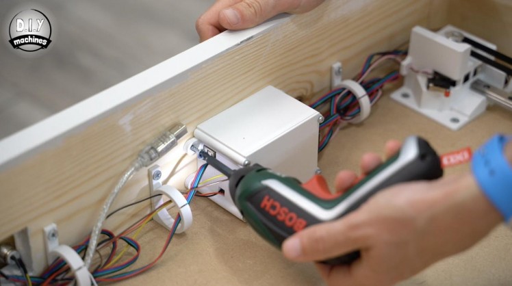
The lid is fitted into place using four M3x8 bolts. Be careful not to trap any wires whilst ensuring they exit out from an appropriate side.
We can then secure the electronics housing with some wood screws. It should be positioned so that our housing is against the cut out we added earlier in the baseboard to allow the fan to pull fresh air through our machine.
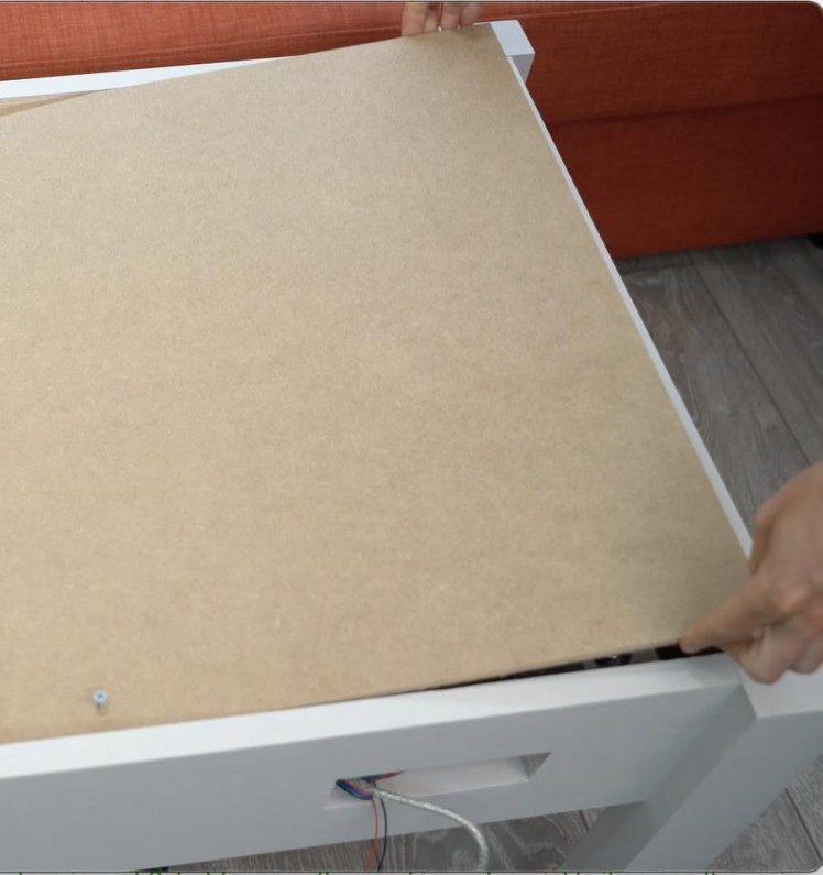
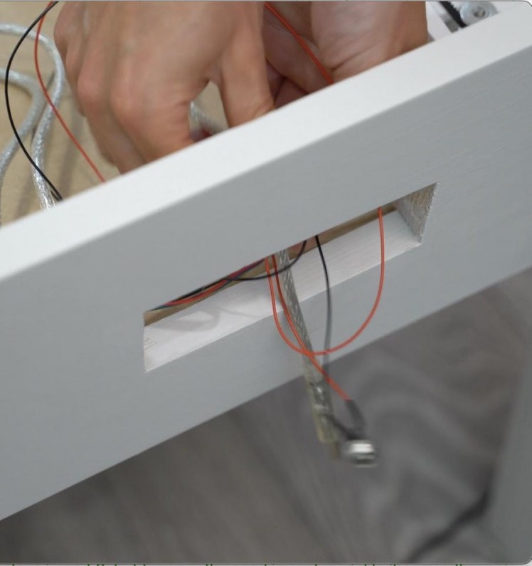
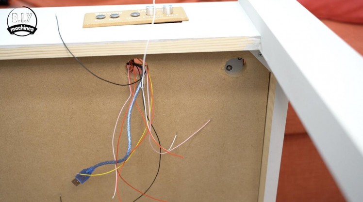
Several cable tidies can then be printed and secured along the same wall using wood screws. The wires are then tidied away into these. For now, feed the USB and power cables through the cut-out we made for the control panel which we will be adding in a later step for this project. After the wiring is secured out of the way of the mechanism we can replace the 3mm baseboard.
Step 31: Cutting the Fabric
1 / 4
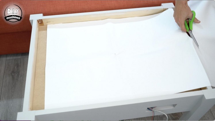
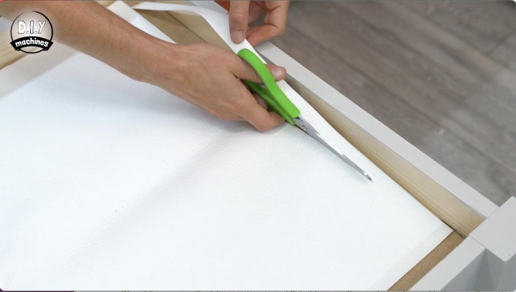
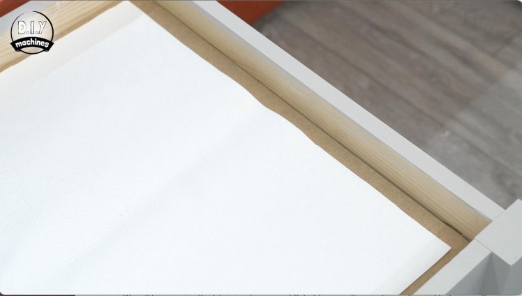
For this step you will need:
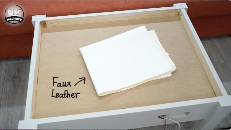
- Faux leather fabric (enough to cover the baseboard)
- Scissors
Lay the fabric out across the top of the table and then cut it so that it is roughly 1cm shorter on each side than the 3mm baseboard
We will be using some 3D prints later to secure the fabric in place but for now, the sand is next.
Step 32: Adding the Sand
1 / 7
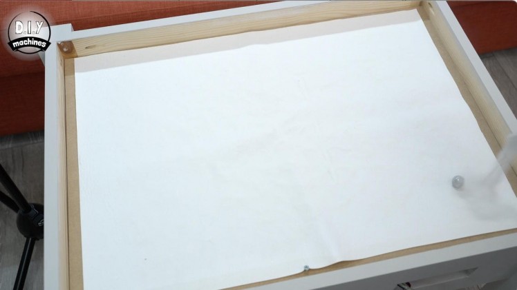
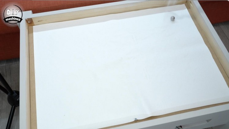
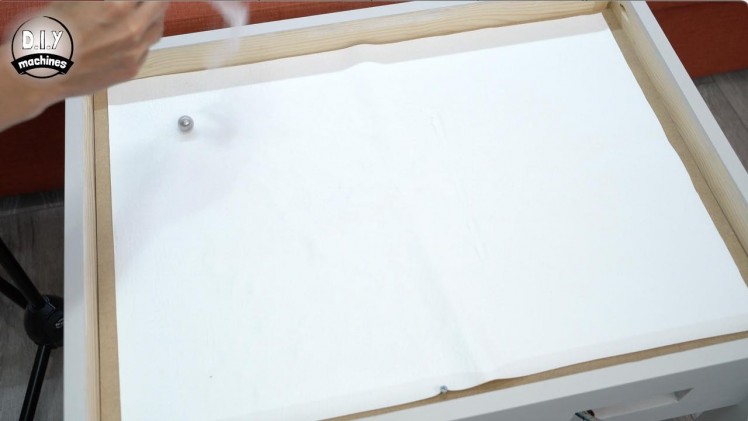
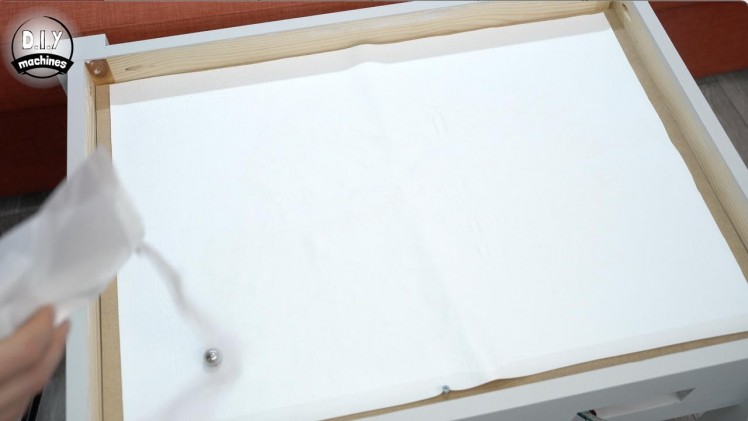
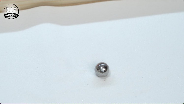
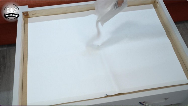
For this step you will need:
- Craft sand (about 600g worked for me)
- Steel ball - 20mm (x1)
Sprinkle some of the sand across the main drawing area in the centre so it just covers the fabric. When we have the ball moving shortly we can add more or remove it as required.
The steel ball is then placed into the influence of the magnets beneath the board.
Connect the 12v power supply, connect your computer to the Arduino’s USB connection and then open the serial monitor from within the Arduino IDE. We first need to home the mechanism by sending the $H command. Once we have received OK from GRBL we can issue some commands to see the extent of the drawing area so that we may add some more sand as required to the drawing surface.
Add some to the area up-to where the ball is now in the homed position in the bottom left. Then send the command ‘G1 Y325 F2000’ this will send the ball to the top left corner, again add some additional sand if required. Sending ‘G1 X520 F2000’ will move the ball to the top right, and then ‘G1 Y0 F2000’ will move it to the bottom right.
It may be difficult to see at the moment, but try to spot any areas where the sand is missing within an imaginary bounding box formed from the four corners the ball just visited. Later any missing areas will become more apparent and can be topped up with more sand.
Step 33: Framing the LEDs
1 / 5
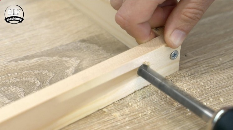
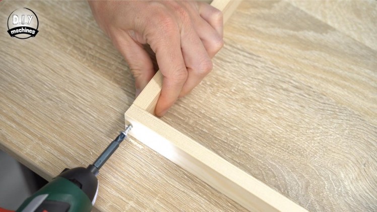
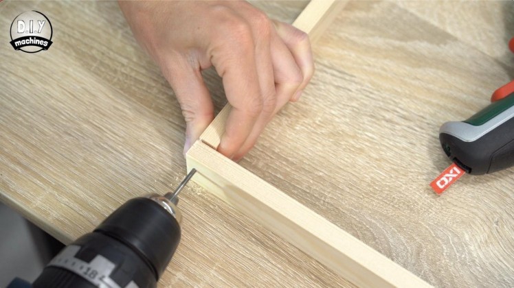
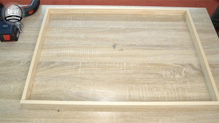
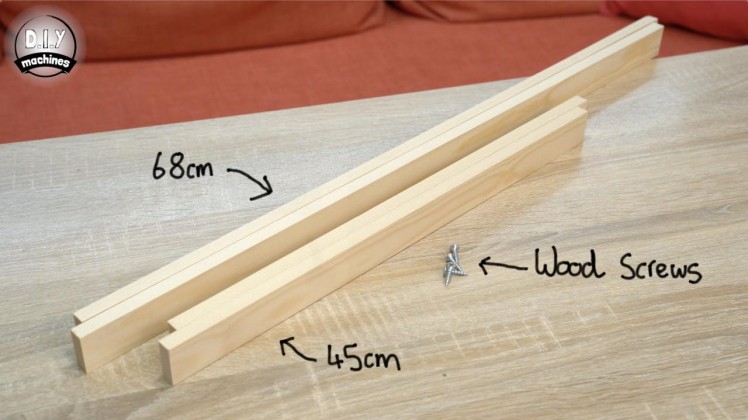
For this step you will need:
- Wooden strips
- Drill an drill bits
- Screw driver
- Short wood screws (x4)
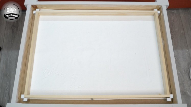
We need to assemble a simple frame to hold our LEDs in position. For this, you will need to cut two lengths of 68cm long wooden strips, and two lengths 45cm long. They need to be narrow enough so as to not to sit proud of the side of the table once installed on top of the faux leather.
They can then be assembled with the two shorter lengths inside of the two longer lengths and held together with either screws or glue (or both). If you are using a screw I encourage you to first drill a pilot hole so as to reduce the chances of our wood splitting as we are drilling so near the ends.
After this, make a small hole just larger than the width of the LEDs about 2cm inwards from the end of one of the long lengths. We will pass the wiring for the LEDs through this later.
Step 34: Securing the LED Frame
1 / 6
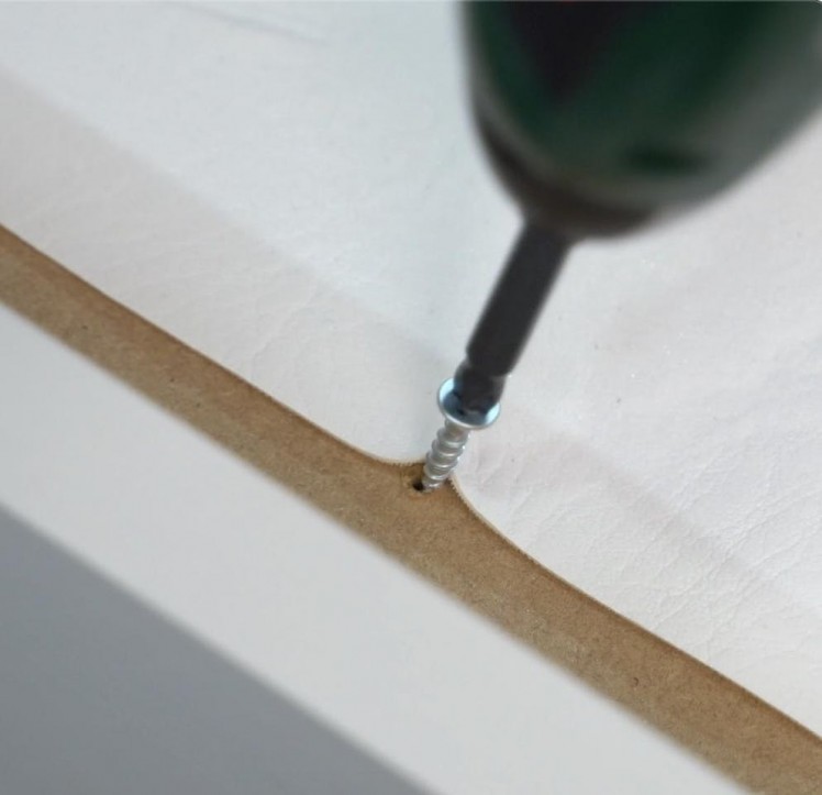
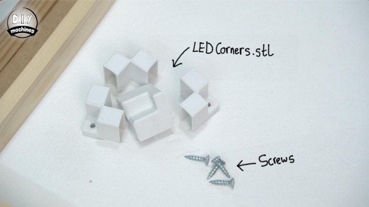
For this step you will need:
3D printed parts:
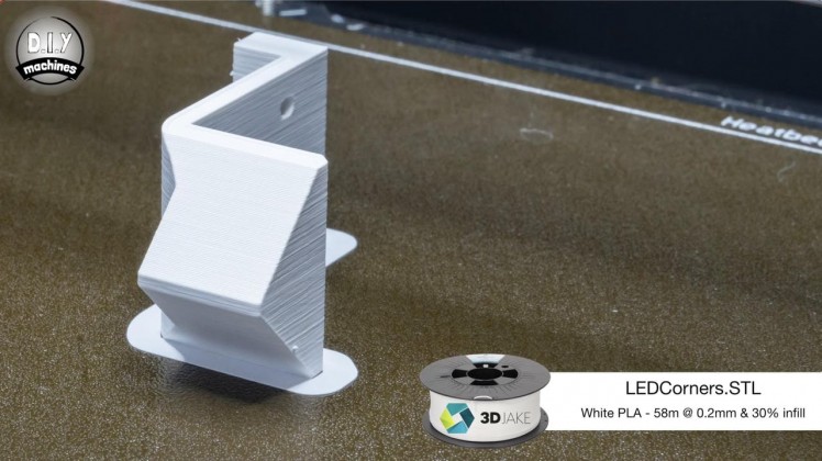
- LEDCorners.stl (x4)
- Short wood screws (x8)
- Screwdriver
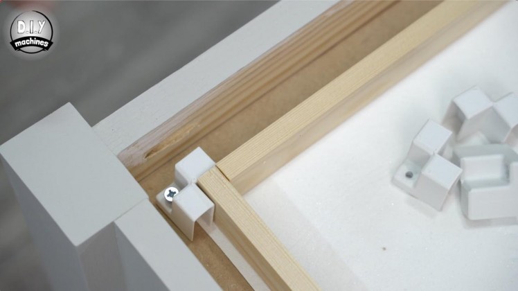
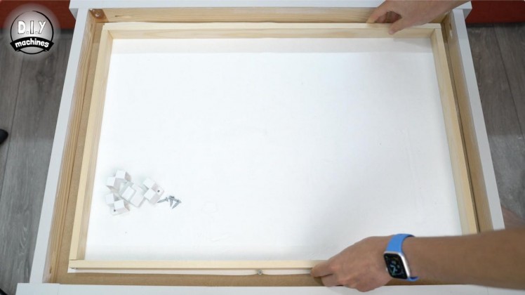
We can then use four of our 3D printable LED Corners to hold it in place in the centre of our table. When fitting the corner pieces ensure that the fabric our sand is sat on is pulled taut. Any bumps left in the fabric are likely to cause our ball to detach itself from the magnets influence whilst drawing.
Use some short wood screws to fixe the four corners into place - the don't need to be super snug against the frame.
As our corner pieces also double up as handles to lift the top out, we can now remove the temporary screw we used in the first video.
Step 35: Fitting the LEDs
1 / 8
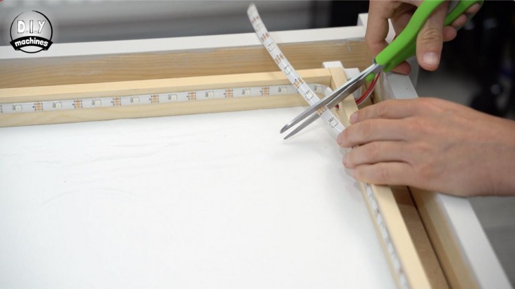
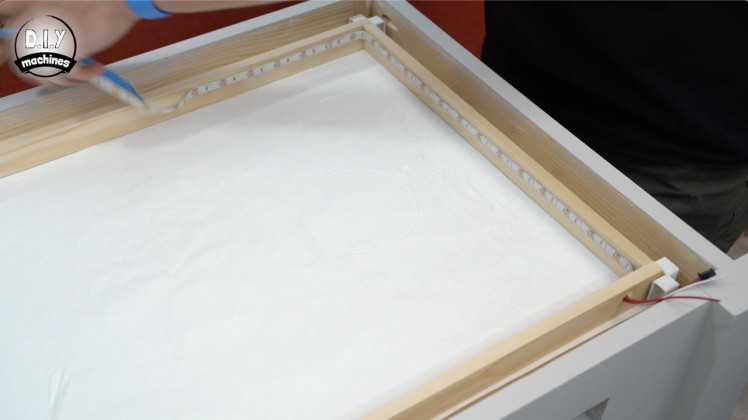
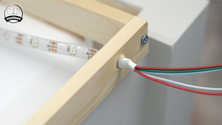
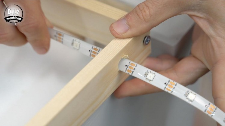
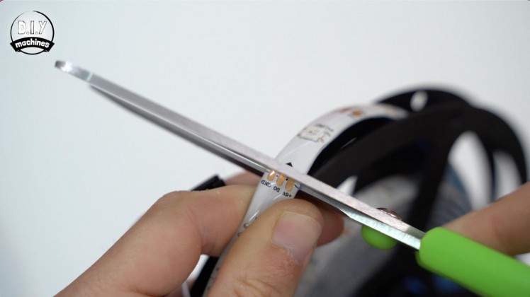
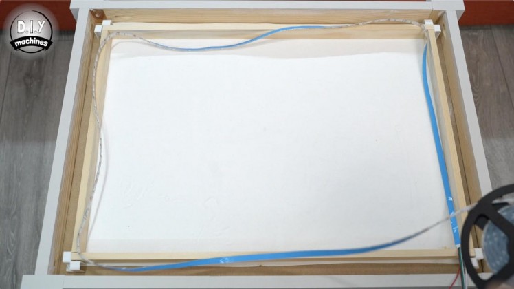
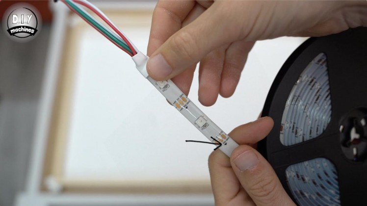
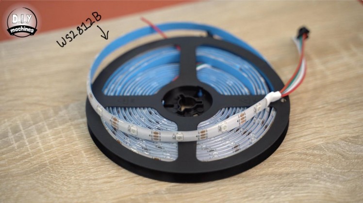
To prepare the LED’s, starting from the end with a connector and the directional arrows pointing away, roughly run a length around the inside of the wooden frame and then cut a little oversized ensuring you cut though the centre off the pads as indicated. We can refine the length shortly.
Thread them through the hole (following the directions of the arrows printed on the LED strip) and then install them by removing the self adhesive backing as you go, pushing them firmly against the wood. Mine adhered fine, but you might need to use glue if you run into difficulty getting them to stick.
When you get all the way around you can trim off any surplus LED's before sticking down the end of the strip.
Step 36: Wiring the LEDs
1 / 8
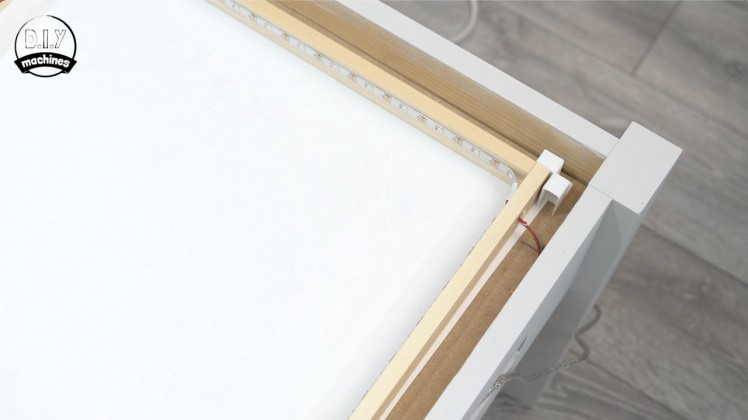
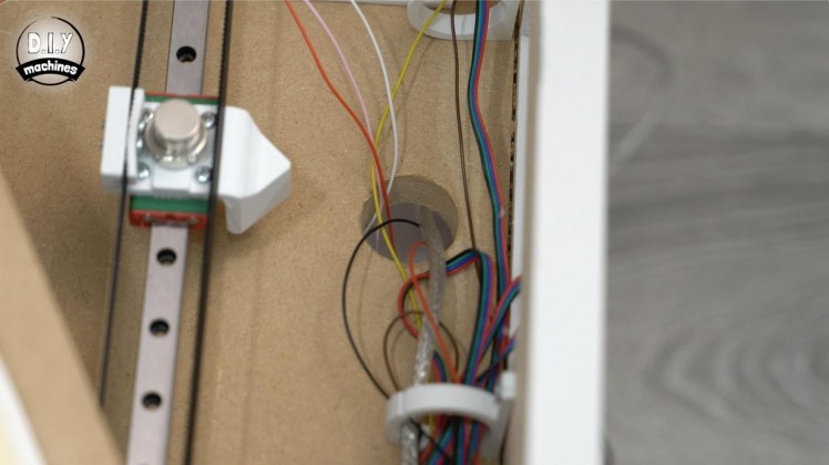
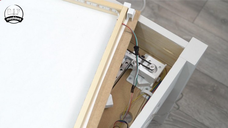
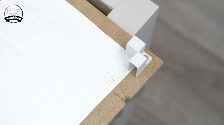
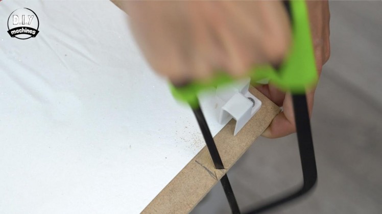
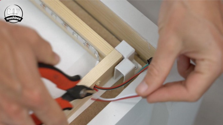
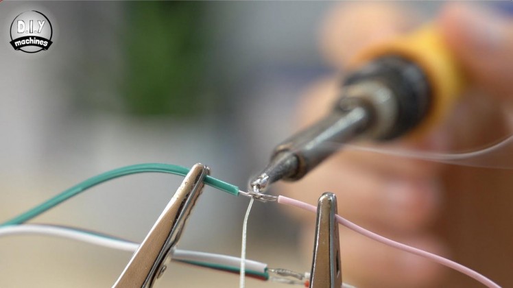
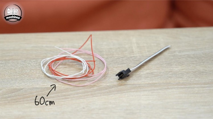
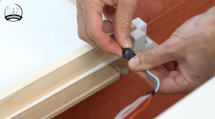
To be able to easily disconnect and remove the LED's frame later if we need access to the internals, we will use the plugs supplied with the LEDs. Prepare three 60cm lengths of wire and solder them to the red, green and white wires coming from the end of your female connector.
We can also trim off the additional red and white wires from the male end of our LEDs. Join the two connectors.
Make a small notch at the edge of the 3mm board so that the LED wires can pass the 3mm board on their way to the underside of the base board. We can then thread the unconnected ends of the LED wires through the hole in the 18mm baseboard which we made adjacent to where the control panel will be fitted later.
Whilst here we can also thread the USB and power leads for the CNC shield though this same hole.
Step 37: Preparing the Control Panel
1 / 4
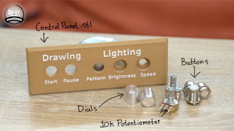
For this step you will need:
3D printed parts:
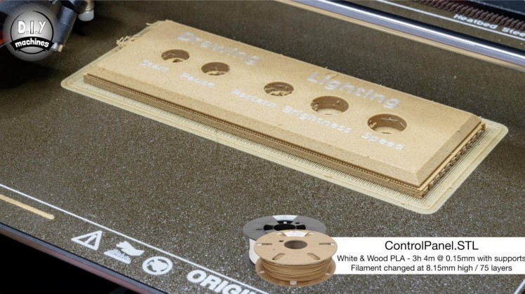
- ControlPanel.stl (x1)
- 10k Potentiometer (x2)
- 12mm Momentary push button (x3)
The control panel is next and requires a 3D printed part, the aptly named Control Panel. :)
This is the only part in this project that requires printing with supports. I also changed the filament for the last few layers so that the text stands out a little more.
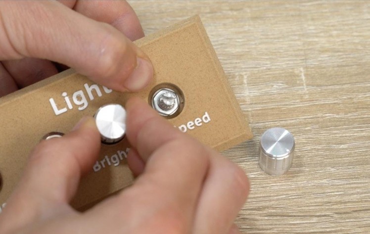
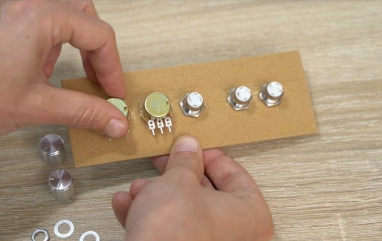
Begin by fitting the buttons and dials into the appropriate recesses. The buttons are inserted from the front side and a nut holds them from behind the control panel, where as the potentiometers are inserted from behind with their nuts securing them at the front.
Step 38: Wiring the Control Panel
1 / 11
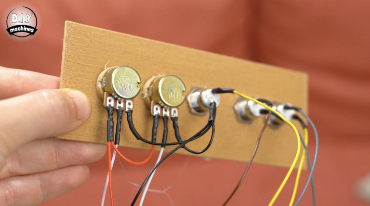
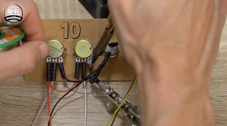
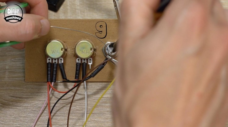
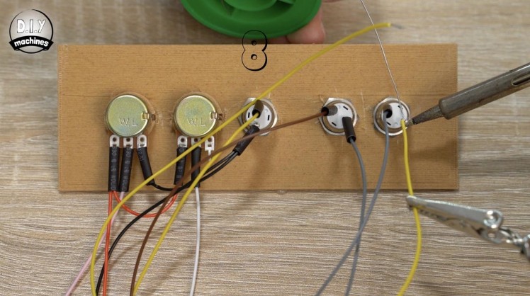
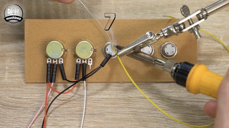
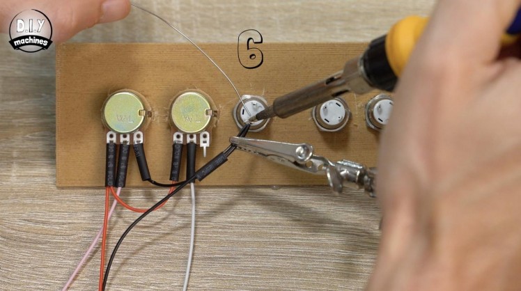
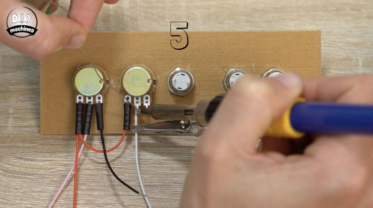

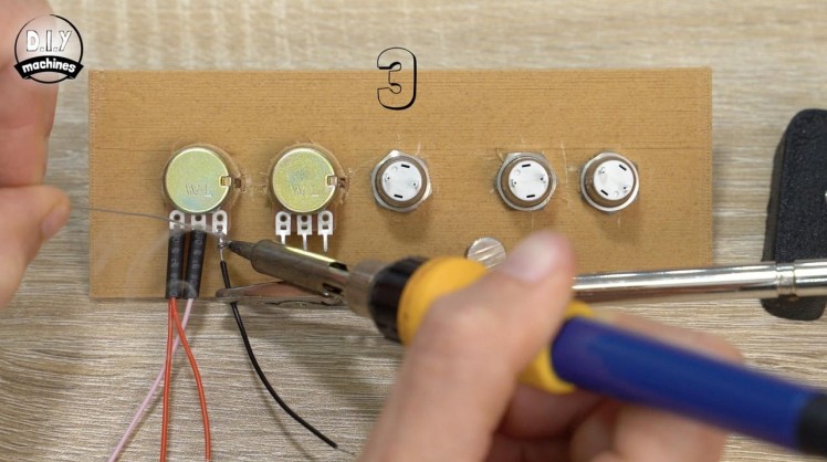
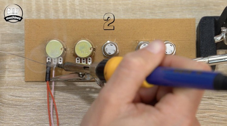
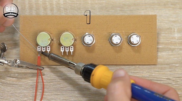
We can then turn the print around and begin attaching some wires. I will be using some lengths of heat shrink to help protect the connections, don’t forget if you’re doing the same to slide it over the wires before soldering them in place!
I have numbered the photos to match the corresponding numbered steps below to help you follow this step through.
Working from left to right with the potentiometers on the left, attach:
- A 30 and a 6cm wire to the first leg.
- A 30cm long wire to the second.
- A 6cm wire to the third.
- The fourth leg has the six cm wire from the first leg attached to it.
- The 5th leg has a new 30cm long wire attached.
- The 1st buttons leg has the 6cm long wire from the 3rd leg attached along with a new 30cm wire.
- The other leg on the first button gets a new 30cm wire.
- Each of the remaining unconnected legs have an individual 40cm long wire attached to them.
Well I got to the end of the control panel and then realised I was trying so hard not to make a mistake that I completely forgot to connect the 6th leg along. Let’s remedy this by:
9. Adding a short wire between the first buttons leg which already has two wires attached and...10. the unconnected 6th leg.
Once the heat shrink is shrunk the back of your control panel should look like the final photo.
Step 39: Connect Control Panel to CNC Shield
1 / 8
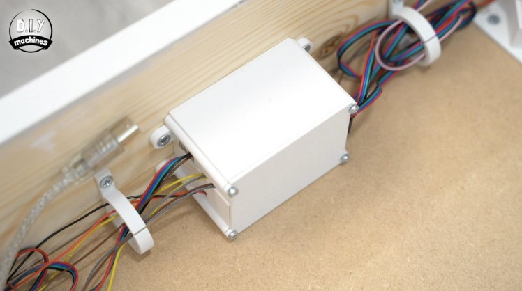
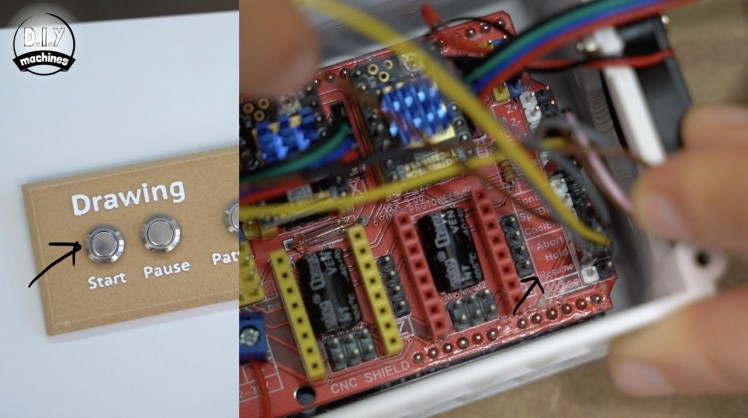
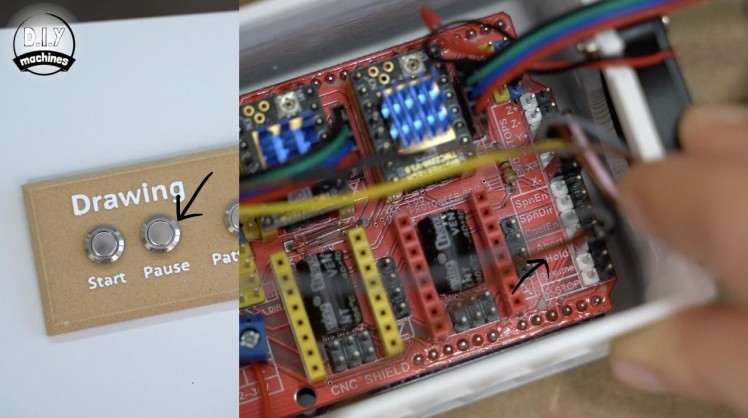
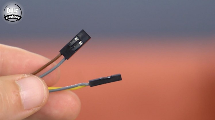
The first two buttons on the control for pausing and playing the sand patterns will be connected to our CNC shield. I added some Dupont connectors to each pair of button wires to make connection easy. I have made a separate tutorials showing you how to easily add them which you can find here:
Remove the lid on the CNC shield and optionally unscrew it from the table frame momentarily whilst we connect the wires for our control panel. It will make it easier to access the internals.
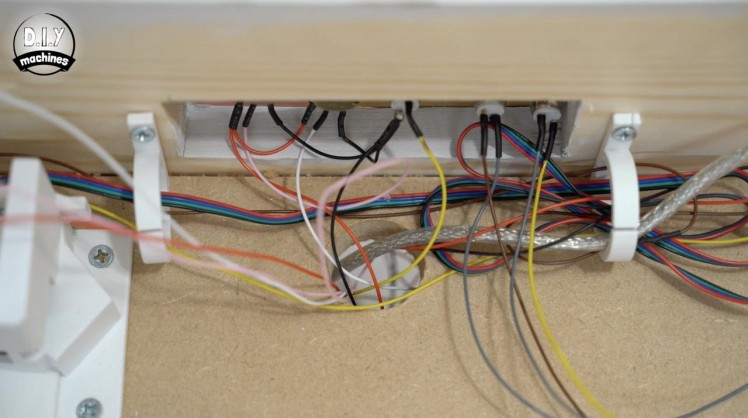
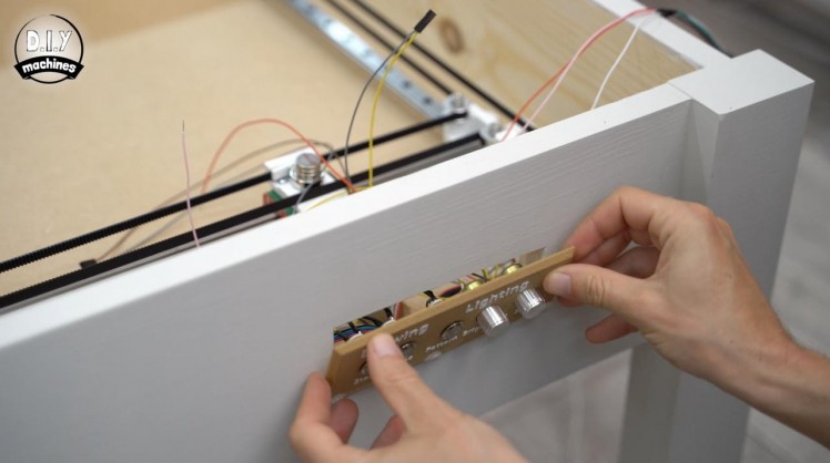
Pass the wires through the opening for the control panel from the outside of the table top. We won’t fit it in place just yet until we are sure our wiring works well after testing it later.
The two wires coming from the start button are connected to the pins labelled as 'resume' towards the bottom right of the shield, and the pair of wires for the pause button are connected the pins labelled as 'pause'.
The other bare wires coming from the control panel can be feed through the hole in the baseboard.
Refit the CNC GRBL electronics to the table frame with its lid attached. We will not need to access these electronics again.
Step 40: Mini360 Buck Converter Preparation
1 / 6
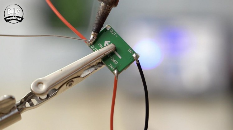
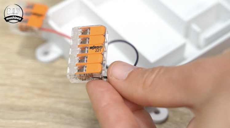
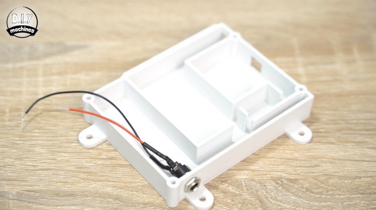
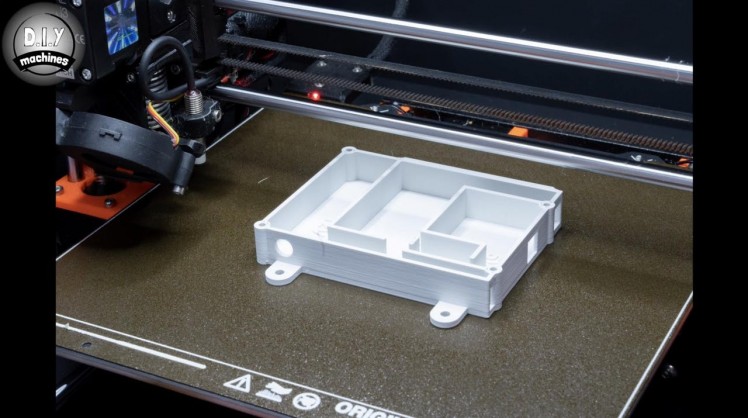

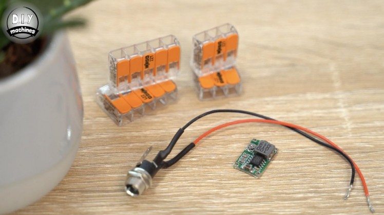
For this step you will need:
3D printed parts:
- PowerPanelCase.stl (x1)
Wago style connectors:
- 5 Way (x2)
- 3 Way (x1)
- Mini360 Buck Converter (x1)
- Some wire
To create the mix of 12v and 5v power levels our project requires we can set about assembling our power system. For this you will need your Mini360 buck converter, the barrel connector we prepared in the first video and the wago style wire connectors.
Trim the positive lead on our barrel connector to about 7cm long. The other we can leave at 12cm.
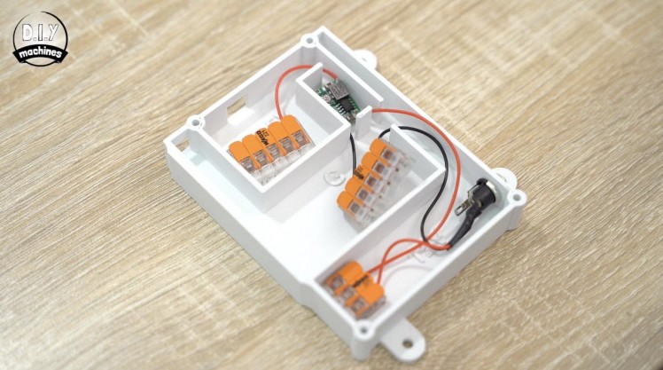
Thread the connector through the 3d printed housing and secure in place using its included nut. Attach a three way terminal to the 7cm long positive wire and a 5 way terminal to the ground wire.
Solder three lengths of wire to the terminals on the Mini360 buck converter. A 13cm wire to the positive input and a 5cm wire to the negative input. Finally a 6cm wire is connected to the positive output.
Step 41: Setting the Output of the Mini360
1 / 5
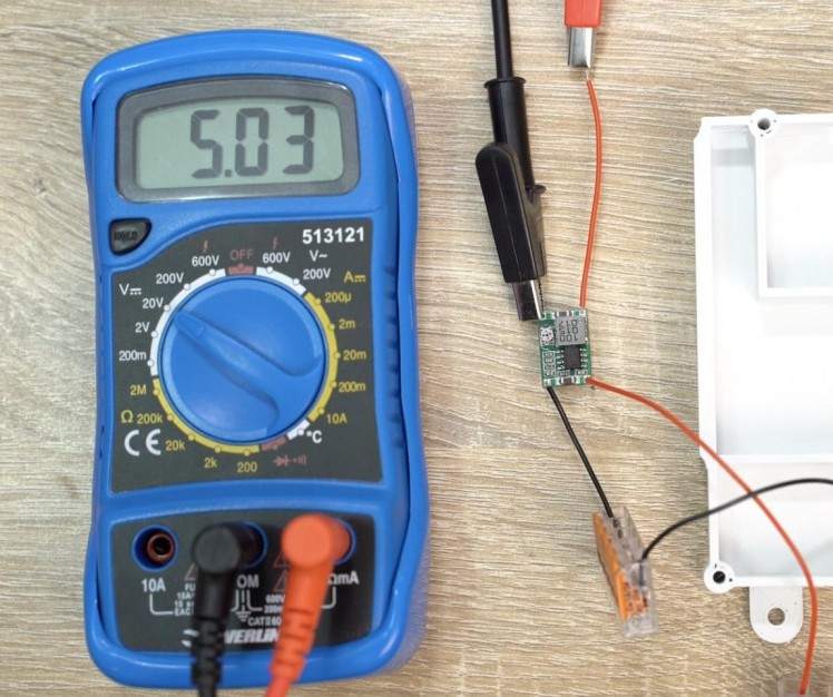
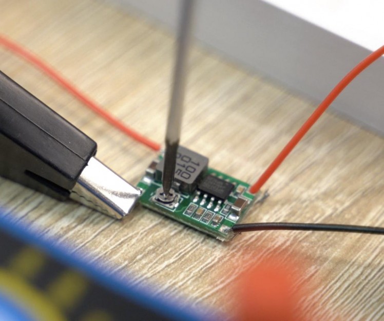
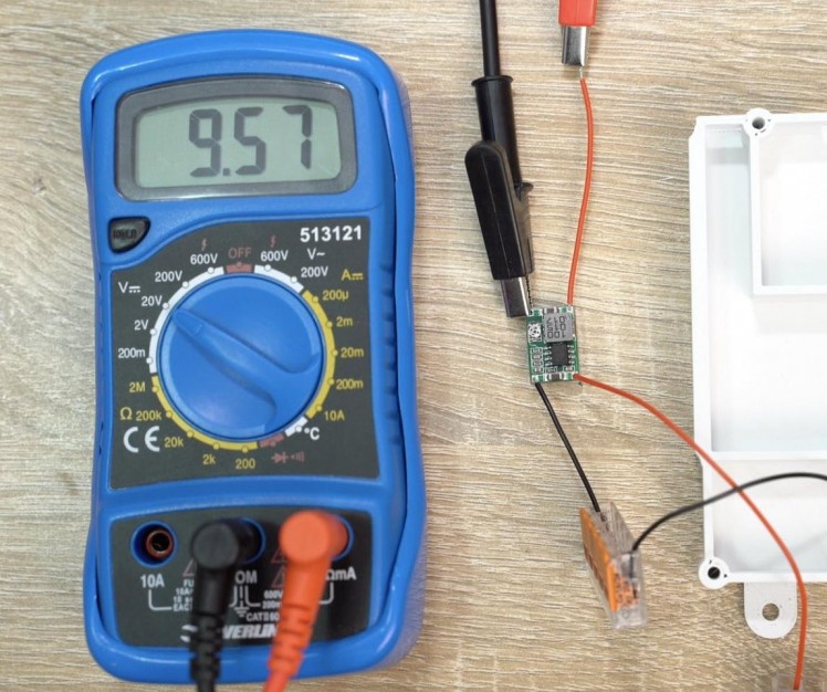
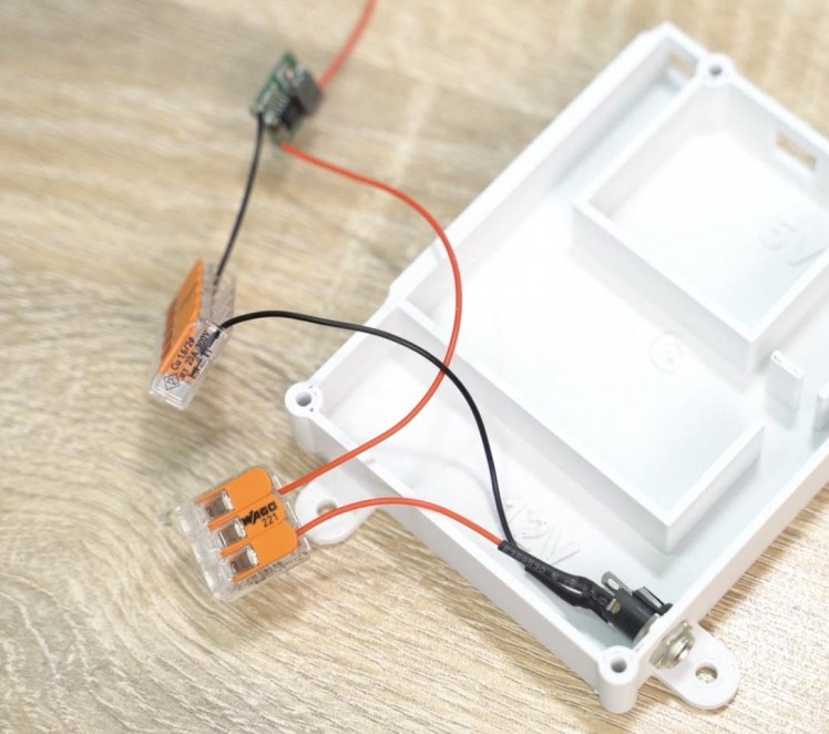
The Mini360 buck converter is capable of outputting a range of voltages so we need to set it to 5v before we can connect it to the rest of our circuit.
To do this we will connect it to the 12v power supply coming from our barrel connector and use a multimeter to measure its output voltage whilst adjusting its potentiometer.
Attach the multimeters positive probe to the positive out wire and the negative probe to the negative output terminal. Use a small screwdriver to carefully adjust the small onboard potentiometer whilst watching the output voltage on your multimeter. Aim for as close to 5v as you can. I settled for 5.03v. (Slightly over is preferable).
Once set we can disconnect the multimeter and power supply. The mini360 is then nestled into its own section of the 3d print. Once nested, add a five way terminal to its positive output.
Step 42: Attach the Power Panel
1 / 4
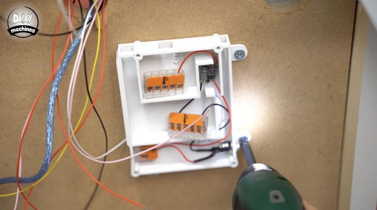
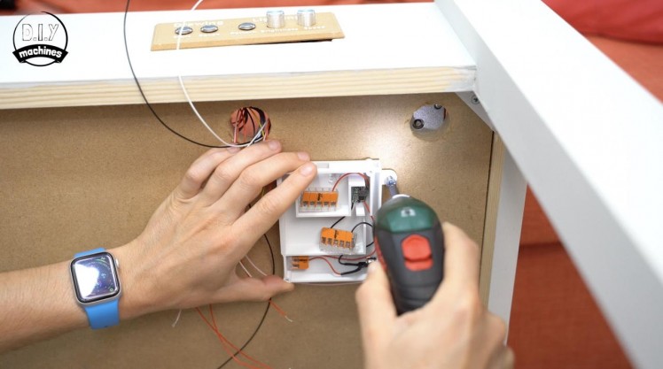
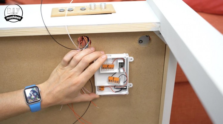
For this step you will need:
- Small wood screws (x3)
Now is a good time to fix this to the underside of our table frame. Make sure you remove the LED frame and 3mm baseboard with sand before you carefully place your table on its side with the control panel facing upwards.
Use three wood screws to install it towards the top right of the base so that the barrel connector is on the right hand side and the buck converter towards the top right.
Step 43: Wiring Power
1 / 10
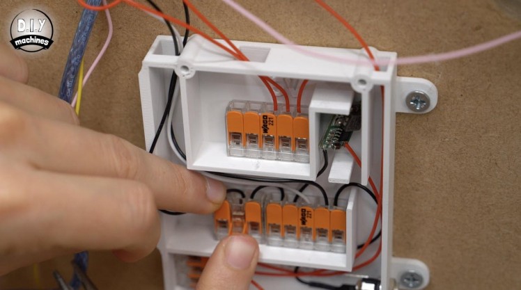
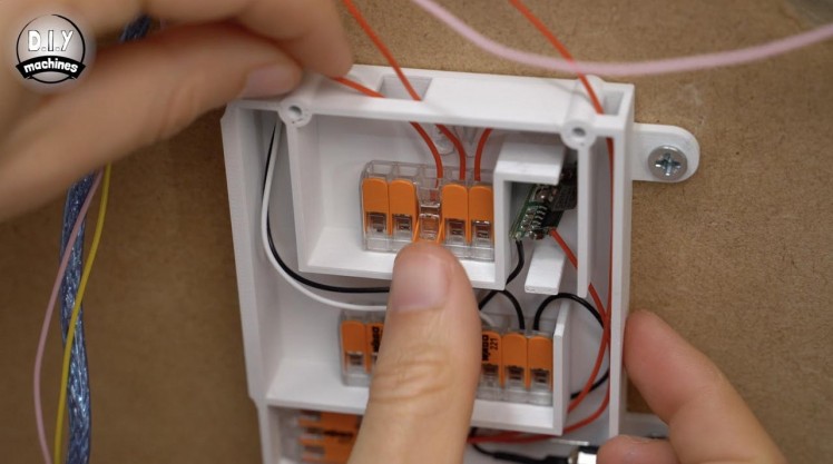
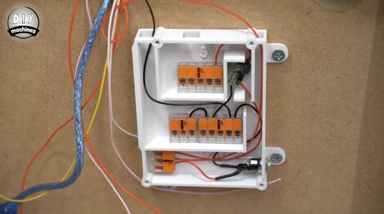
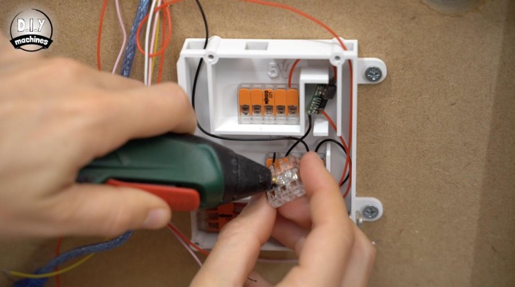
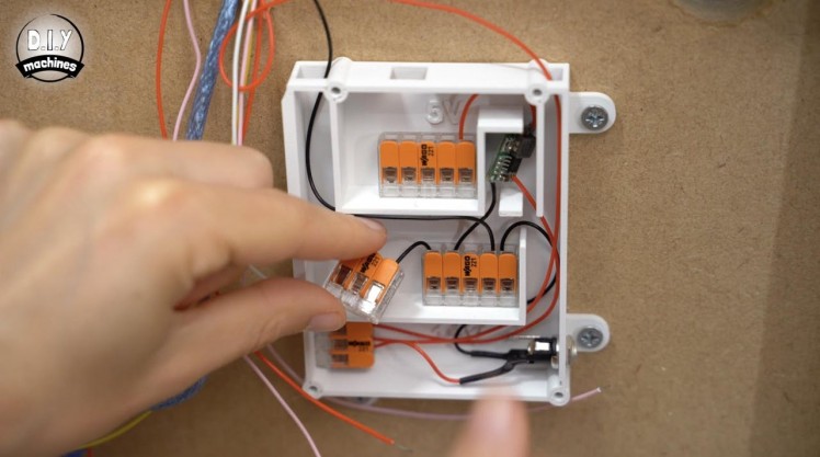
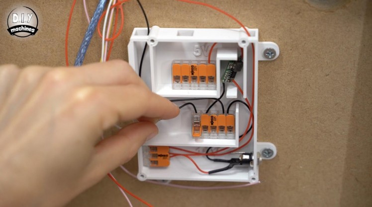
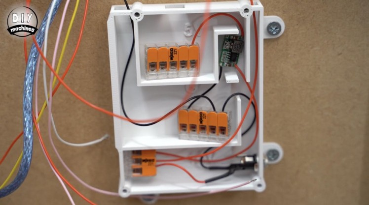
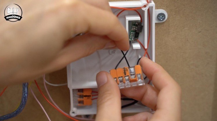
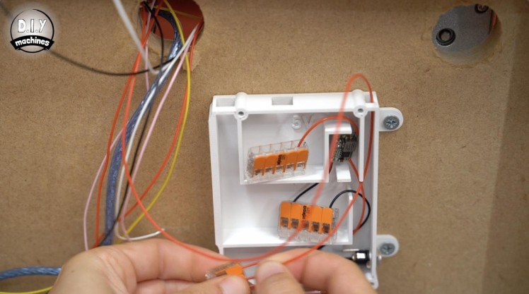
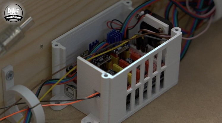
We can take the power wires coming from our CNC shield (brightest in the first photo) and connect the negative to the ground terminal and the positive to the 3 way terminal at the bottom which supplies 12v. You can trim the length of these wires and any of the others as we go if you find you have excess length.
We will require more than five ground connections so we need to cut ourselves a new 5cm long wire which we can use to join the current five way ground terminal to an additional three way connector.
To keep the connectors in place and tidy use some glue to pin them down and keep everything tidy. (7th photo)
We can now connect the power connections for our LED lighting. The wire you connected to the LEDs red wire is our positive lead and should be connected to the 5v connections the buck converter provides (9th photo). The wire you connected to the white lead is a ground connection so can join the other ground wires in the wiring block. (10th/last photo)
We also have a wire from the control panel to connect to the power circuit. This is the 30cm wire connected to the left most pin, which should be connected to the 5v power block.
Step 44: Arduino Nano Software
1 / 6
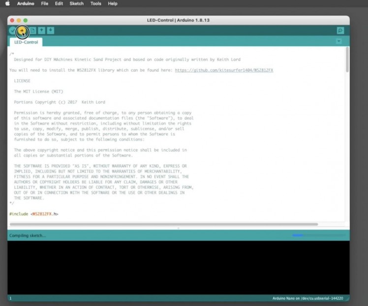

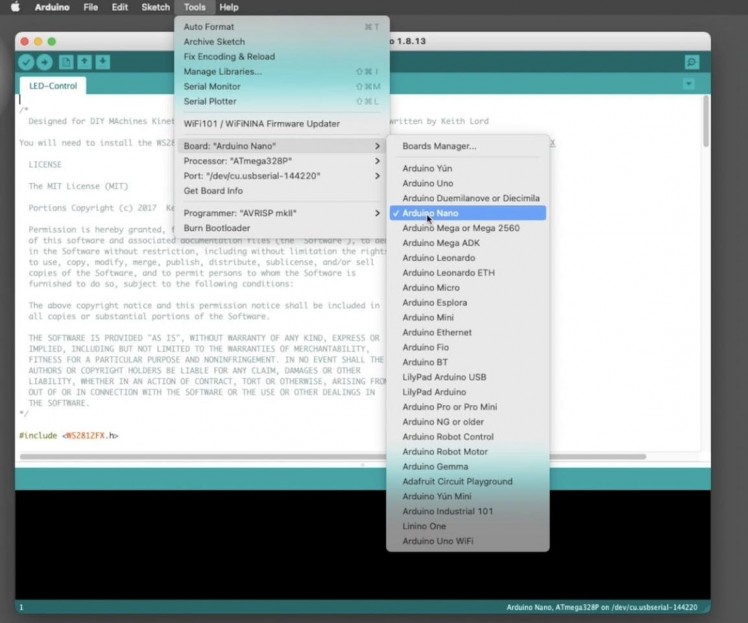
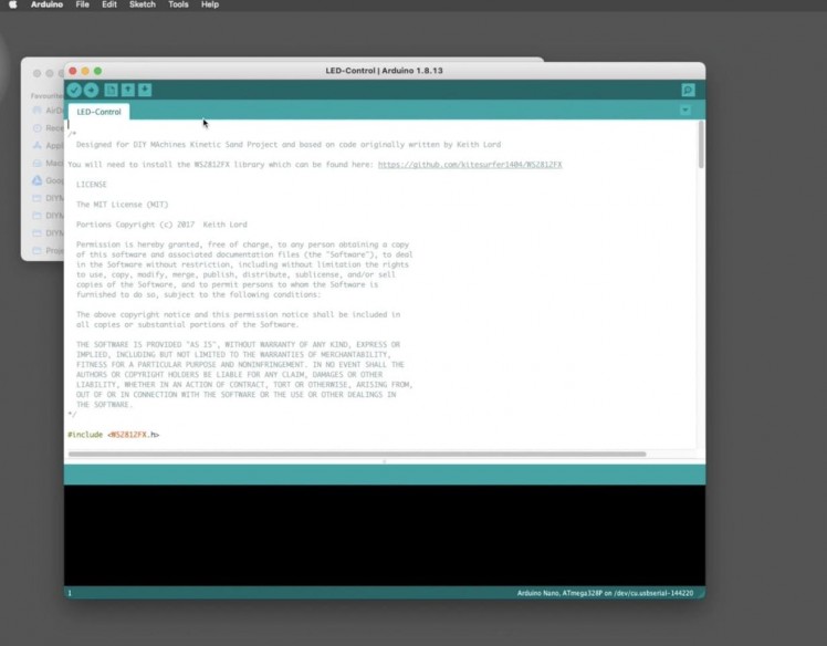
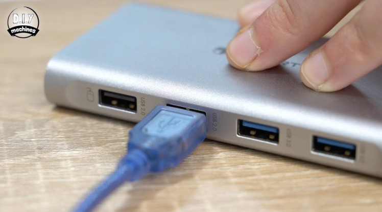
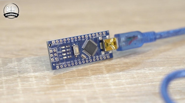
For this step you will need:
- Arduino Nano (x1)
- USB cable (x1)
- Arduino IDE (https://www.arduino.cc/en/software)
Next up we will install the Arduino Nano so we can light up the LED’s and put them and their related control buttons through a test. We will upload the code to the Arduino Nano first by connecting it to your computer with a USB cable.
Open the Arduino IDE and the code for this project. The code for the project can be downloaded from Github: https://github.com/DIY-Machines/Kinetic-Sand-Art-...
The code for the Nano is found inside the LEDArduino folder and is called 'LED-Control.ino'.
If you do not already have the WS2812FXlibrary installed you will also need to install it. It is free and can be found here: https://github.com/kitesurfer1404/WS2812FX The creators site also includes clear instructions on how to install the library if you are not familiar with doing this already.
Select the correct board type of ‘Arduino Nano' from the 'Tool' menu bar and the port for your device before pressing upload. Once the upload is complete we can disconnect the Arduino.
Step 45: Wiring the Arduino Nano
1 / 10
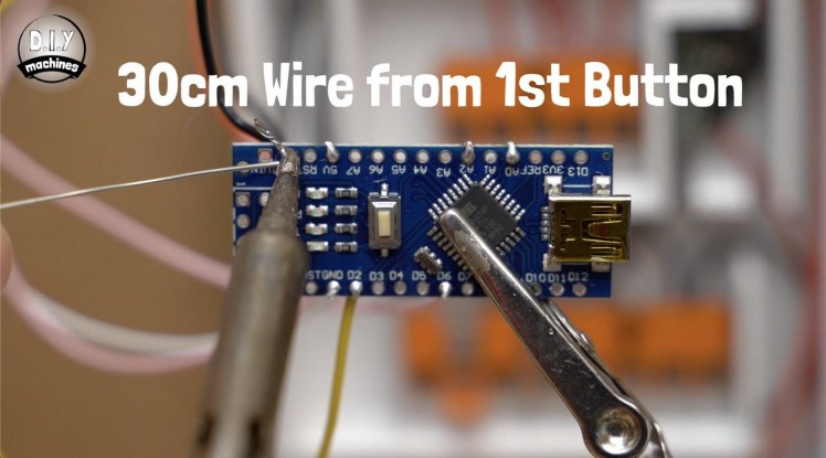
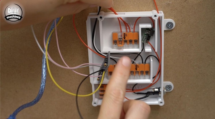
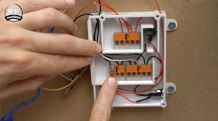
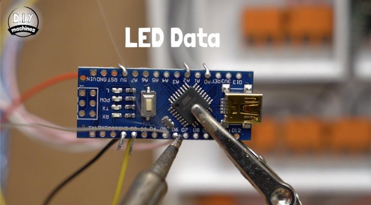
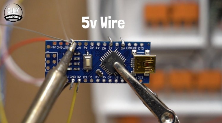
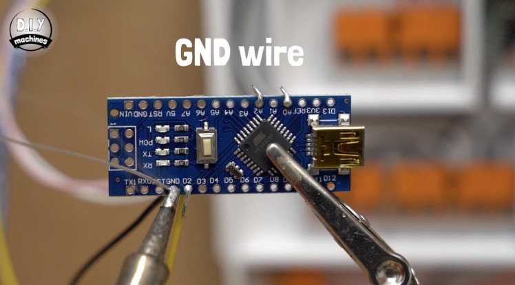

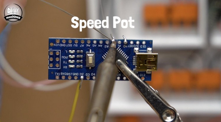
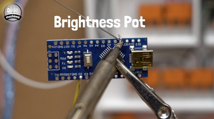
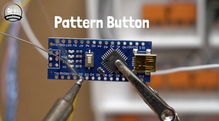
We can connect the wires from our control panels lighting section and the LEDs themselves directly to the Arduino by soldering them to the board. The Nano will reside on the underneath of our table so ensure that the wires pass through the baseboard holes before attaching them!
The single wire coming from the pattern button is soldered to pin D2 on the Arduino.
The central leg of the brightness potentiometer is attached to A0 and the central leg of the speed control is attached to A2.
Two new 16cm long wires should be attached to an unused ground pin and the 5v pin on the Nano. The data wire coming from the LEDs green data wire should be connected to D6 on the Nano.
The wire we connected to GND can be added to the power panels ground connections, and the 5v wire to the 5v power blocks. The last wire is the 30cm long one attached to the first button along with two other shorter wires. This should be connected to an unused ground connection on the Arduino.
Step 46: Testing the LEDs
1 / 4
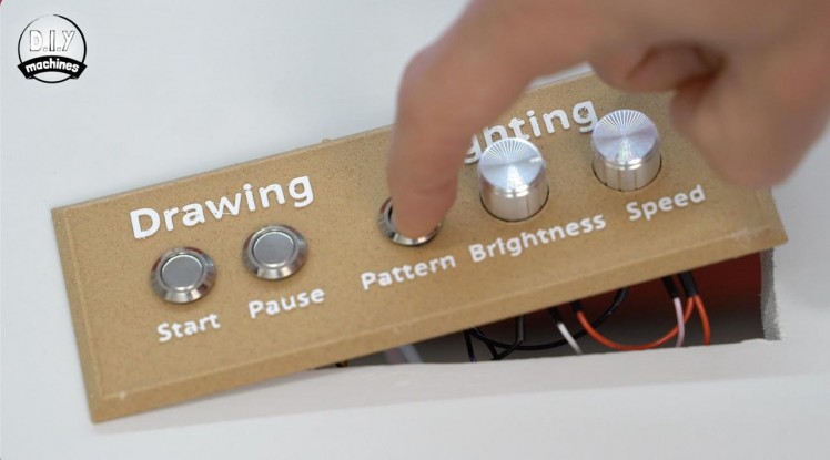
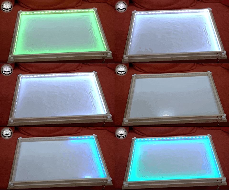
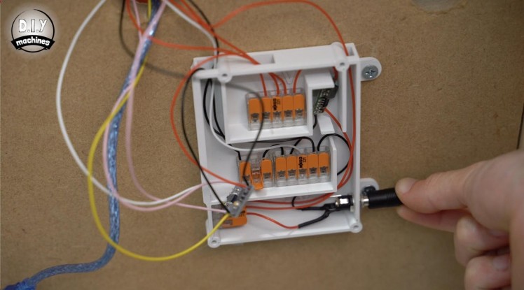
We should now be able to re-connect our LEDs and plug in the tables 12v power supply.
If all has gone as planned our LED’s should light up and you will have control of them using the control panel.
Pressing the pattern button should cycle through different lighting sequences, the brightness dial should adjust the brightness and the speed dial will effect the tempo of the patterns which are animated.
(Some of the patterns such as the 10th, a white one, are static so are not affected by the speed control.)
Step 47: Installing OctoPrint
1 / 12

For this step you will need:
- Micro SD card (8gb or greater x1)
- Raspberry Pi (x1)
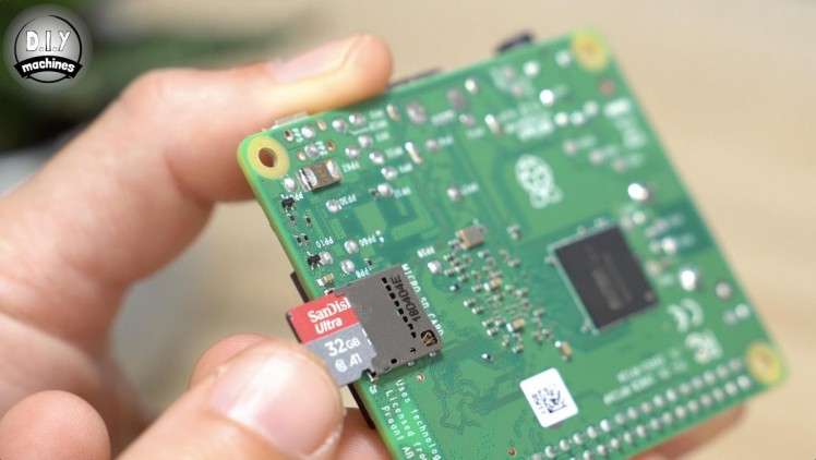
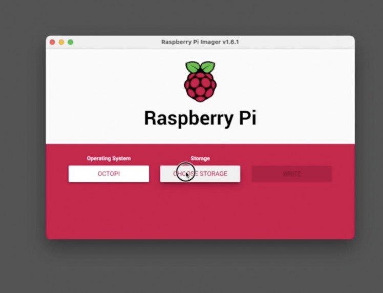
Let's add our Raspberry Pi next. The Pi will be responsible for feeding the GCODE instructions for drawing out our patterns to the Arduino line by line. To do this we will install OctoPrint onto our SD card. OctoPrint is primarily designed to control 3D printers - in fact I use it to control mine with great success. To make it more suitable for our sand table we will add some plugins and change a few settings.
I’ll explain how to do this now, but I also strongly encourage you to check the article for this project on my site - diymachines.co.uk for any revisions or improvements which may have been made since writing out this tutorial.
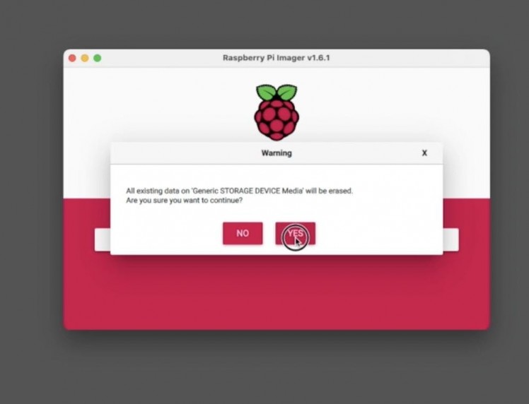
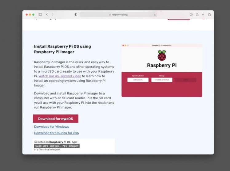
To flash the Raspberry Pi’s SD card we can use the Pi Foundations Raspberry Pi Imager. Head over to the Raspberry Pi foundation website ( https://www.raspberrypi.org/software/ ) and download the free imager from their software section.
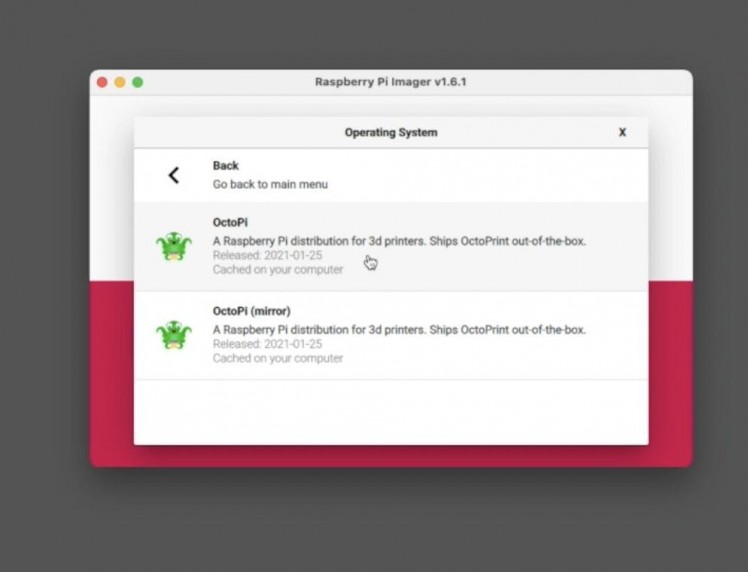
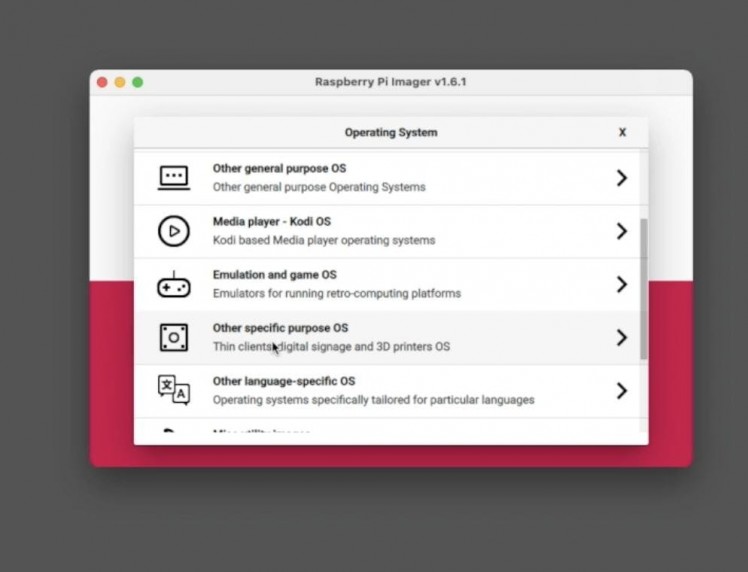
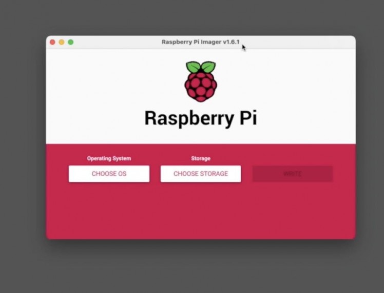
Connect your micro SD card to your computer and then open the Raspberry Pi Imager. Press ‘Choose OS’ then ‘Other specific purpose OS’. In this list you should find ‘OctoPi’.
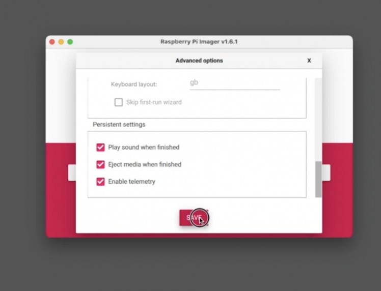
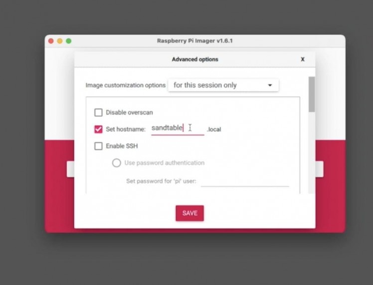
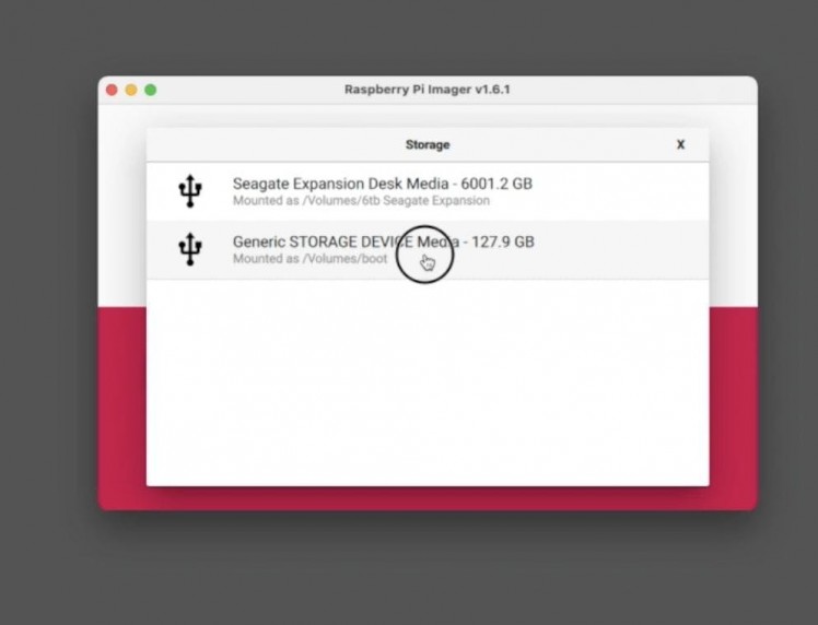
Continue on to select your SD card. Press the key combination of ‘Ctrl-Shift-X’ to access advanced menu.
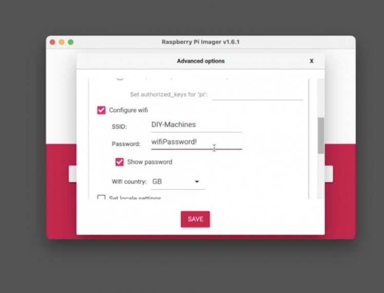
Check ‘set hostname’ and set one. I chose mine as sandtable (we will use this as URL to access the tables web interface later instead if an IP address). Then scroll down to configure your wi-fi credentials.
We can then press 'Save', then ’Write’. It may take a little time to download the image, flash it to your card and then verify it. It’s a great opportunity to make a lovely cup of tea.
When that is complete we can remove the SD card and insert it into our Raspberry Pi.
Step 48: Fitting the Raspberry Pi
1 / 8
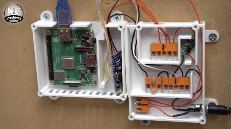
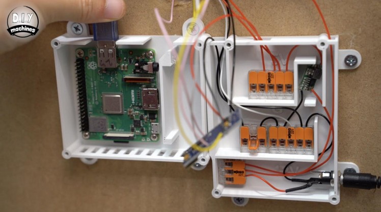
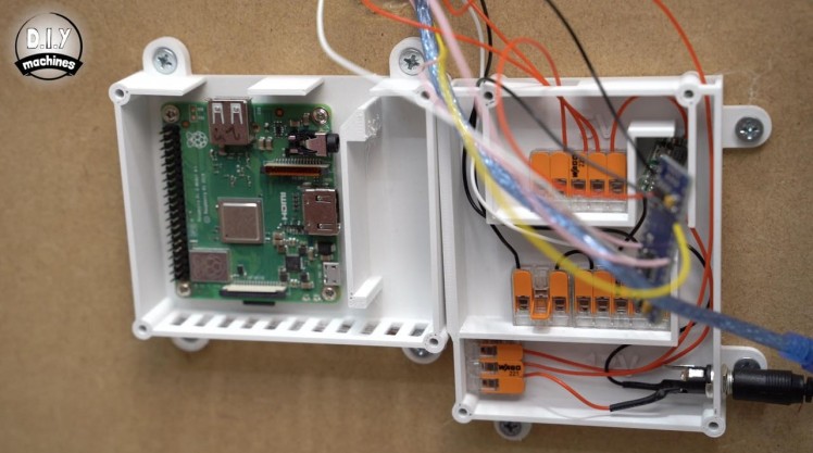
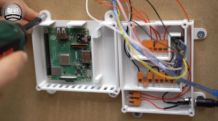
For this step you will need:
3D printed parts:
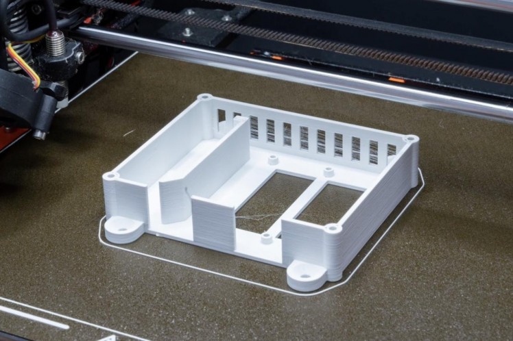
- ComputingCase.stl (x1)
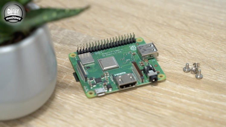
- 2.5mm screws (x4)
- Short wood screws (x4)
- Screwdriver
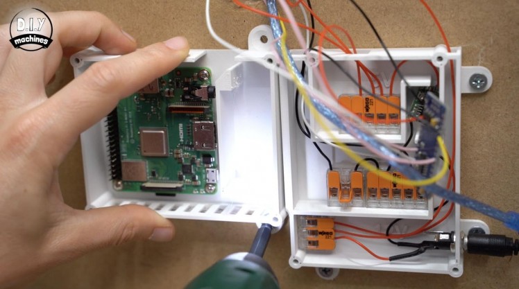
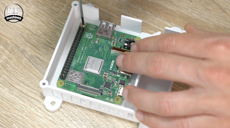
To fit the Raspberry Pi to the underside of our table we need to print the ComputingCase. The Pi is then secured on the plastic printed standoffs (integral to the case) with our four m2.5 bolts.
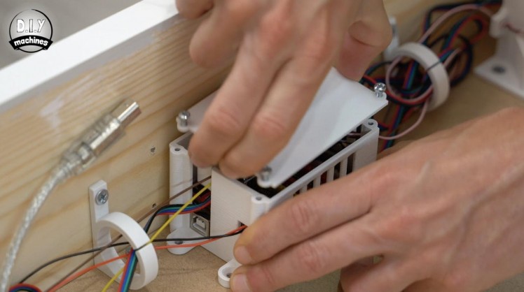
This is then secured with four wood screws up against the power case with the two side cut outs towards the top.
The USB port should be facing the cutouts so we can now connect the USB cable.
Step 49: Power to the Pi!
1 / 7


For this step you will need:
3D printed parts:
- ComputingLid.stl (x1)
- Dupont style connector
- Some wire
- M3x8 bolts (x4)
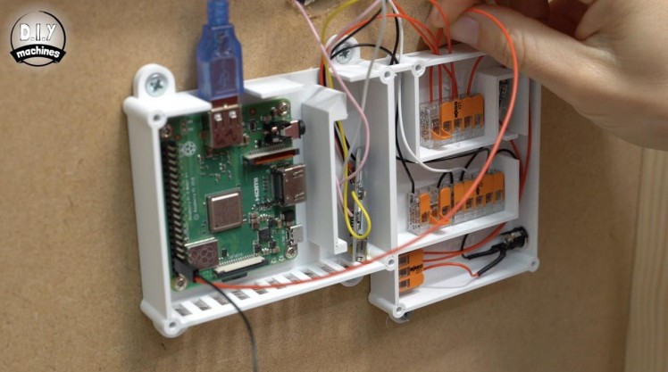
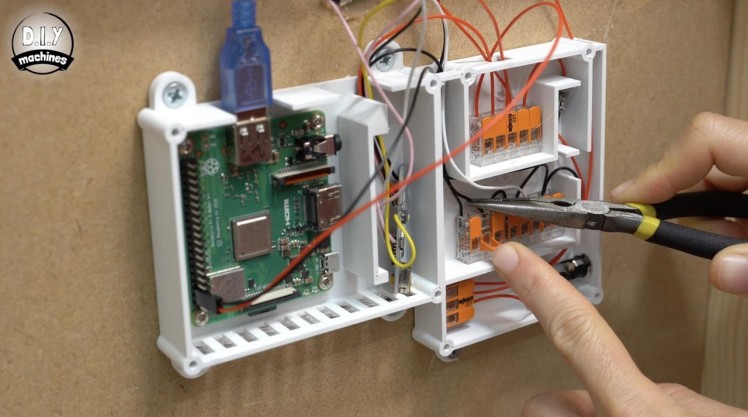
Prepare two new wires, one 28cm long and another 24cm long. These will be connected to the 5v and ground pins on our Pi to power it. As the Pi has pins already installed I have connected my two wires to a Dupont style connector.
The longer 28cm wire should be connected to the 5v pin (which is the second pin up from the bottom left) and the adjacent wire goes above this so as to connect to the ground pin.
The other ends of the wires are then connected to the respective power blocks. The longer wire joins the other 5v wire, and the shorter wire to our collection of ground wires.
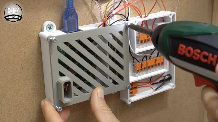
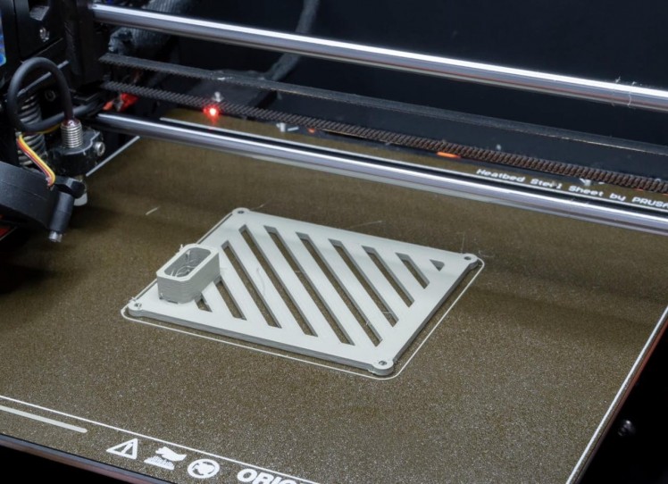
The lid for our computing case can be printed and then, after nestling the Arduino Nano in the second half of the case, we can fit the lid using four M3 bolts.
Step 50: OctoPrint Wizard Settings
1 / 14
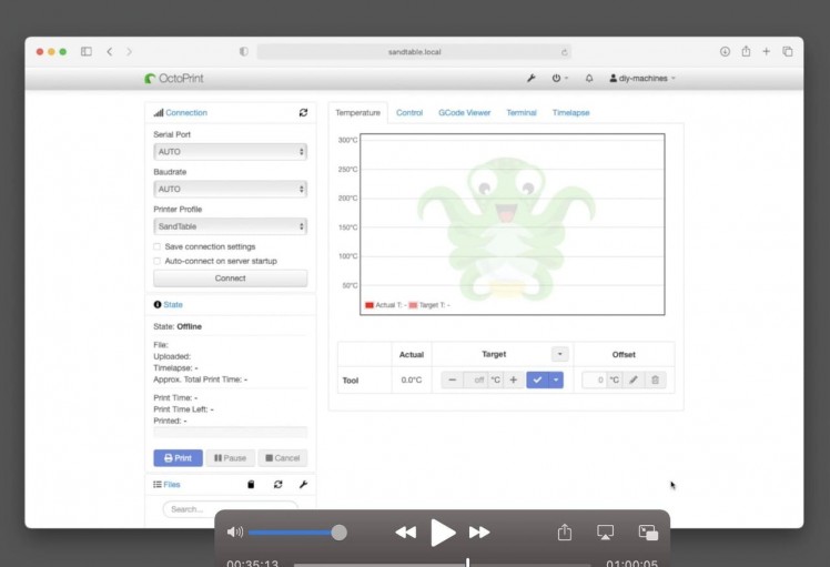
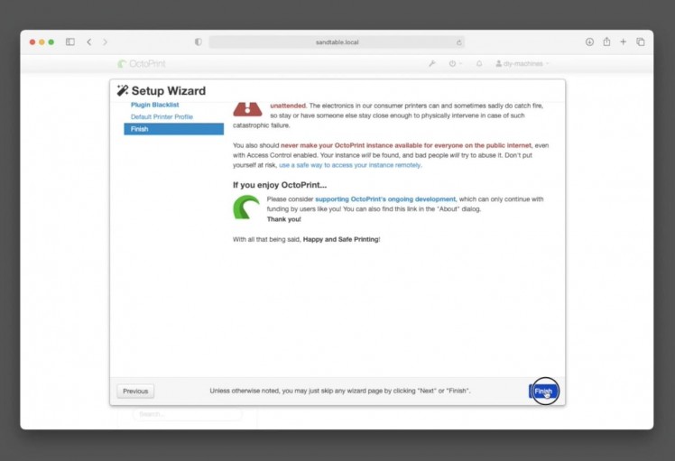

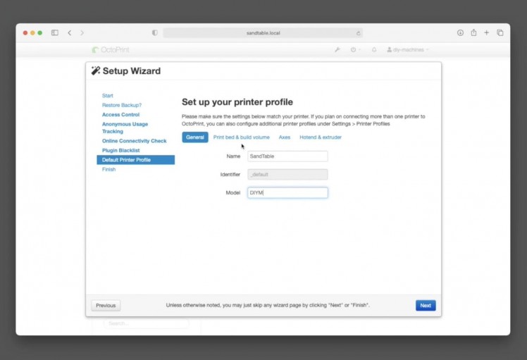
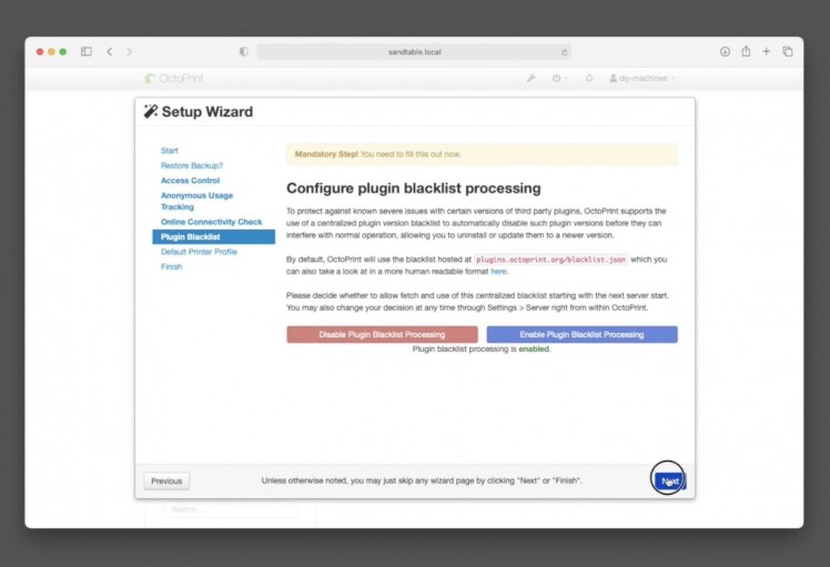
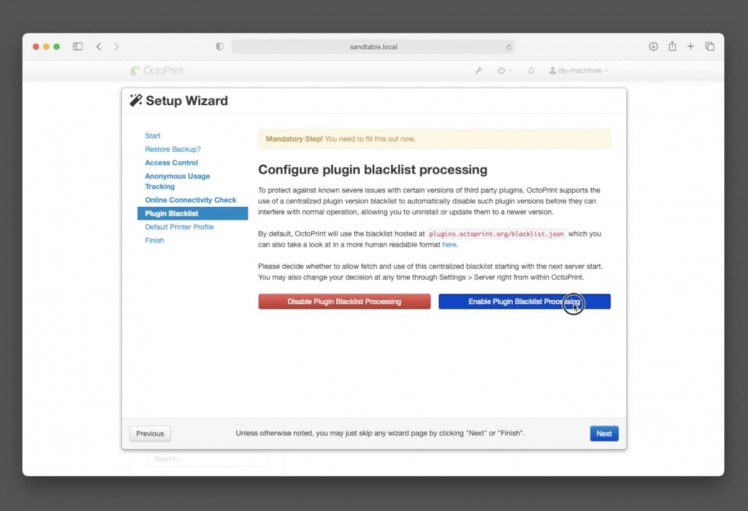
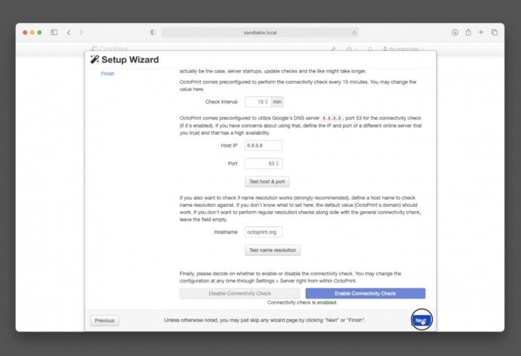
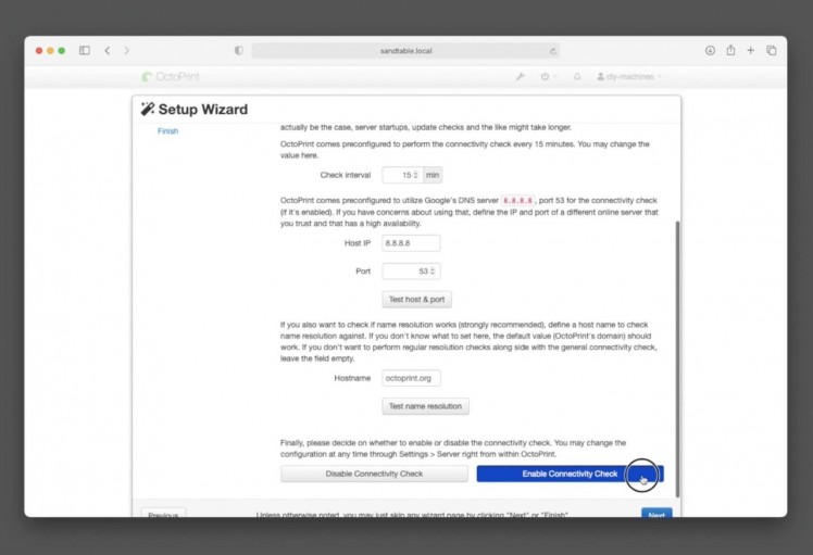
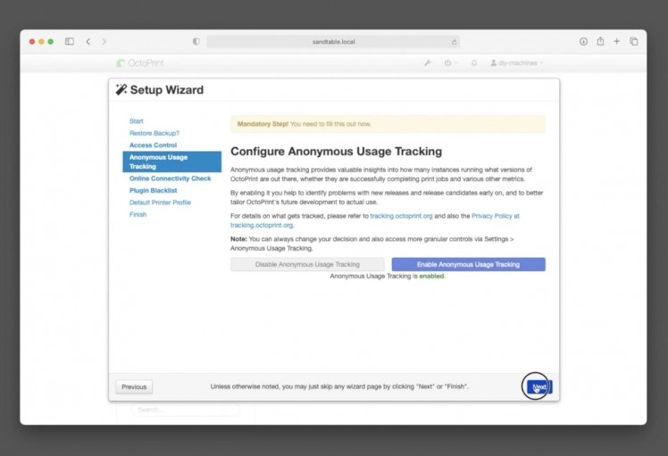
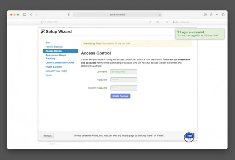
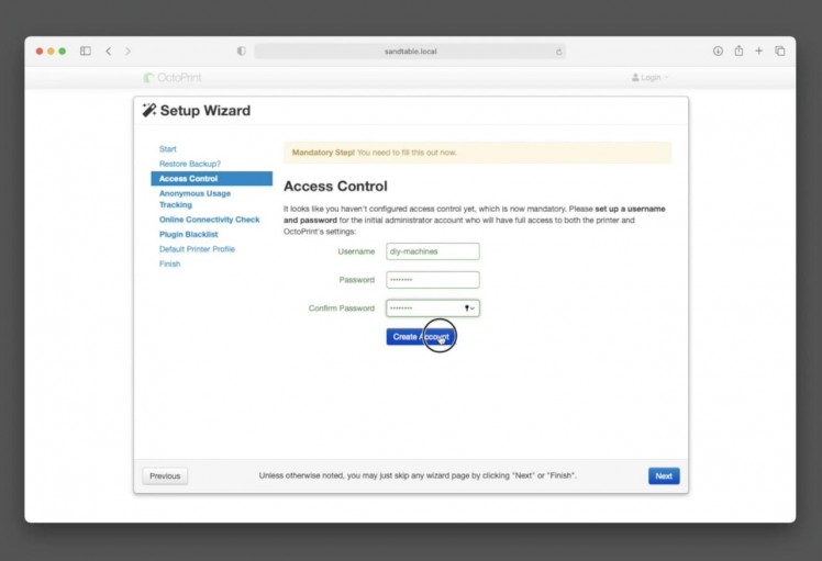
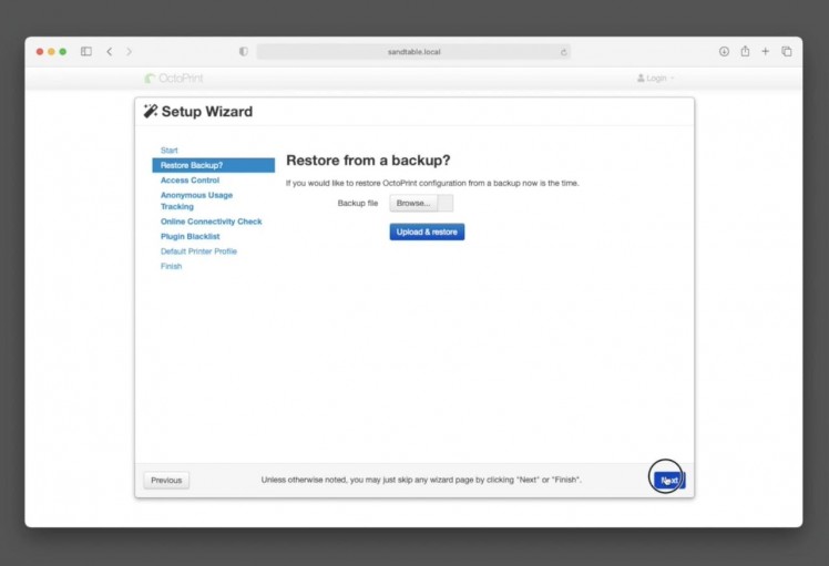
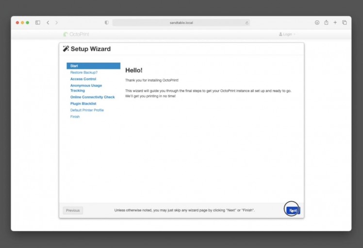
Connect the 12v power supply for the table and switch the power on. You should see the LEDs light up on the Arduino Nano and Raspberry Pi. Wait a couple of minutes for the Pi to finish its initial boot up and then navigate to sandtable.local in your web browser.
We will be presented with the OctoPrint Wizard. As mentioned earlier this is designed with the expectation that we will using it to control a 3D printer so some of the steps will be irrelevant to us. Let's fly through configuring the wizard now:
Finally at the 'Default printer profile' settings: Set the print volume to:
- X=525
- Y=330
- Z=10mm.(Don’t forget that if you have made your table larger or smaller than the one I am building in this video, you’ll find instructions on what settings need adapting and how for OctoPrint and GRBL on my site.)
- For name I entered ‘SandTable’
- Model = 'DIYM'
- Under ‘Print bed and build volume’ uncheck ‘Heated bed’
- At the 'Start' page: Just press next
- At the 'Restore Backup?' page : Just press next again
- At the 'Access Control' page: Choose a username and password which you will be asked for when connecting to Octoprint to control your table in future. Then press 'Create an account' and then ‘next’
- At the 'Anonymous Usage Tracking' page: Choose whether you want to disable or enable the tracking and then press ‘next’
- At the 'Online connectivity check': Choose to enable it and then press next.
- At the 'Plugin blacklist' options: choose 'Enable' and then next.
Step 51: Installing Plugin: Better GRBL Support
1 / 8
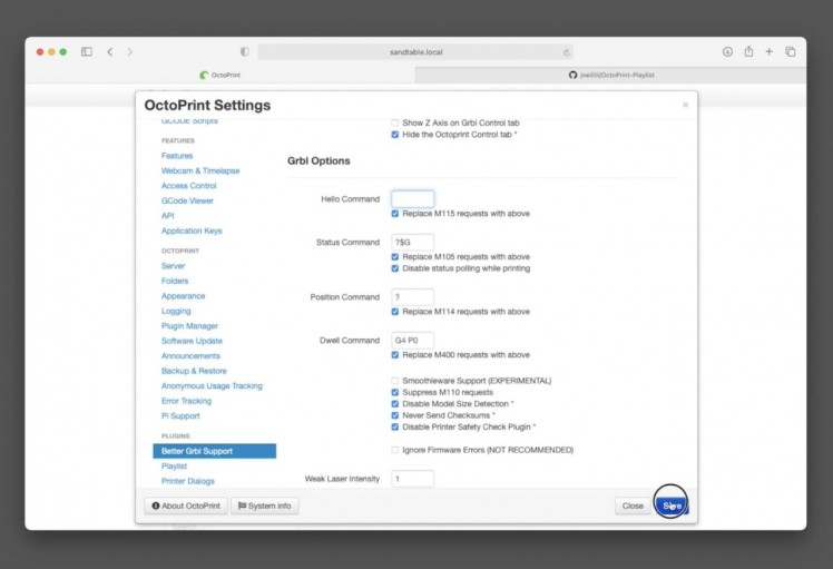
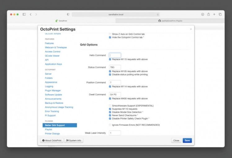
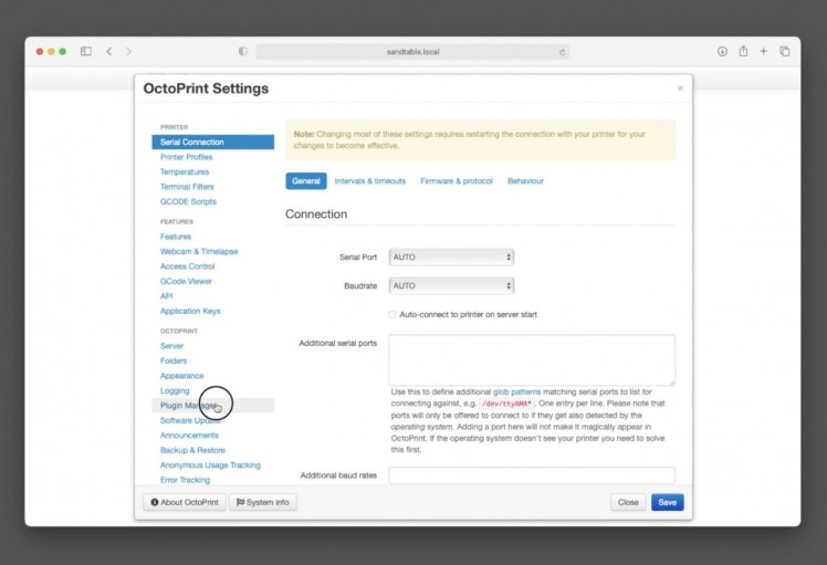
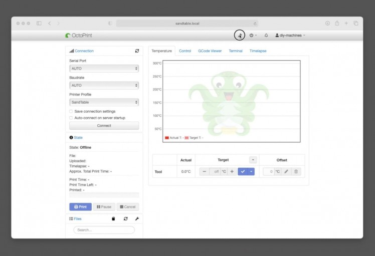
The first plugin to install gives us better control of GRBL. It's called 'Better GRBL Support' - great name huh. :)
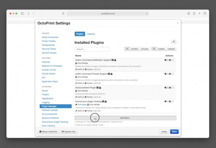
To install it click on the wrench icon in the top toolbar of OctoPrint, then ‘Plugin Manager’ from the menu on the left.
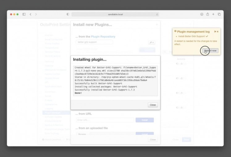
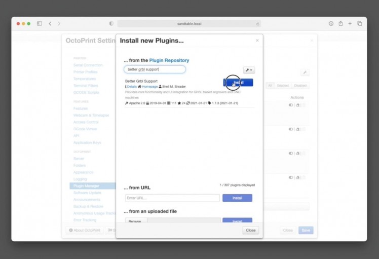
Click ‘Get more’ and search for ‘Better GRBL Support’ and click to install it. Restart OctoPrint. Simple as that.
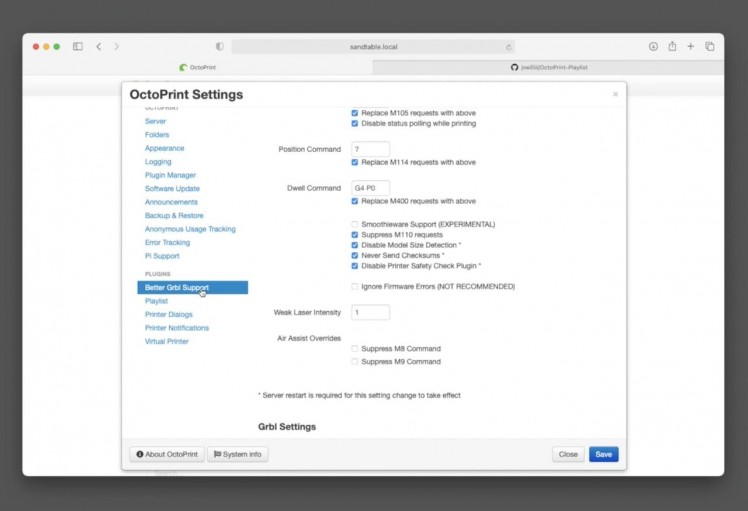
Actually, there is one setting we need to change for this plugin, open OctoPrint's settings page again, choose 'Better GRBL Support' from near the bottom of the left hand menu and then change the value of 'Hello Command' to blank (instead of the default '$$").
Step 52: Installing Plugin: OctoPrint Playlist
1 / 7
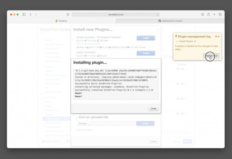
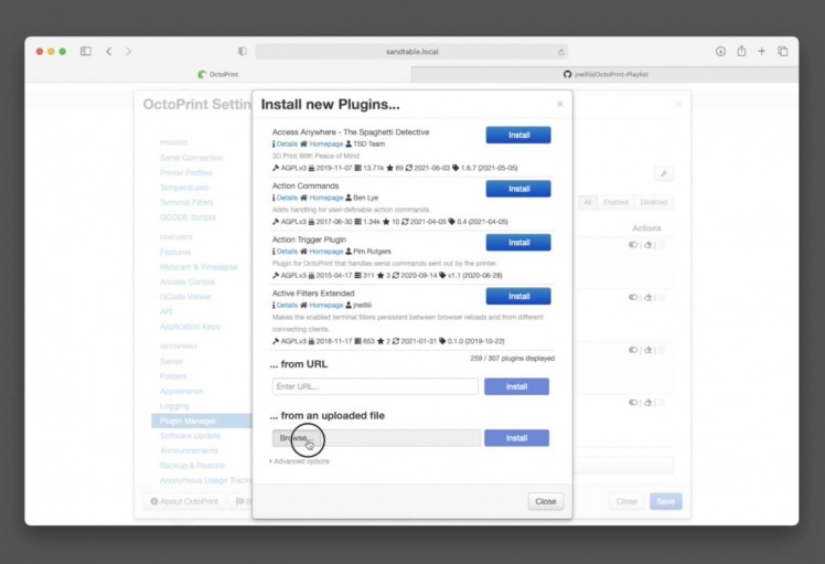
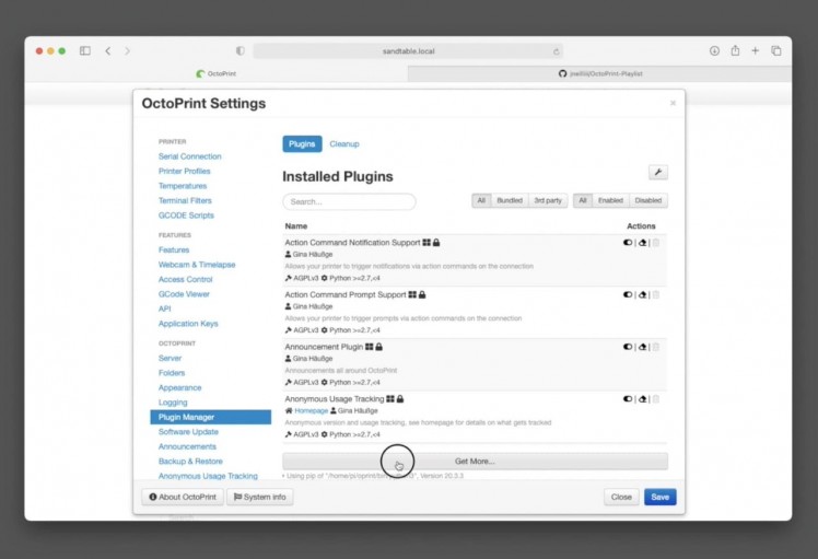
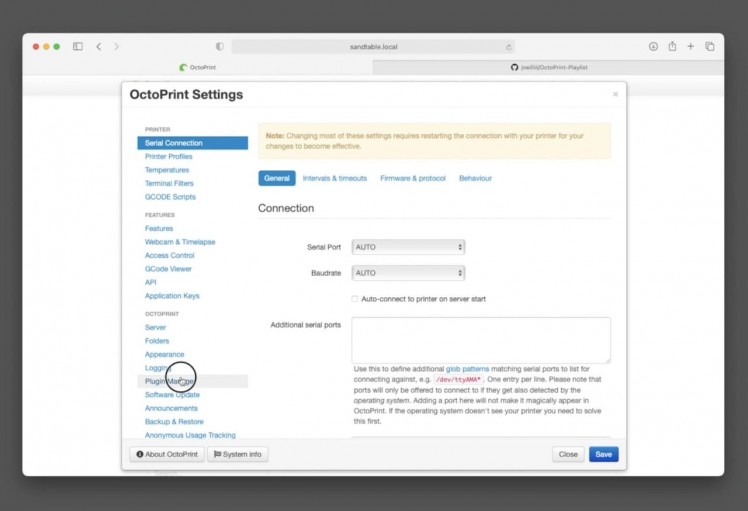

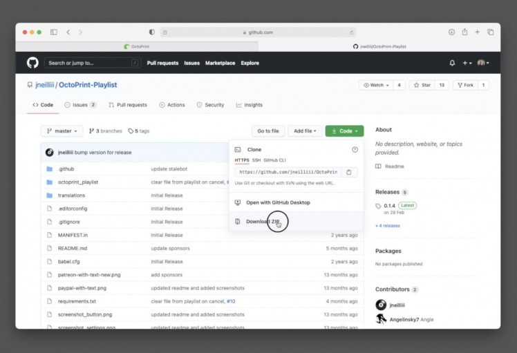
After restarting we can install the second plugin, OctoPrint Playlist. This will allow us to cue up a playlist of patterns and have our machine automatically move from one to the next on an ever repeating loop.
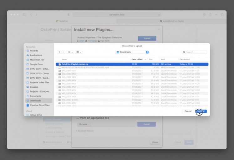
This Plugin does not reside in the official OctoPrint plugin service so we will need to download it from Github and upload it to OctoPrint.
Navigate to https://github.com/jneilliii/OctoPrint-Playlist click 'code' followed by 'Download ZIP'.
To upload this is OctoPrint click on the wrench icon at the top again, and re-open the plugin manager.
At the bottom of the window press the 'Browse' button underneath '....from an uploaded file'. Browse to the ZIP file you just downloaded from Github and upload it. Press 'Install'. OctoPrint will automatically check it and then proceed with the install before requesting a restart, which you should do.
Step 53: Completing the Control Panel
1 / 8
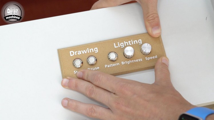

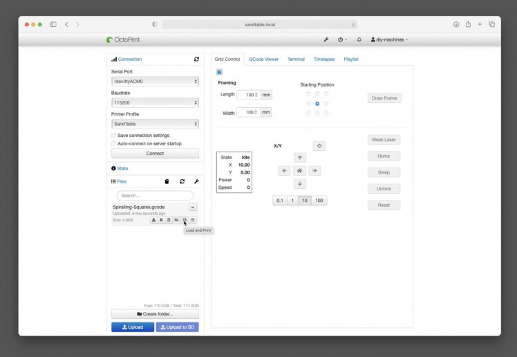
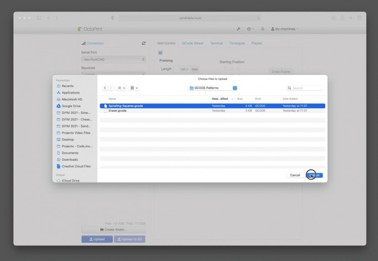
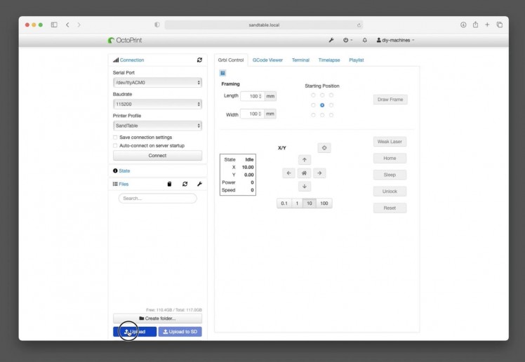
Let’s finish our work on the control panel. Before we fit it in place we need to finish checking all of the controls work, we have already checked the LED portion, so let’s test the Start and Pause buttons. This will also involve having our table draw out its first complete drawing in the sand. :D
To test the play and pause buttons for the GRBL electronics we will first start our machine drawing, and for this we will need an illustration which has already been converted to GCODE. I have included a couple in the files you downloaded from Github earlier, so let’s upload one to OctoPrint now.
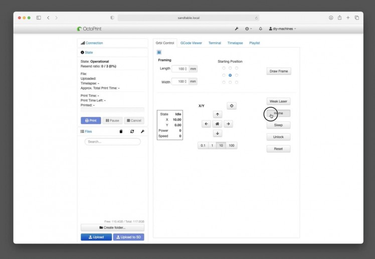
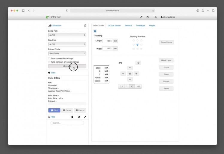
Open OctoPrint and then in the left hand column press upload. Navigate to the drawing file called SpriallingSquares.gcode and upload it. Before we can have the machine carve out the pattern we need to connect to GRBL and home the mechanism. Press ‘Connect’ on the left, if this does not connect first time, you may need to try again. Once connected, choose ‘Home’ in the GRBL control window.
Once the homing sequence is complete, and your sand surface and ball are fitted. We can press ‘Print’ next to our GCODE file to have our machine draw out the pattern. Whilst the machine is drawing we should be able to press ‘Pause’ and see the machine gently come to a halt, and then pressing ‘Start’ should cause it to resume.
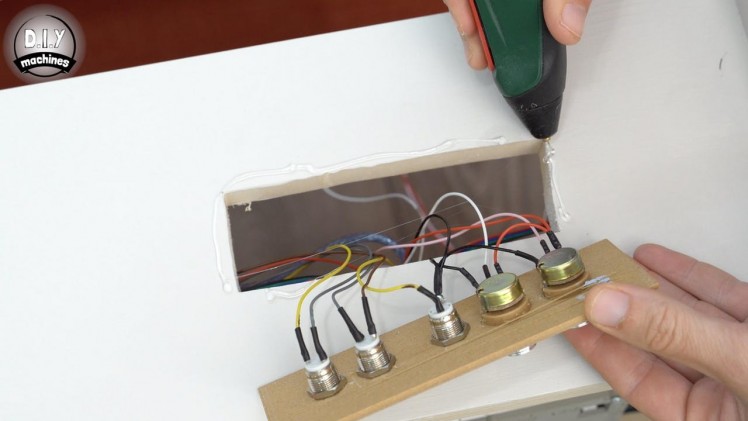
Now we know the control panel works we can fit it into place. I used glue to secure mine in place. Don’t forget to check your wires on the inside of the table are still securely held out of the way of the mechanism.
Step 54: Cutting the Table Top
1 / 5
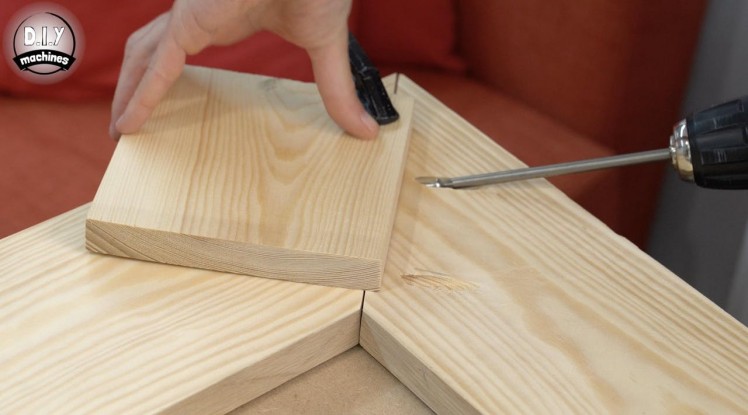
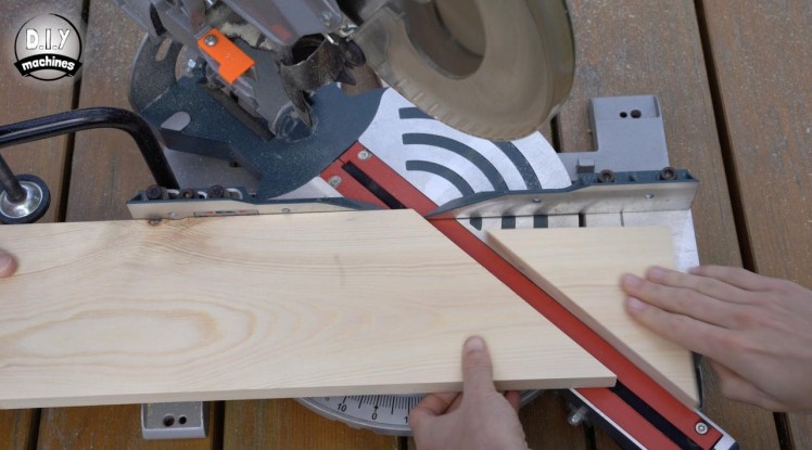
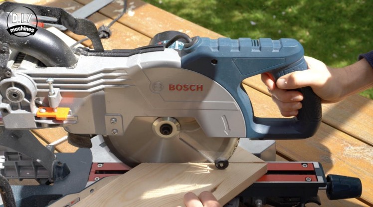
We are now very near the end of our project. We’ll make the top of our table now by mitring four panels of pine to form a border. I’ll be applying some real wood veneer and edging to mine before finishing with boiled linseed oil, you could do the same or paint it depending on your preference. Then a sheet of toughened glass is placed on top to turn this project into a centrepiece fit for the living room.
For the mitred panels I prepared two lengths of wood 683 x 170mm in size and two lengths 883 x 170mm. Both ends of all four panels were then mitred at 45 degrees using my mitre saw.
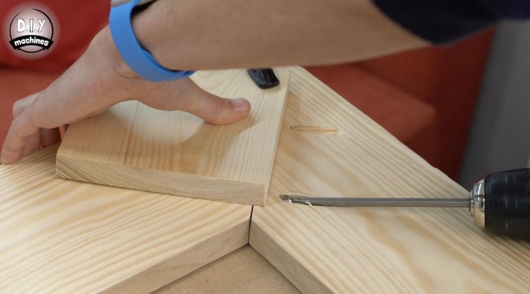
I then used pairs of pocket holes drilled into the ends of the long panels to assemble them together. Once I was happy with the fit I disassembled the panels so that I could veneer them individually.
Step 55: Preparing the Veneer
1 / 9
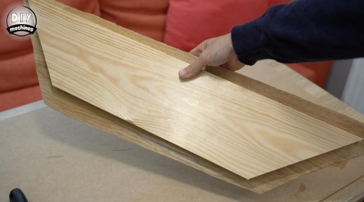
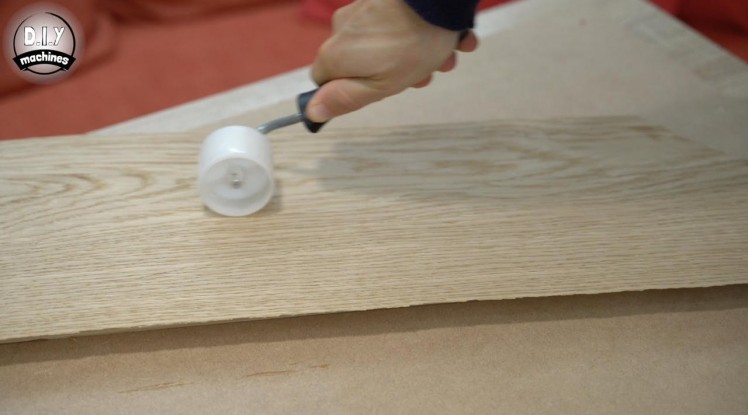
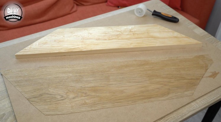
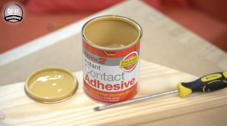
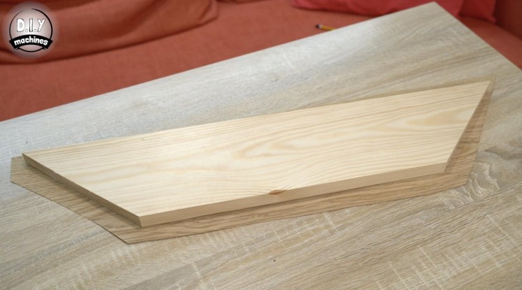
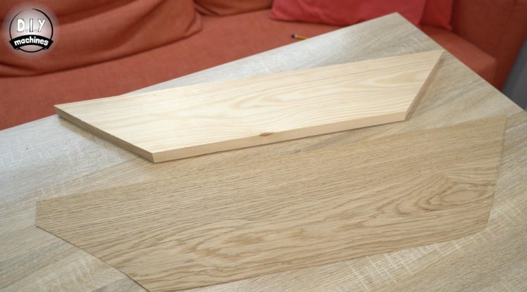
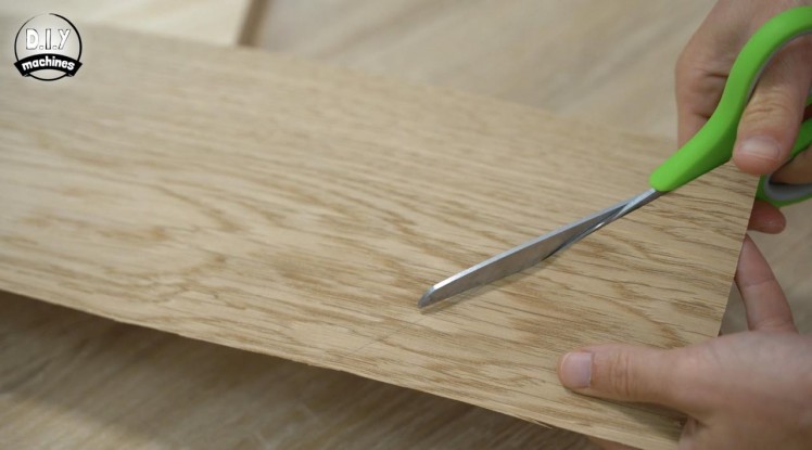
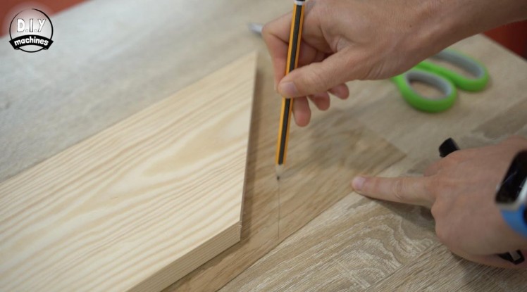
For this step you will need:
- Wood veneer (enough to cover the panels)
- Contact adhesive
- Roller (to apply pressure)
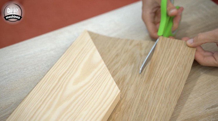
Now I’m no woodworking expert, but I will explain to you how I went about veneering my panels.
I chose to use some European oak veneer which I got from Oakdale Crafts here in the UK. (https://oakdalecrafts.co.uk) I cut some lengths slightly larger then each of my panels and then applied some contact adhesive to the panel itself and then rear of the veneer. Once this dried (after about 30 minutes) I brought them together carefully and used a small roller to apply a lot of pressure to ensure a good adhesion.
Step 56: Trimming Veneer
1 / 6
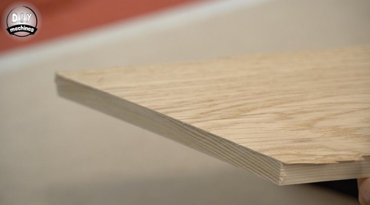
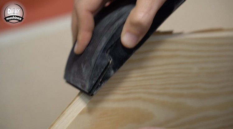
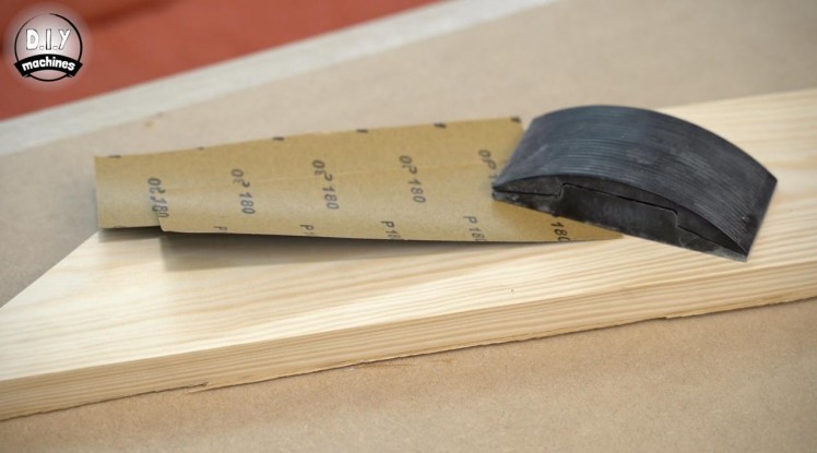
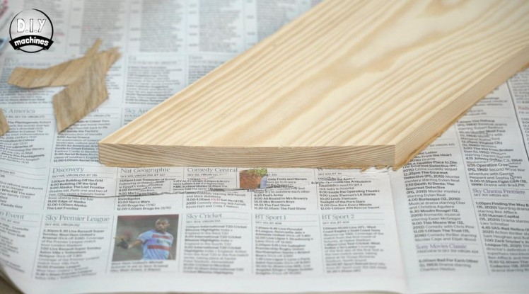
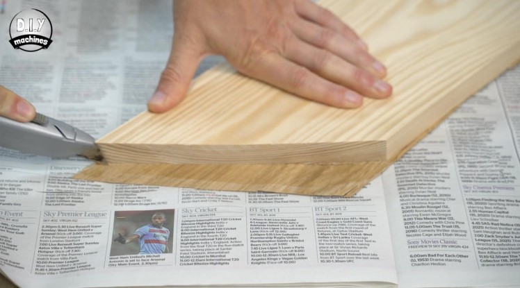
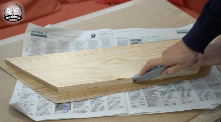
For this step you will need:
- Sandpaper
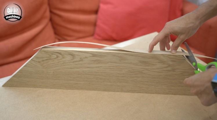
- Stanley knife
A sharp knife was then carefully used to trim off the majority of the excess before using some sand paper to carefully further refine the edges.
The last photo shows the short edges once completed. Repeat this on all four edges of each panel.
Step 57: Applying Interior Edging Strips
1 / 7
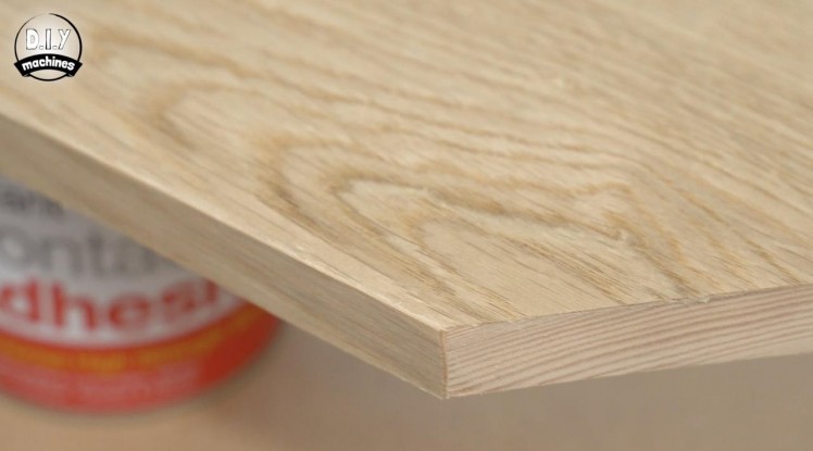
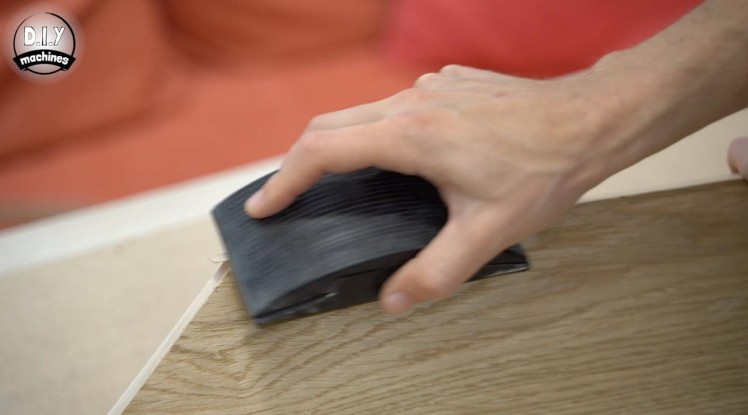
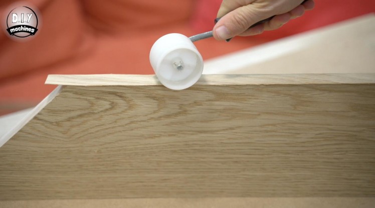
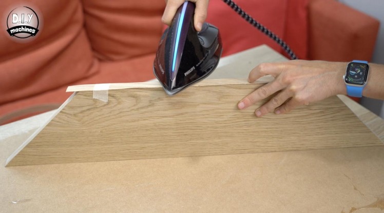
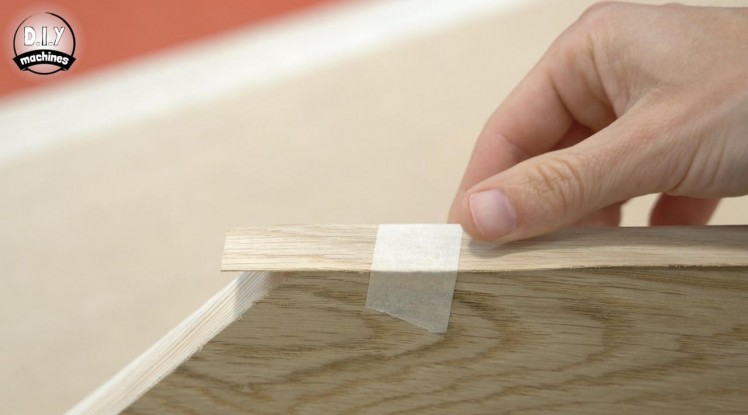
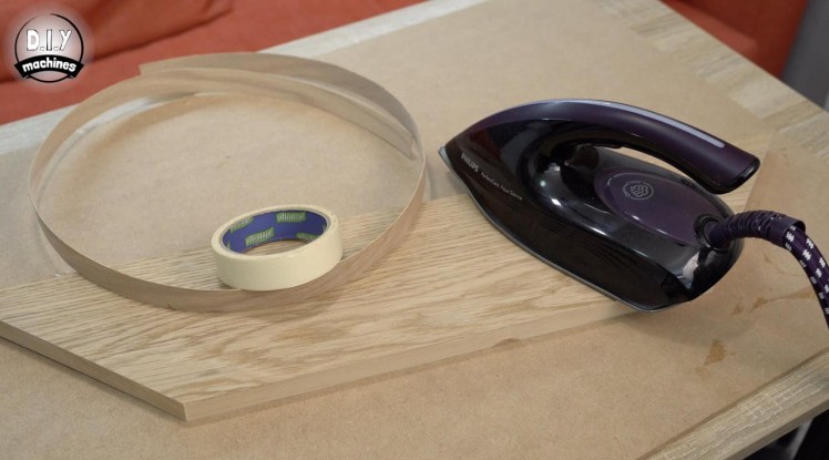
I then applied some lengths of pre-glued iron on Oak edging tape to the inside short edges of the panels using an iron on a low heat. Masking tape can be very useful to temporarily hold the tape in position as you go.
I only did the inside edges at this point as I wanted to assemble the top frame again before adding the outer edging to ensure a good finish on the exterior corners.
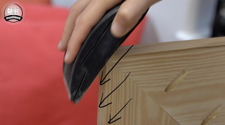
Again I then used sand paper to tidy the edges whilst being careful not to remove too much veneer or edging so as to reveal the pine below.
Step 58: Applying Exterior Edging Strips
1 / 7
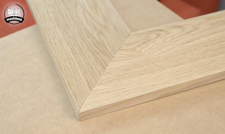
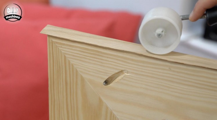
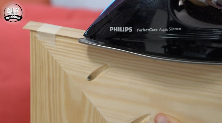
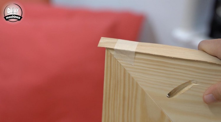
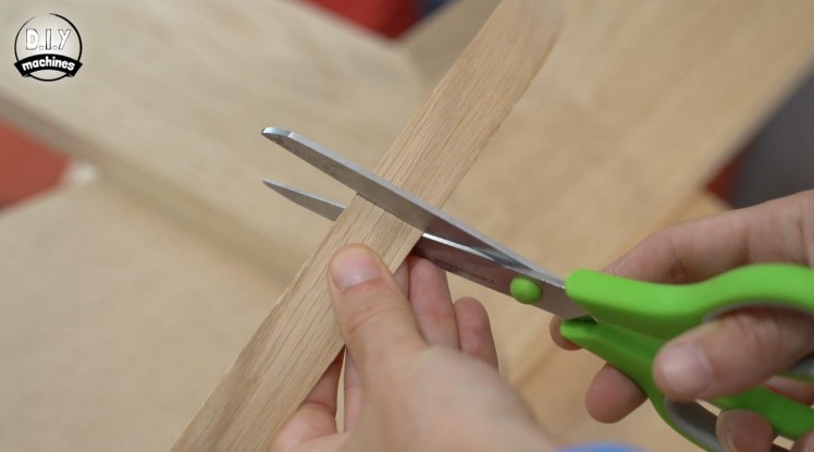
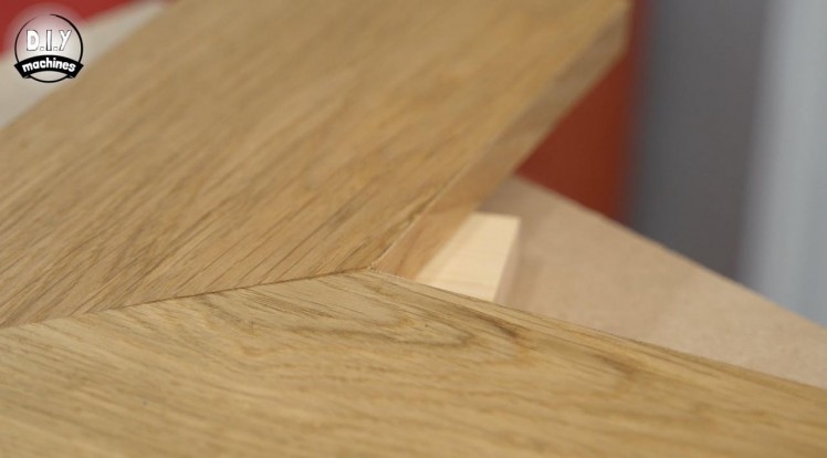
After reassembling the four sides of the frame I cut some lengths of slightly over sized edging strips.
As before, use some masking tape to hold it in position whilst you set it in place with the warmth of an iron. Complete the first two short edges first before carefully sanding the edges tidy.
We can then apply the two long edges so that they overlap the cut and sanded edge of the shorter sides. Some carefully fitting and sanding will ensure that it is well joined on the external corners.
Step 59: Treating the Wood
1 / 5
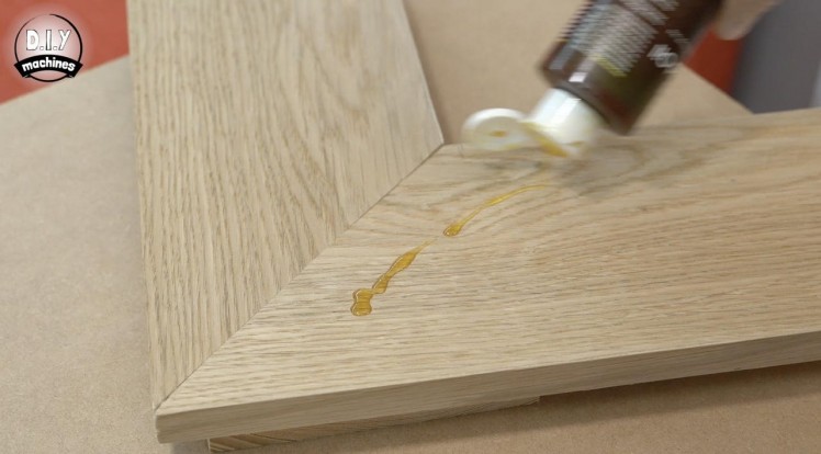
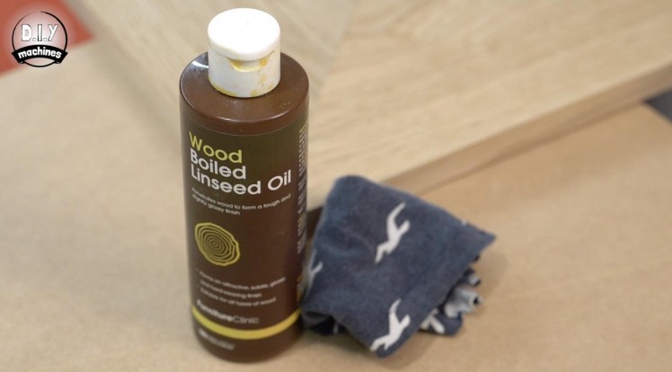
For this step you will need:
- Boiled linseed oil
- Old rags or cloth
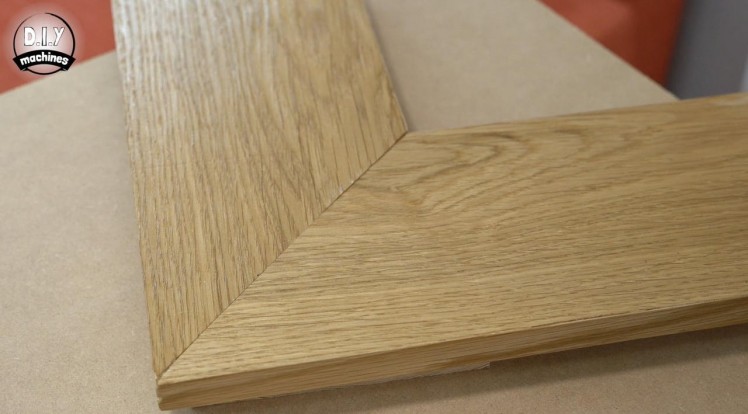
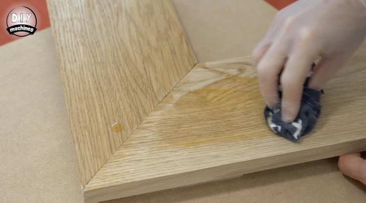
After using a hoover and slightly damp cloth to remove the dust from sanding I used some old rags to generously apply some boiled linseed oil to the edging and veneered surfaces. I left this for about 25 mins to soak in and then removed the excess.
24 hours later I repeated this process. It may not fully dry for 48 hours after the second coat so ensure that you are careful with coming into contact with the surface while it fully dries.
If you have used boiled linseed oil you will need to careful as your cloth used for oiling may spontaneously combust. It should be cleaned in warm soapy water to remove any excess oil and placed in an outside bin.
Step 60: Adding Some Glass
1 / 2
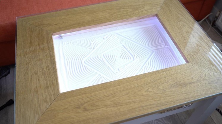
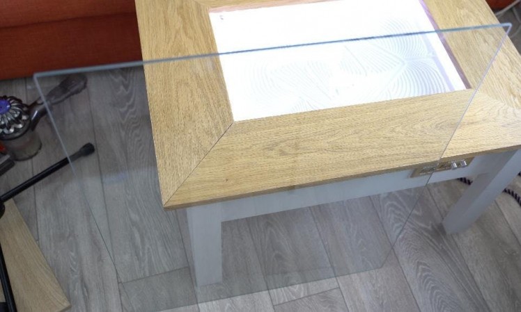
I then ordered some glass cut to size from a local supplier which simply sits on top allowing us to clearly see the art underneath whilst it can be safely used as a coffee table. As this glass is heavy it stays in place just fine.
That’s the table completed, all that’s left to do now is to show you how to easily create your own patterns and how to queue up a playlist.
Step 61: Creating Your Own Patterns
1 / 4
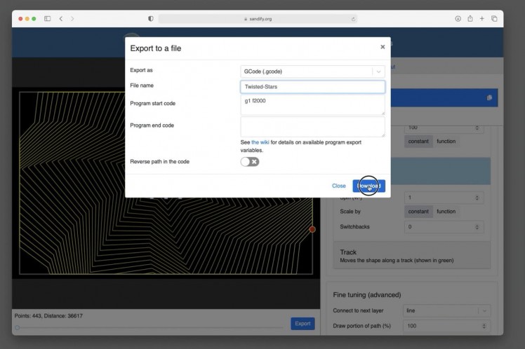
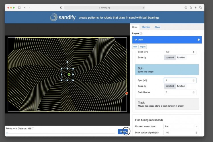
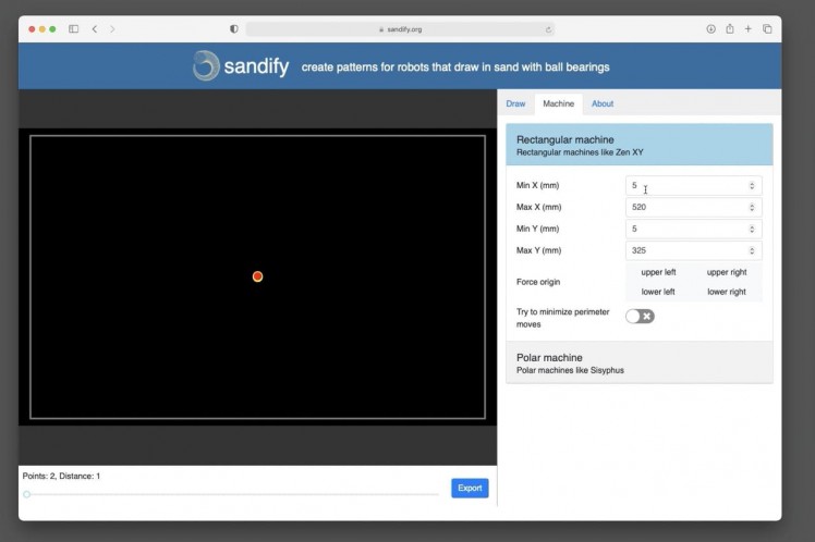
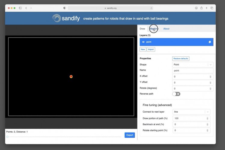
To create your own patterns head over the www.sandify.org
This is a fantastic community site created to help easily make patterns for your (and other) sand tables. Before you start adjusting the various parameters to create your pattern we should change some details so that it knows more about the machine it will be drawn on.
Open the 'Machine' tab and set the value for Min X to 5mm, Max X to 520. Min Y to 5mm and Max Y to 325mm.
You can then return to the 'Draw' window to create your own patterns. Adjust the various setting until you have created something you like and then press ‘Export’ at the bottom of the window.
Create a descriptive filename for your art and then in the ‘Program Start Code’ box enter ‘G1 F2000’.
The file you downloaded can then be uploaded to your sand table in the same manner we did with the first drawing. We can also upload the eraser.gcode file included in the projects downloads. This is a back and fourth pattern I designed to tidy up the drawing surface occasionally.
Step 62: Setting Up a Playlist
1 / 5
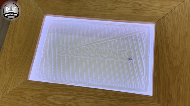
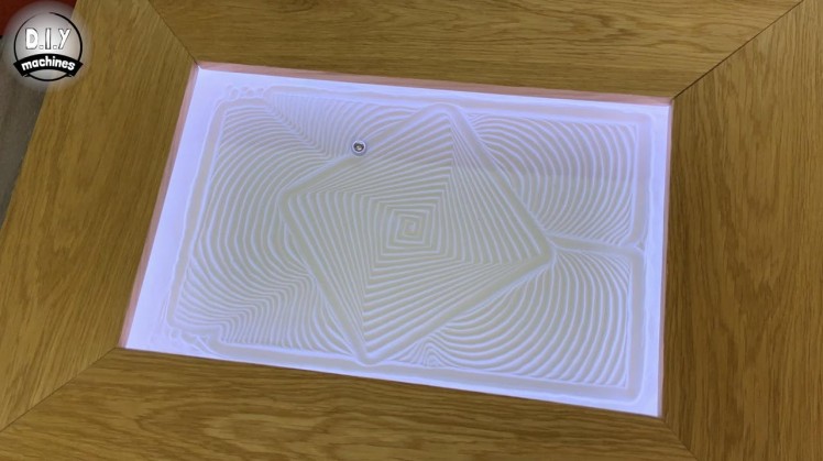
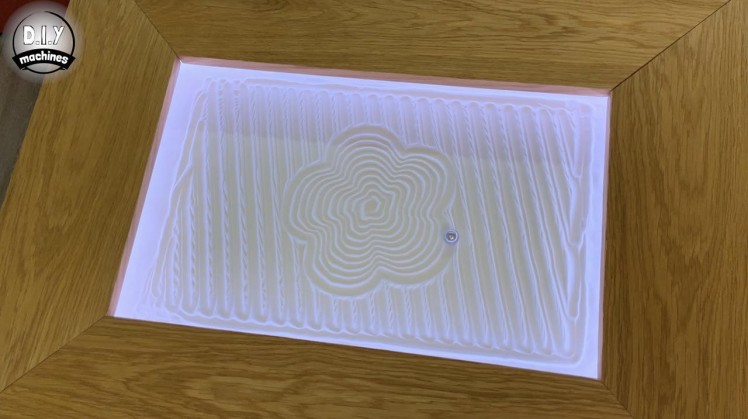
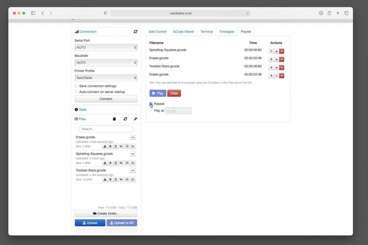
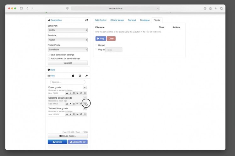
To create a playlist of patterns that flow from one to the next automatically open the 'Playlist' window in OctoPrint and then press the ‘Add to playlist’ button next to each pattern you would like to add. You can queue up several, and can include your favourites more than once.
Queuing up a pattern which covers the whole drawing area and following it up with a partial pattern can create a great effect. Using the wiper pattern every so often helps to keep the drawings canvas clean of 'clutter'.
Check the repeat box and then press play.
Step 63: Project Complete!
1 / 4
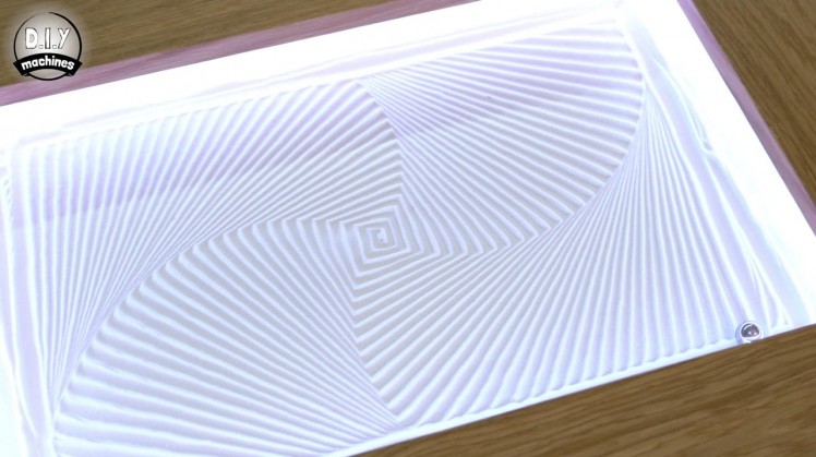
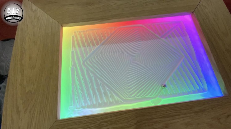
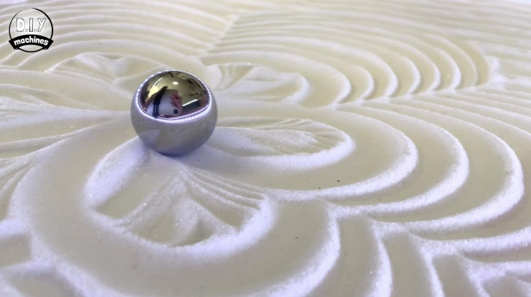
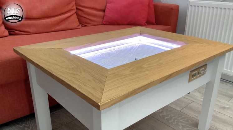
And that's the project completed! It's probably been the longest guides I've written out to date, but I have tried hard to ensure not to miss a single detail so you have every bit of information you need to successfully build one of your own. I'm really enjoying mine and the kind comments from those who have seen it 'face-to-face'.
I would love it if you wanted to support my projects, please consider subscribing to me on here and Youtube (https://www.youtube.com/diymachines). I also have a Patreon page where some very kind people are helping me to cover the cost of designing, documenting and sharing these projects. Please consider joining them in any way if you can.
Thanks for reading to the end, have a wonderful day and until next time. Ciao for now.Lewis. DIY Machines.


Leave your feedback...