
Blinksnap: Eye-controlled Raspberry Pi Camera 😉📸
About the project
BlinkSnap is an innovative project that uses Electrooculography (EOG) signals to control a Raspberry Pi camera and capture images.
Project info
Difficulty: Moderate
Platforms: Raspberry Pi, STMicroelectronics
Estimated time: 1 hour
License: MIT license (MIT)
Items used in this project
Hardware components
Software apps and online services
Story
BlinkSnap is an innovative project that uses Electrooculography (EOG) signals to control a Raspberry Pi camera and capture images. The project aims to provide an interactive and user-friendly way for individuals with disabilities to take photos using just eye blinks.
👁️ Introduction:In the world of advanced technology, we are always striving to find innovative solutions to improve the quality of life. **BlinkSnap** is a project that combines medical technology with modern computing techniques to enable individuals to capture photos using eye blinks. By using a Raspberry Pi and a connected camera, users can easily control the camera and take pictures through EOG signals. This project is not only a fun tool but also a step towards empowering individuals with disabilities to interact with technology in new and creative ways.

Electrooculography (EOG) Is a technique for measuring the corneo-retinal standing potential that exists between the front and the back of the human eye. The resulting signal is called EOG.
To measure eye movement, pairs of electrodes are typically placed either above and below the eye or to the left and right of the eye. If the eye moves from center position toward one of the two electrodes, this electrode "sees" the positive side of the retina and the opposite electrode "sees" the negative side of the retina. Consequently, a potential difference occurs between the electrodes. Assuming that the resting potential is constant, the recorded potential is a measure of the eye's position.
In 1951 Elwin Marg described and named electrooculogram for a technique of measuring the resting potential of the retina in the human eye.
Common electrode placement for vertical and horizontal EOG recording 👀
- Right and left eye movement: horizontal electrodes.
- Up and down eye movement: vertical electrodes.
- The common electrode you can place it on the forehead or neck.
Up and down eye movement
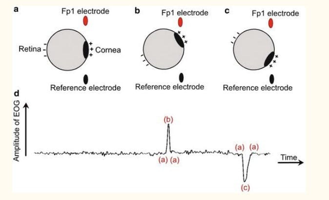
Up and down eye movement
🌟 Single-Lead, EXG Monitor (H2BR0x):
Hexabitz Single-Lead, EXG Monitor Module (H2BR0) is one of a kind module that can record publication-grade biopotential signals from your body be it from the heart (ECG), brain (EEG), eyes (EOG), and muscles (EMG).
What makes it different?
- Record publication-quality biopotential signals like ECG, EMG, EOG, or EEG.
- Small size allows easy integration into mobile and space-constrained projects.
- Notch filter (second order) to remove 50 Hz AC mains.
- H2BR0 is based on STM32G0 MCU.
- Program advanced C code with our easy-to-use APIs.
- You can connect to external hardware or combine with other Hexabitz modules!
- The module is equipped with an open source MATLAB interface.
1 / 2 • H2BR0
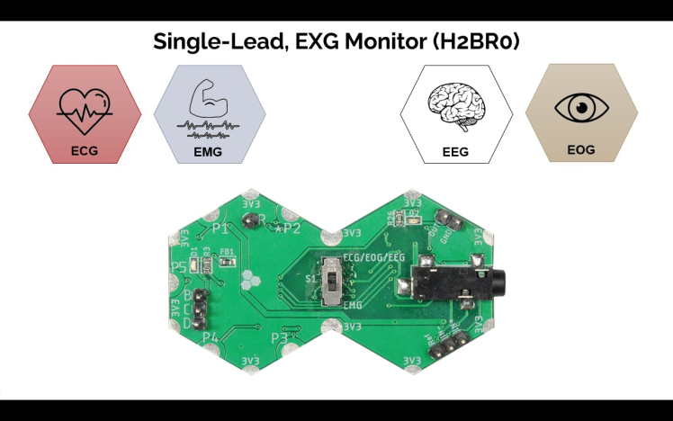
H2BR0
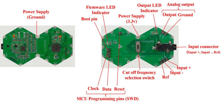
- Collecting EOG Signal Samples: Using the Hexabitz module to gather EOG signal samples from the eye.
- Transmitting Samples: Sending the collected values via Raspberry Pi interface module to the Raspberry Pi.
- Processing Signals: Analyzing the EOG signals with Python code.
- Activating the Camera: Triggering the Raspberry Pi camera to capture images upon detecting specific EOG signals.
- Connection: The Hexabitz module is connected to the Raspberry Pi via serial communication.
- Data Collection: The Hexabitz module continuously collects EOG signal samples from the eyes.
- Data Transmission: The collected values are sent to the Raspberry Pi for examination.
- Data Analysis: Python code is used to analyze the signals and determine the appropriate moment to activate the camera.
- Image Capture: When a specific eye signal (such as a blink) is detected, a command is sent to activate the camera and capture the image.

Step 1 :🖥️ Hexabitz Module Setup:
- Check out this article for writing code with STM32CubeIDE.
The ExG module main code:
This code is designed for interfaces with an EOG sensor, reading EOG signals and transmitting them to a Raspberry Pi via serial communication ( It initializes the sensor, reads samples, and sends them to port P4) 😊
- The `UserTask` function is the main user-defined task.
- It initializes the EOG (Electromyography) sensor using `EXG_Init(EOG)`.
- Inside the infinite loop, transmit a sample via the designated port or route it to another module and scale the output accordingly.
- In case the topology file remains inactive, the module number defaults to 0
SampletoPort(0,P4,EOG);Step 2 : 🖥️ Raspberry Pi Setup:
- Connect the ExG module to HF1R0 module.
1 / 2
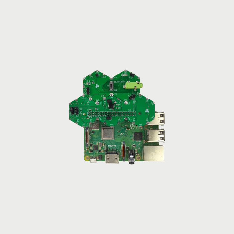
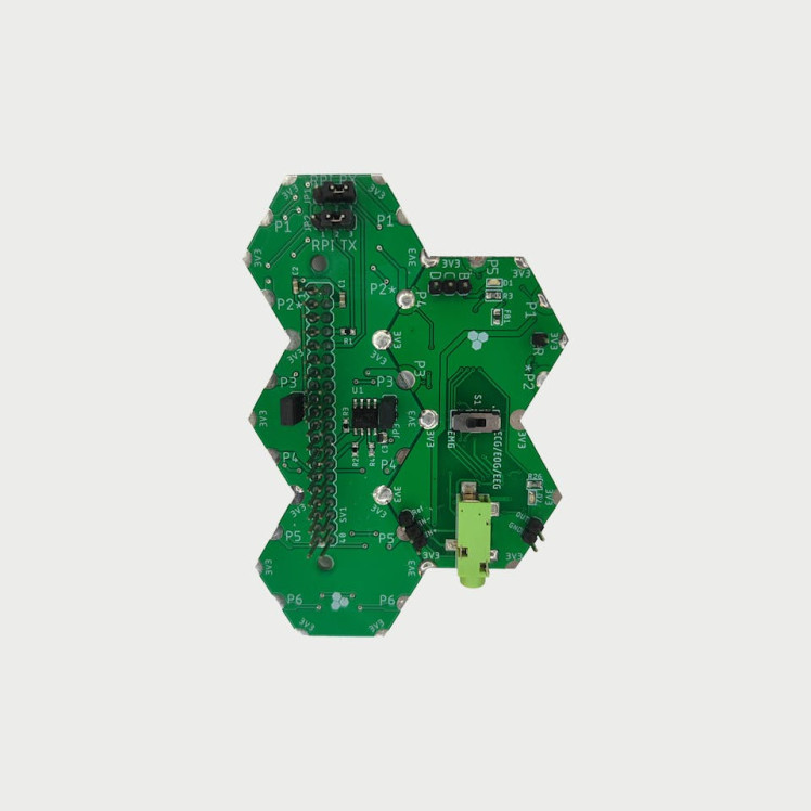
- Make sure to connect your Hexabitz module at the wright spot or left spot then put the HF1R0 Jumper JP1 and JP2 at right position.
- Be sure to download the firmware on the module before soldering.

Python Code Implementation: 🧐
This code is designed to read eye signals from a Hexabitz module via a serial connection, check if the signals exceed a certain threshold, and capture an image using the Raspberry Pi camera if the threshold is exceeded. The code is structured using an object-oriented approach for better modularity and readability.
Python Code Flow Chart

Python Code Flow Chart
This project involves creating a system that uses EOG signals from the eyes to control a Raspberry Pi camera for capturing images. The system detects eye movements (such as blinks) and uses these signals to trigger the camera. The code is divided into several key components:
Importing Necessary Libraries
The code begins by importing several libraries that are essential for its operation:
import serial
import struct
import logging
import time
import os
import numpy as np
Setting Up the Serial Connection
The serial connection to the Hexabitz module is established with the following settings:
ser = serial.Serial(
port='/dev/ttyS0',
baudrate=921600,
parity=serial.PARITY_NONE,
stopbits=serial.STOPBITS_ONE,
bytesize=serial.EIGHTBITS,
timeout=0
)
port: The serial port used for communication.
baudrate: The speed of the communication (921600 baud).
parity, stopbits, bytesize: Configuration for serial communication.
timeout: Timeout for reading from the serial port.
Setting Up Logging
Logging is configured to capture information, warnings, and errors:
logging.basicConfig(level=logging.INFO, format='%(asctime)s - %(levelname)s - %(message)s')level: The logging level is set to INFO to capture informational messages and above.
format: The format of the log messages, including the timestamp, logging level, and the message.
EyeSignalProcessor Class
This class handles reading eye signals, processing them, and capturing images based on the signals.
This class encapsulates the functionality to process eye signals:
class EyeSignalProcessor:
def __init__(self, samples_count=100, threshold=2.3, capture_interval=5):
"""Initialize the processor with sample count, threshold, and capture interval."""
self.samples_count = samples_count
self.threshold = threshold
self.capture_interval = capture_interval
self.last_capture_time = 0- This class handles reading eye signals, processing them, and capturing images based on the signals.
- Initialization (`__init__` method):
- Initializes the processor with the number of samples (`samples_count`), a threshold value for detecting eye blinks, and a capture interval to control how often images are captured.
- Reading Eye Signals (`read_eye_signals` method):
- Reads eye signals from the serial port. It reads a specified number of samples, each consisting of 4 bytes, and logs the sensor values.
ser.read(4): Reads 4 bytes of data from the serial port.
struct.unpack('f', x): Converts the byte data to a float value.
- Check and Capture (`check_and_capture` method):
- Checks if any signal exceeds the threshold. If it does and the capture interval has passed, it captures an image.
- Capture Image (`capture_image` method):
- Captures an image using the Raspberry Pi camera and applies visual effects to the image. It also triggers a flash effect to indicate image capture.
- Apply Effects (`apply_effects` method):
- Opens the captured image and applies a Gaussian blur filter and color enhancement to the image. The enhanced image is saved with a new name.
- Show Flash (`show_flash` method):
- Uses tkinterto create a flash effect on the screen, indicating that an image has been captured. This is done in a separate thread to avoid blocking the main program.
Main Program Loop
- The `main` function initializes the `EyeSignalProcessor` and continuously reads eye signals, checks for threshold exceedance, and captures images if necessary. A short delay is added between iterations to prevent excessive resource consumption.
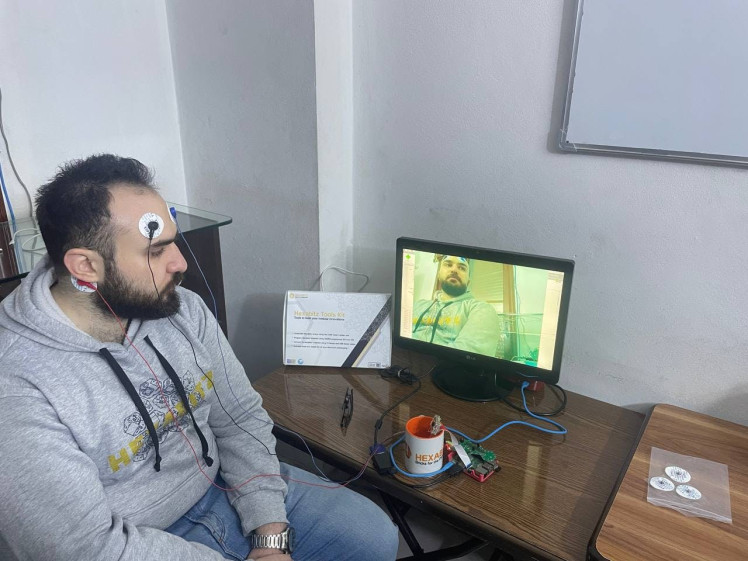
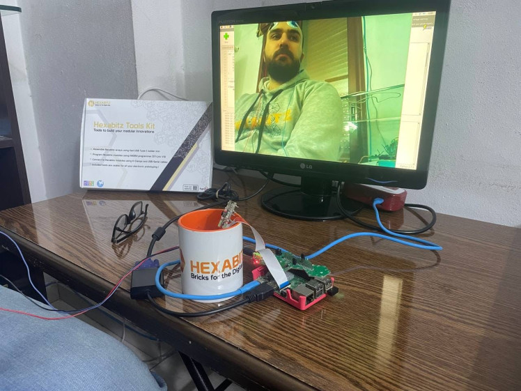
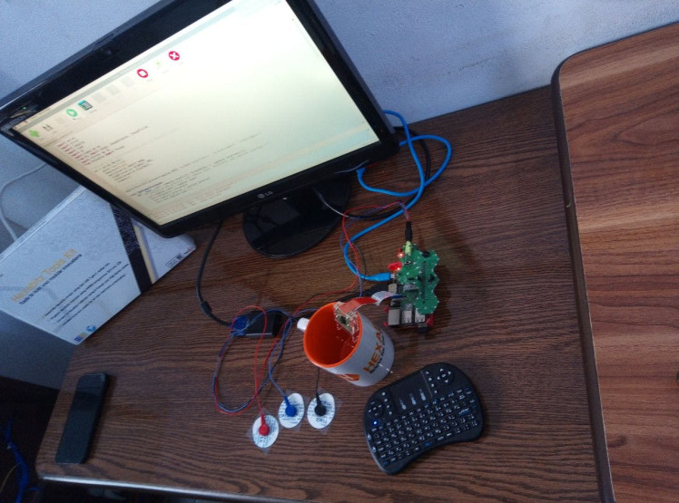
✨ Project TestingThe BlinkSnap system was tested to ensure its accuracy and reliability in detecting eye blinks and capturing images. The testing process involved several steps:
1. Signal Detection:
The system was first tested to accurately detect EOG signals corresponding to eye blinks. This was done by having users blink at specific intervals while monitoring the signals to ensure they were correctly identified and recorded.
2. Image Capture:
Once the signal detection was confirmed, the system's ability to capture images was tested. This involved triggering the camera based on detected blinks and verifying that images were captured promptly and clearly.
3. Environmental Conditions:
The system was tested under different lighting conditions and backgrounds to ensure it could function effectively in various settings. This included testing in both dim and well-lit environments to confirm the camera's performance.
4. Usability:
Feedback from users was collected to assess the system's usability and comfort.
1 / 2
1 / 7
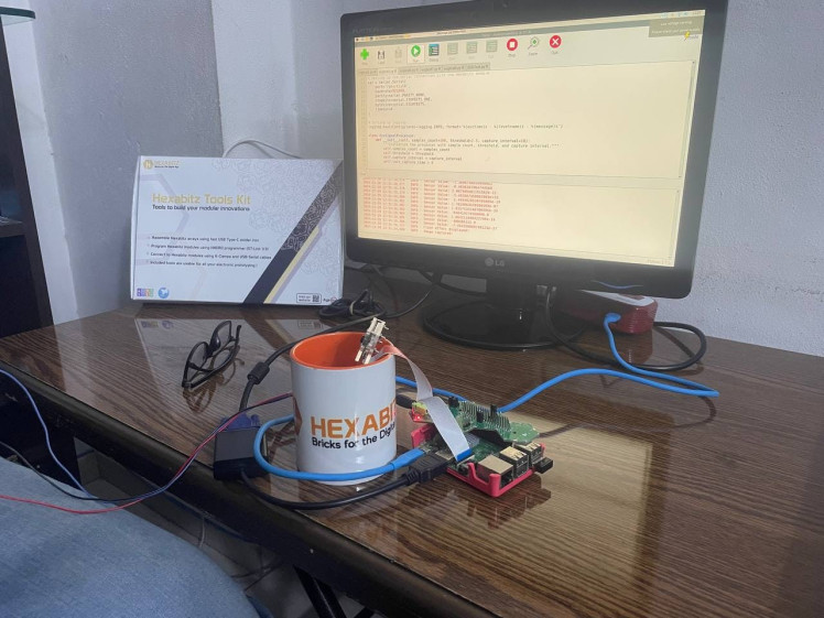
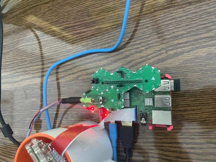
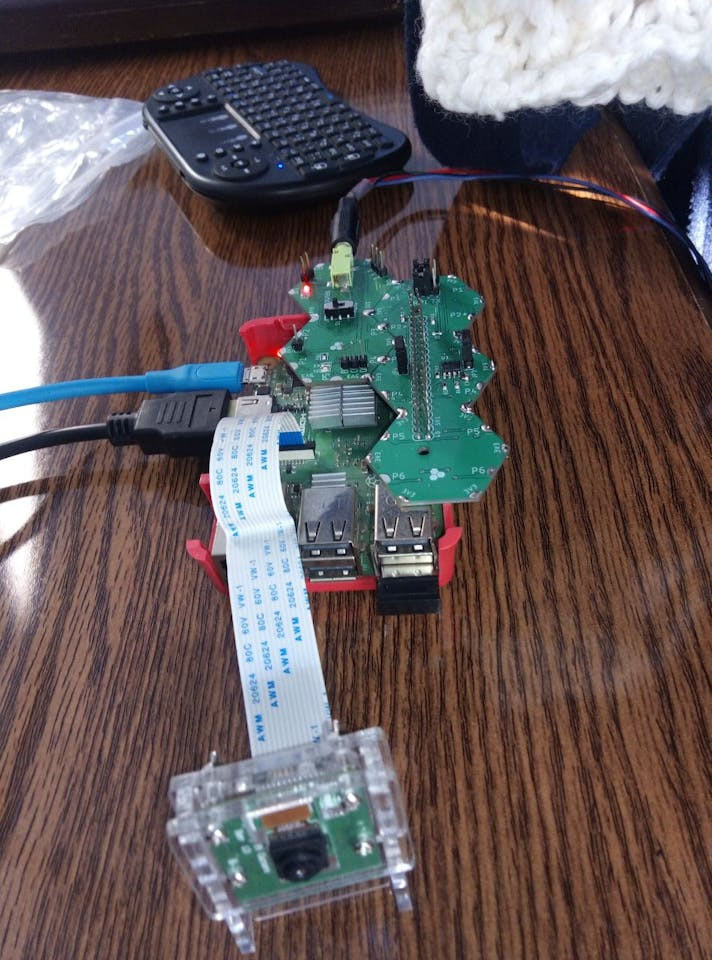
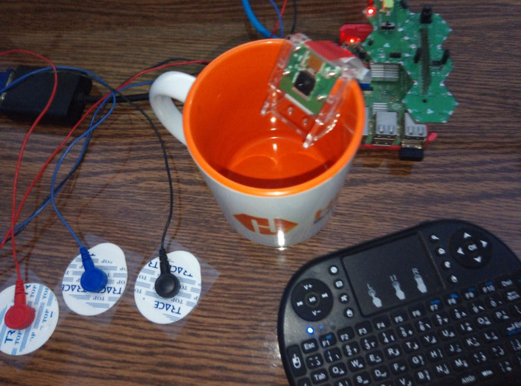
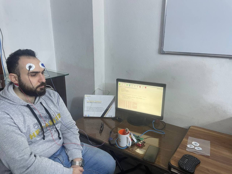
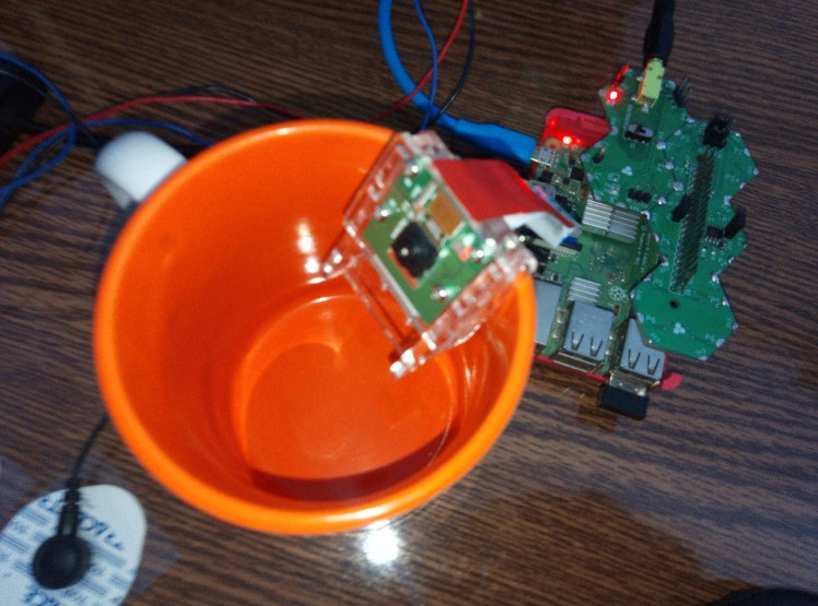
The BlinkSnap project, which uses EOG signals from the eyes to control a Raspberry Pi camera, presents numerous exciting possibilities for future developments. One potential area for advancement is enhancing the sensitivity and accuracy of signal detection, enabling the system to recognize more subtle eye movements and different gestures. This could expand the system's applications, making it more versatile for users with different needs.
Additionally, integrating the BlinkSnap system with other smart home devices could offer new automation opportunities. For instance, it could be used to control lights, appliances, and other home systems through eye movements. This would be particularly beneficial for individuals with limited mobility, providing them with a more convenient and accessible way to interact with their environment.
Another promising application is in the field of assistive technology. BlinkSnap could be adapted to serve as a communication aid for people with severe disabilities, allowing them to take photos, send messages, or control devices using only their eyes. Moreover, the system could be refined for use in medical settings, where monitoring eye movements could assist in diagnosing and managing neurological conditions.


