


Project info
Difficulty: Easy
Platforms: Microchip
Estimated time: 1 hour
License: GNU General Public License, version 3 or later (GPL3+)
Items used in this project
Hardware components

View all
Story
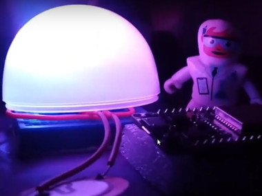
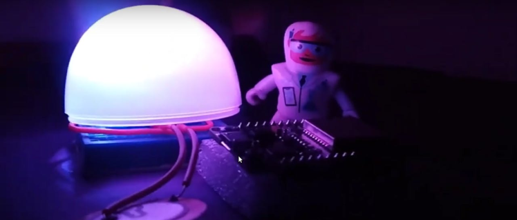
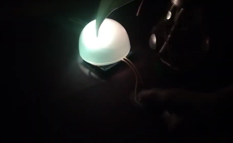
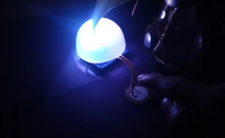
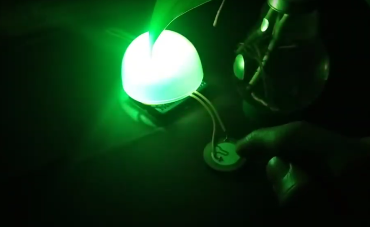
The RGB Dome is a mood lamp powered by the ATtiny85 microcontroller. This compact lamp features cool light effects by altering the power on each RGB channel (red, green, and blue) to create various color mixes. By using pulse width modulation (PWM), we can control the brightness of each color and produce the desired hue. While this sounds straightforward, the small size of the ATtiny85 introduces unique challenges and solutions.
The ATtiny85 has only two PWM-supported pins. When I initially uploaded the code, it worked, but the colors flickered constantly, which was unsatisfactory. The solution was to implement software PWMâ€â€a technique for generating PWM output signals without needing a dedicated PWM hardware module within the microcontroller.
After researching, I found that software PWM could be implemented on the ATtiny85, allowing for smooth color mixing and gradient changes. The result was beautiful, but I wanted to add more features, such as changing to a specific color upon receiving an input or functioning as an RGB mood lamp. A piezo sensor seemed like a handy addition to enable color changes by clapping.
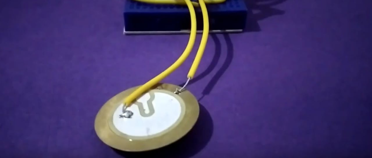
Initially, the piezo sensor didn't work as expected. The colors wouldn't change due to a small bug in the code. After debugging and making necessary adjustments, the sensor functioned correctly.
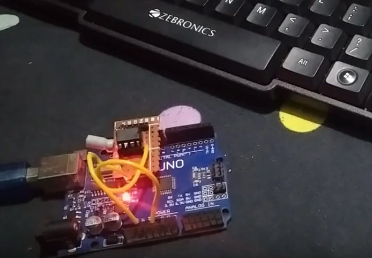
Programming the ATtiny85I used an Arduino as an ISP programmer to upload the code to the ATtiny85. If you're unfamiliar with this process, check out this
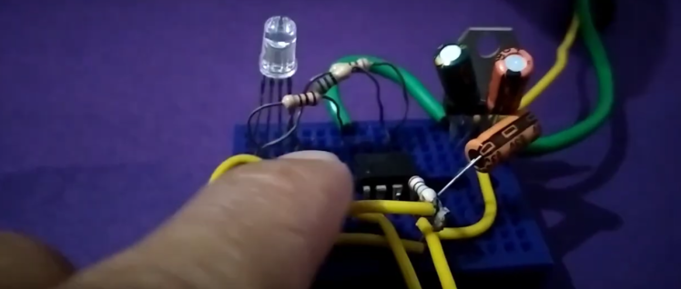
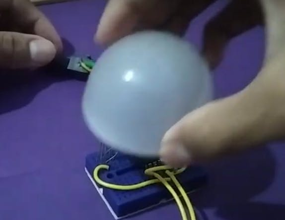
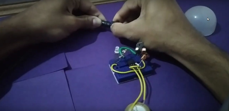
for guidance. Once programmed, place the ATtiny85 back into the circuit, connect a 12-volt adapter, and enjoy your RGB Dome lamp. The connections are made as shown in the schematic. The diffuser I am using here is from an old bulb.
1 / 2
A DC 12V adapter is connected to a female DC power jack. The input passes through a voltage regulator and some decoupling capacitors to ensure a stable operating voltage between 1.8V and 5.5V for the ATtiny85.
The RGB Dome mood lamp project showcases the versatility of the ATtiny85 microcontroller despite its limitations. By implementing software PWM and adding a piezo sensor for interactive color changes, you can create a small yet functional and visually pleasing mood lamp. Enjoy the vibrant colors and smooth gradients of your custom RGB Dome lamp!

Code
Credits
Related products


Leave your feedback...