


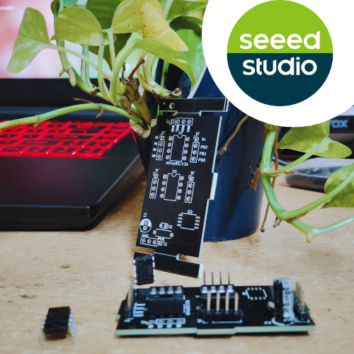
Attiny85/13a Programming Shield For Arduino

Made by vin-vout-io
About the project
No more messy wires! Looking for an easy way to program ATtiny85 & ATtiny13A microcontroller
Project info
Difficulty: Moderate
Platforms: Arduino, Microchip, Seeed Studio
Estimated time: 1 hour
License: GNU General Public License, version 3 or later (GPL3+)
Items used in this project
Hardware components
Story
Hey makers! If you’ve ever worked with ATtiny85 or ATtiny13A microcontrollers, you know that programming them can be a hassle—especially with messy jumper wires.
In this post, I’ll introduce my custom ATtiny85/13A programming shield for Arduino Uno, which simplifies the process and makes programming effortless

Story
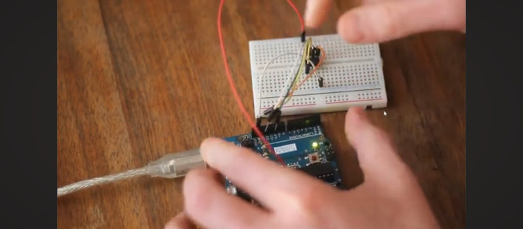
I am a big fan of these microcontrollers, but I was fed up with the wiring I have to do every single time when I had to program them, so initially, I built this programmer on a perfboard,
1 / 2
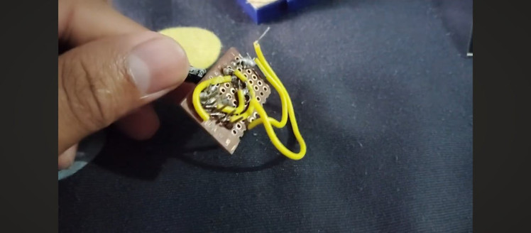

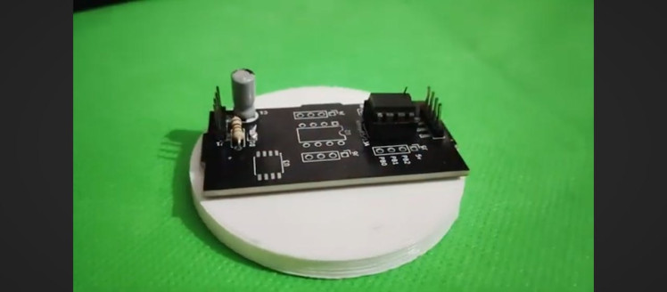
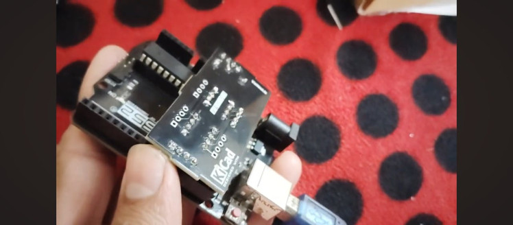
but I later upgraded it to a professional PCB design with improved functionality. This shield eliminates the need for a tangle of wires and ensures reliable programming every time. Whether you’re working on mini projects or low-power applications, this tool will make your development process much easier.
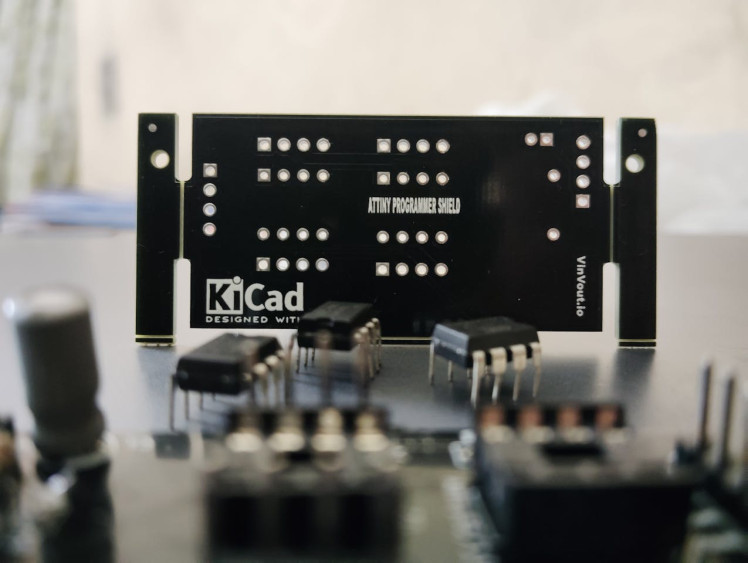
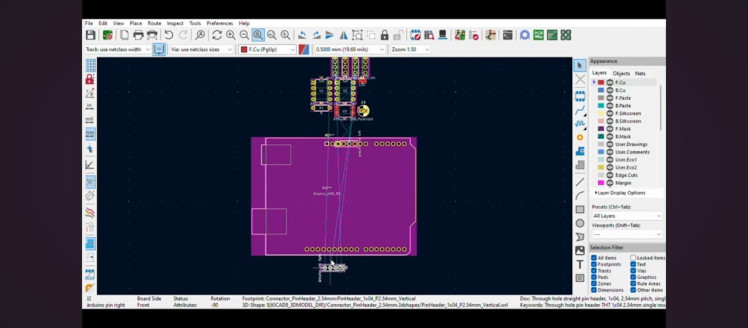
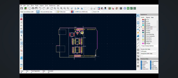
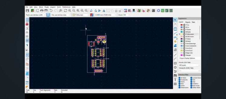
For designing this shield, I used KiCad. To ensure that the header pins of the shield aligned perfectly with the Arduino Uno’s pins, I followed these steps:
- Importing the Arduino Uno Footprint – In the PCB editor, I imported the Arduino Uno footprint as a reference.
- Aligning the Headers – Using KiCad’s align tool, I precisely aligned the shield’s headers with those of the Arduino Uno.
- Finalizing the Design – Once the alignment was perfect, I deleted the Arduino footprint and completed the rest of the sketch.
This process ensured that the shield fit seamlessly onto the Arduino Uno, avoiding any misalignment issues during assembly
1 / 3

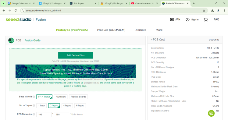
This project was brought to life with the help of Seeed Studio Fusion, a global one-stop online platform for PCB manufacturing, assembly, and hardware customization. I uploaded my Gerber files to Seeed Studio Fusion and had my professionally manufactured PCBs delivered seamlessly.
 Whether you need prototyping, mass production, custom solutions for open-source products,

or transformation of your creative ideas into profitable products, Seed Studio Fusion can meet your requirements.
Design and Features
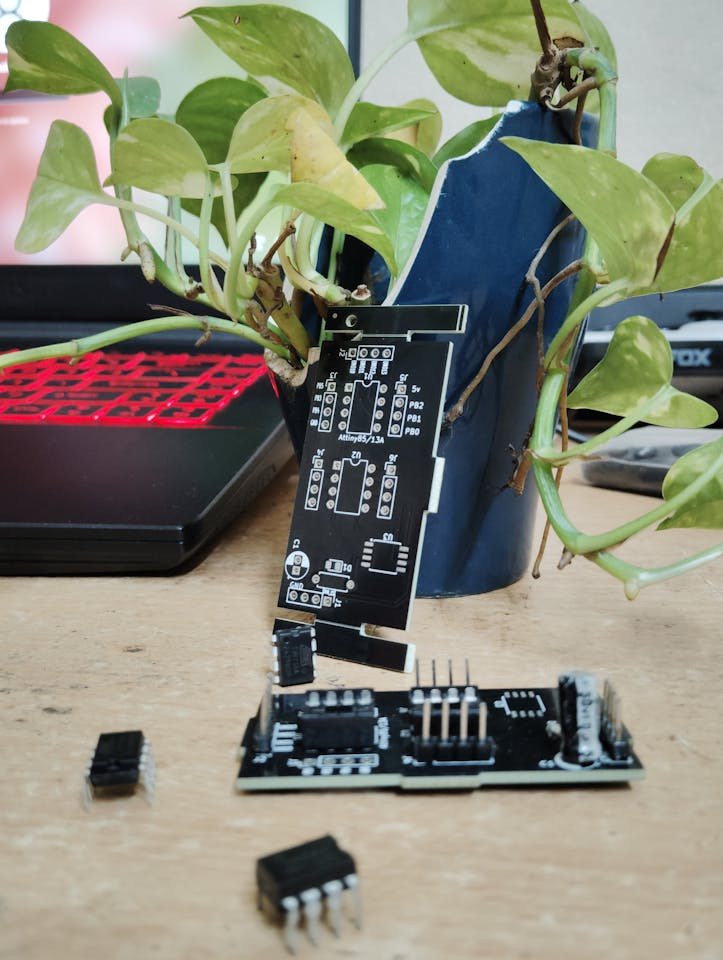
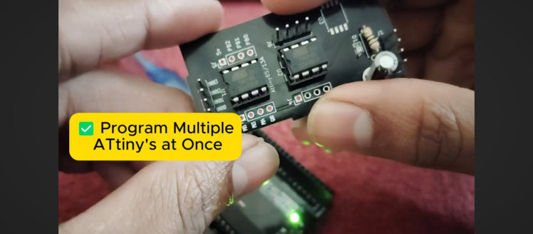
One interesting design quirk: I initially made an error where the components were placed upside down when plugged into the Arduino Uno. Surprisingly, this turned out to be a good thing—it prevents accidental damage to the Arduino GPIO pins. However, there is a minor fitting issue when programming two ATtiny chips at the same time. Despite this, the shield functions without any major problems.
1 / 2
- Dual Programming – Program two ATtiny chips simultaneously, saving time when flashing multiple chips.
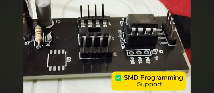
- SMD Support – Space included for programming surface-mount ATtiny versions.
- Onboard LED – Connected to GPIO4 for quick testing without external components.

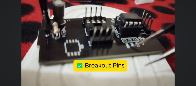
- Breakout Pins – Useful for prototyping and debugging.
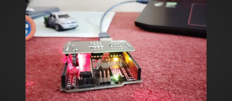
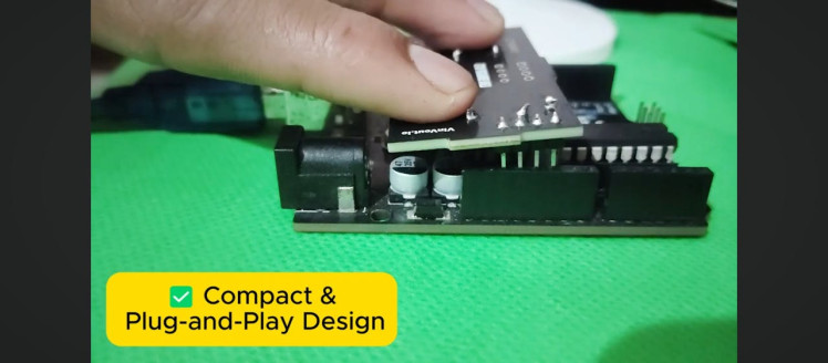
- Compact Plug-and-Play Design – No need for jumper wires—just mount and program.
Using this shield is straightforward:
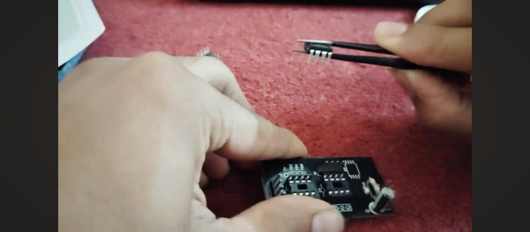
- Insert the ATtiny85 or ATtiny13A into the IC base.
- Mount the shield onto the Arduino Uno.
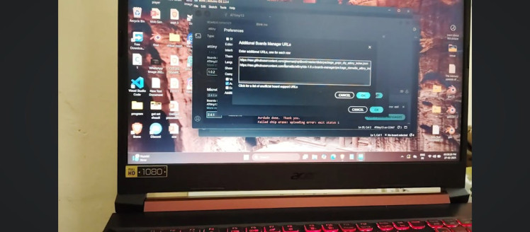
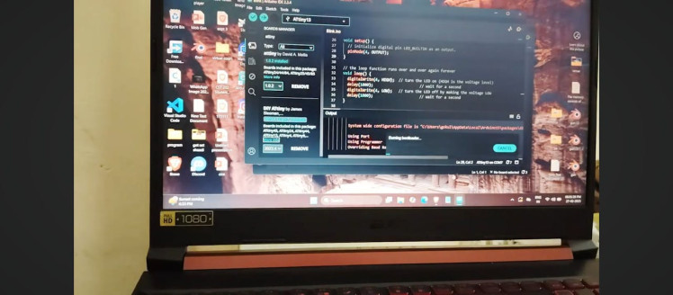
- In the Arduino IDE, install the ATtiny board support package from the Boards Manager.
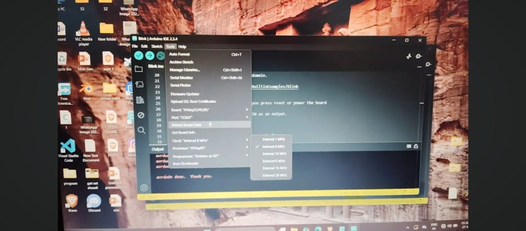
- Select the correct board and clock settings.
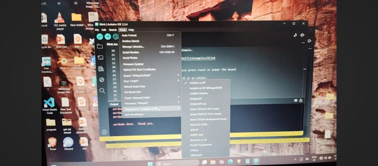
- Set the programmer to Arduino as ISP.
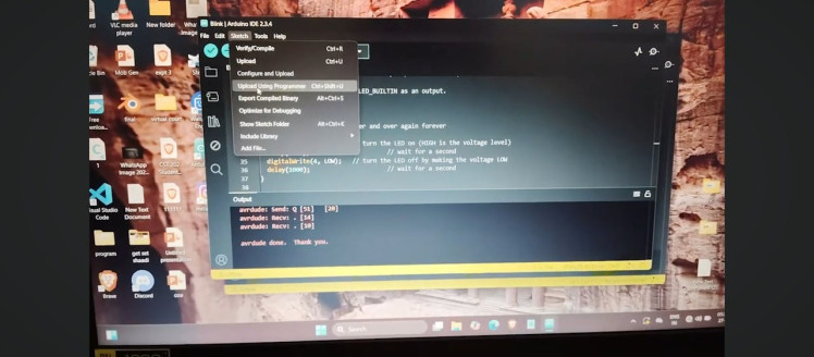
- Upload the Arduino ISP sketch to the Arduino Uno.
- Choose the COM port and upload using the programmer.
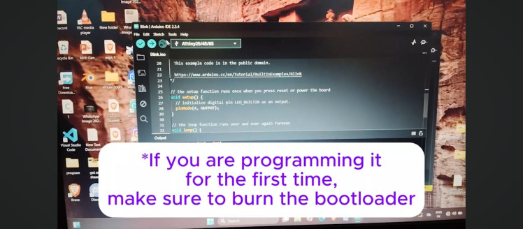
(Note: If you are programming it for the first time, make sure to burn the bootloader)
1 / 8

For detailed instruction on programming:
ATTINY85:
ATTINY13A:
That’s it! Your ATtiny85 or ATtiny13A is now programmed and ready to go.
Troubleshooting ATtiny85 Programming IssuesDuring testing, I noticed that sometimes the ATtiny85 doesn’t program correctly. However, this issue isn’t related to the shield—I encountered the same problem while connecting it by using wires and breadboard. I suspect it might be due to inconsistent 5V power from the USB port. Testing across multiple computers, I found that some laptops had trouble recognizing the programmer, while others worked fine. Interestingly, the ATtiny13A had no such issues.
Please comment below if you know the reason for this.
ConclusionWithout this shield, you’d have to manually connect six wires every time you program an ATtiny, increasing the chances of errors. This shield saves time, reduces mistakes, and makes the entire process smoother.
If you found this post helpful and want to see more content like this, consider subscribing to my YouTube channel and also follow here for more tutorials on hardware, IoT, and embedded systems.
Happy making, and see you in the next project!
Credits
Related products


g