Arduino Wedding Photo Booth - 3d Printed Parts, Simple
About the project
Automated Photo Booth for less than hiring one (if you have a DSLR). It's controlled by an Arduino Nano so you don't need anyone to 'man it' throughout the night. The guests just press the giant arcade button and the photo booth guides them through their own photoshoot sequence. :)
Items used in this project
Hand tools and fabrication machines
Story
Step 1: What You Will Need:

You will need a few things to build your own. I've put some links to the parts on Amazon below:
- An Arduino Nano(x1): https://geni.us/ArduinoNanoV3
- 2.2k and 1k resistor (x1 of each): https://geni.us/Ufa2s
- Giant illuminated arcade button: https://geni.us/GiantArcadeButton
- MAX7219 Display Matrix: https://geni.us/MAX7219DotMatrix
- A shutter release cable for your SLR camera - I've built and tested this photo booth with a Canon camera.
- Canon SLR - https://geni.us/CanonSLR
- Canon EOS/Rebel SLR https://geni.us/CanonEOSSLR
- Nikon SLR: https://geni.us/NikonSLR
- Sony SLR: https://geni.us/SonySLR
- Breadboard or some perforated board - I will show you how to connect everything together using either one.
- Breadboard: https://geni.us/BreadboardMedium
- Perfboard: https://geni.us/PCBPerfBoard
- A screen or monitor (I'm using this 23" ASUS VC239H): https://geni.us/ASUSMonitor23
- Some small lengths of hook up wire for the internal electronics: https://geni.us/22AWGWire
- Four longer lengths of wire for connecting to the arcade button (I used two lengths of speaker wire): https://geni.us/SpeakerWire
- Some filament for the 3D printed parts: https://geni.us/ElegooPLA
- And a digital SLR camera: https://geni.us/SLRCameras
For the housing
Some wooden panels Some screws Paint and other materials for decoration.
Step 2: Printing the Camera Mount
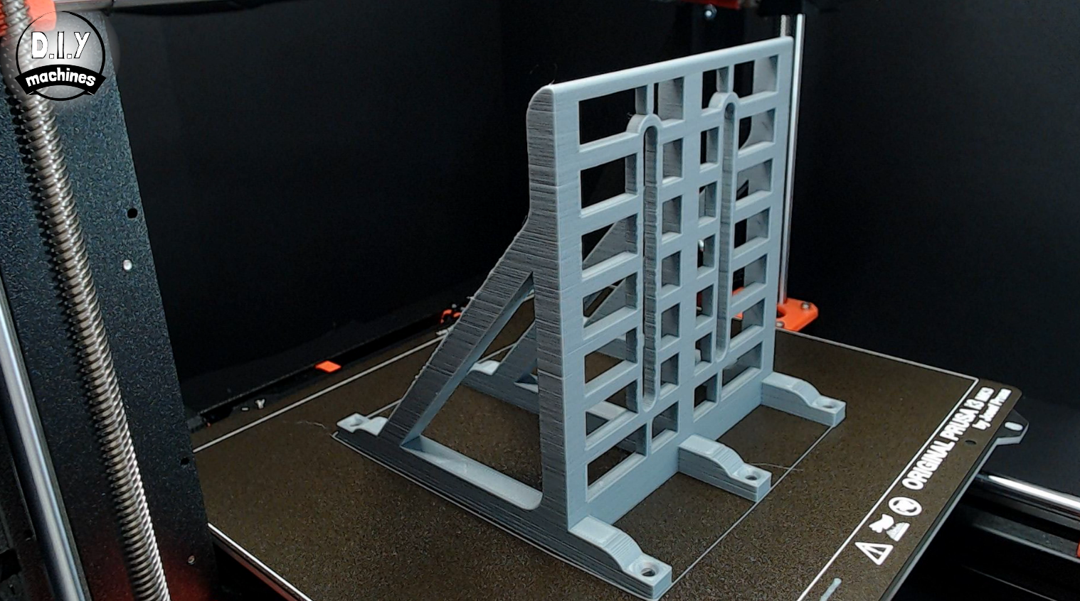
The file for the camera mount can be printed from PLA or a similar material. I printed mine at a layer height of 0.3mm and it took just under 7 hours to print. You do not require any supports and I did not need a brim on my heated print bed.
Use a high infill percentage as it has to support the weight of your camera. I chose to print mine with a 60% infill.
Step 3: Cutting Wood for the Housing
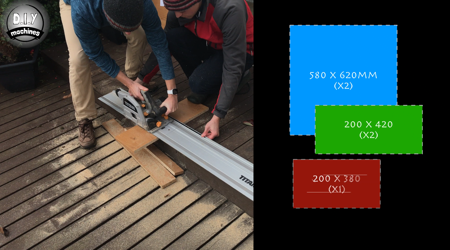
For the housing, you need to cut five different panels of wood. I cut mine from some scrap 18mm MFC I had laying around.
You need to cut the following sized panels:
- 580 x 620mm (x2)
- 200 x 420mm (x2)
- 200 x 380mm (x1)
Step 4: Cut-outs in the Front Panel
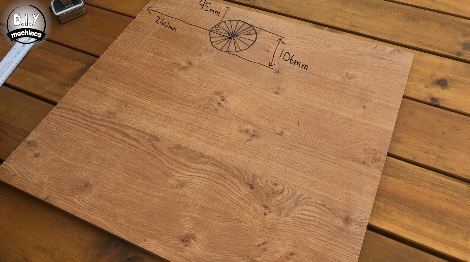
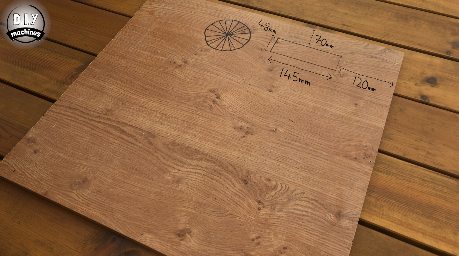
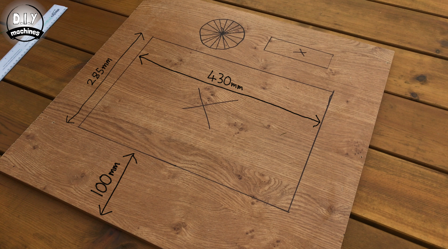
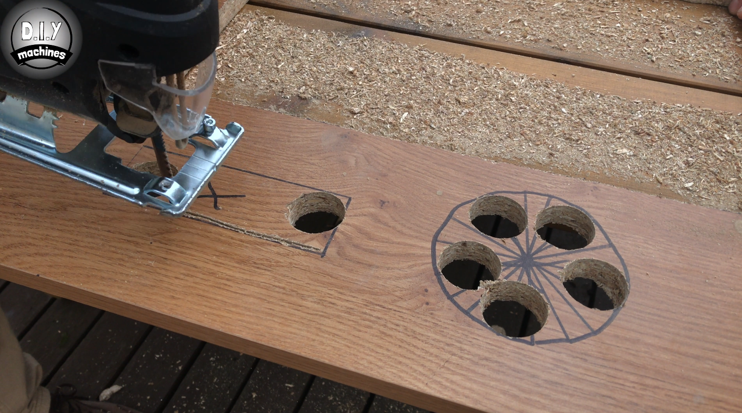
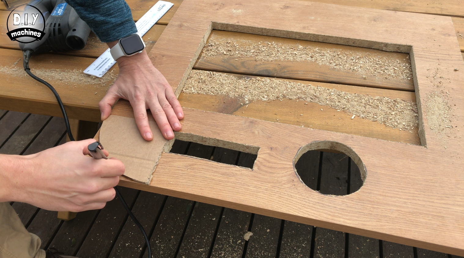
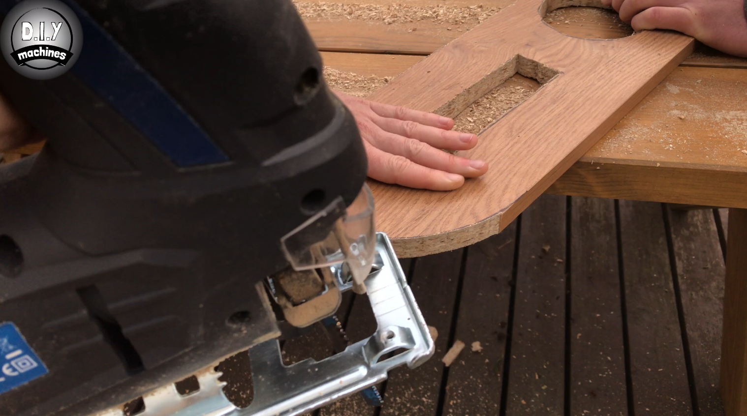
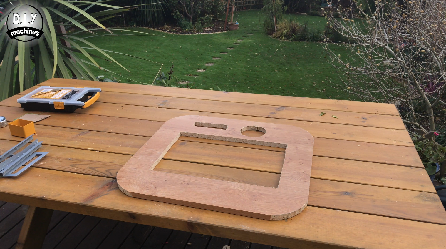
The front panel will need three cut-outs in it. These are for the LED display, camera lens, and monitor.
Lens Hole
The circular hole for the lens needs to be 106mm in diameter with its centre point about 95mm from the top and 240mm in from the side.
LED Display Hole
The rectangular cut-out for the LED display should be made about 145mm wide by 48mm tall with its short edge 120mm in from the side of the board and top edge down 70mm from the top of the board.
Monitor Hole
The cut out for the monitor (if your using the same one like me) should be made 285mm tall and 430mm wide. Centre it widthways across the board and with its bottom edge 100mm up from the outside of the board.
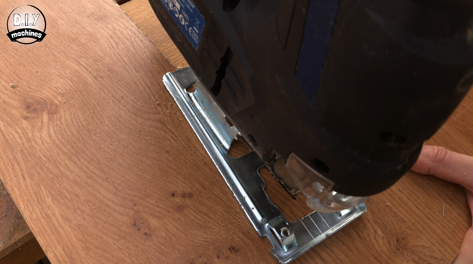
I found it easiest to mark the size of the cutouts and then drill a hole on the inside of the boundaries to then allow me to use a jigsaw to create the cutout.
Once this has been done add a 100mm radius cut to each of the corners. This should be done to all four corners of both the boards which measure 580 x 620mm.
Step 5: Assemble the Housing
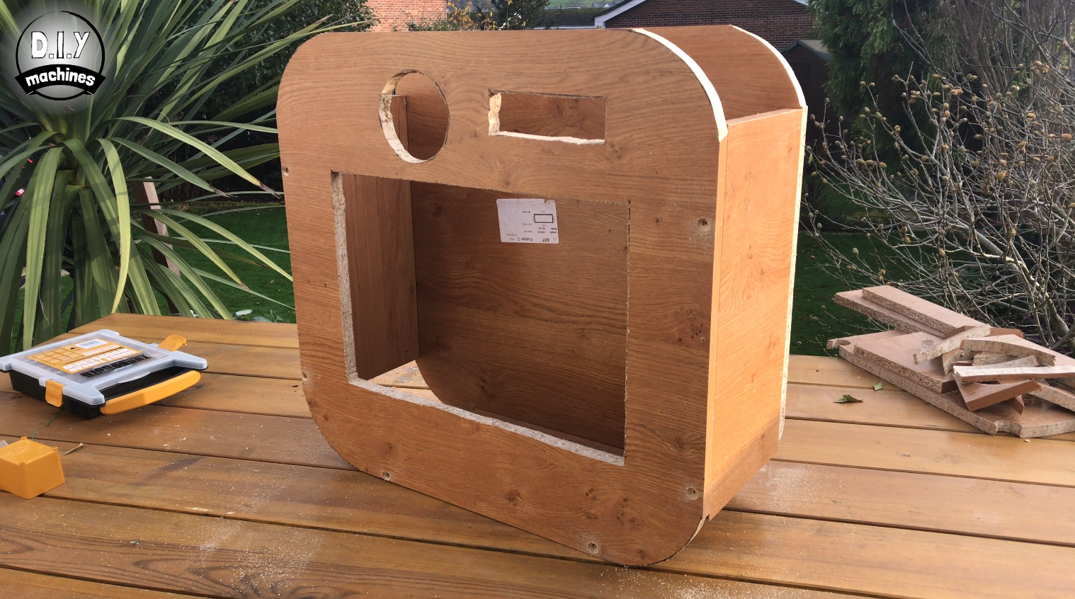
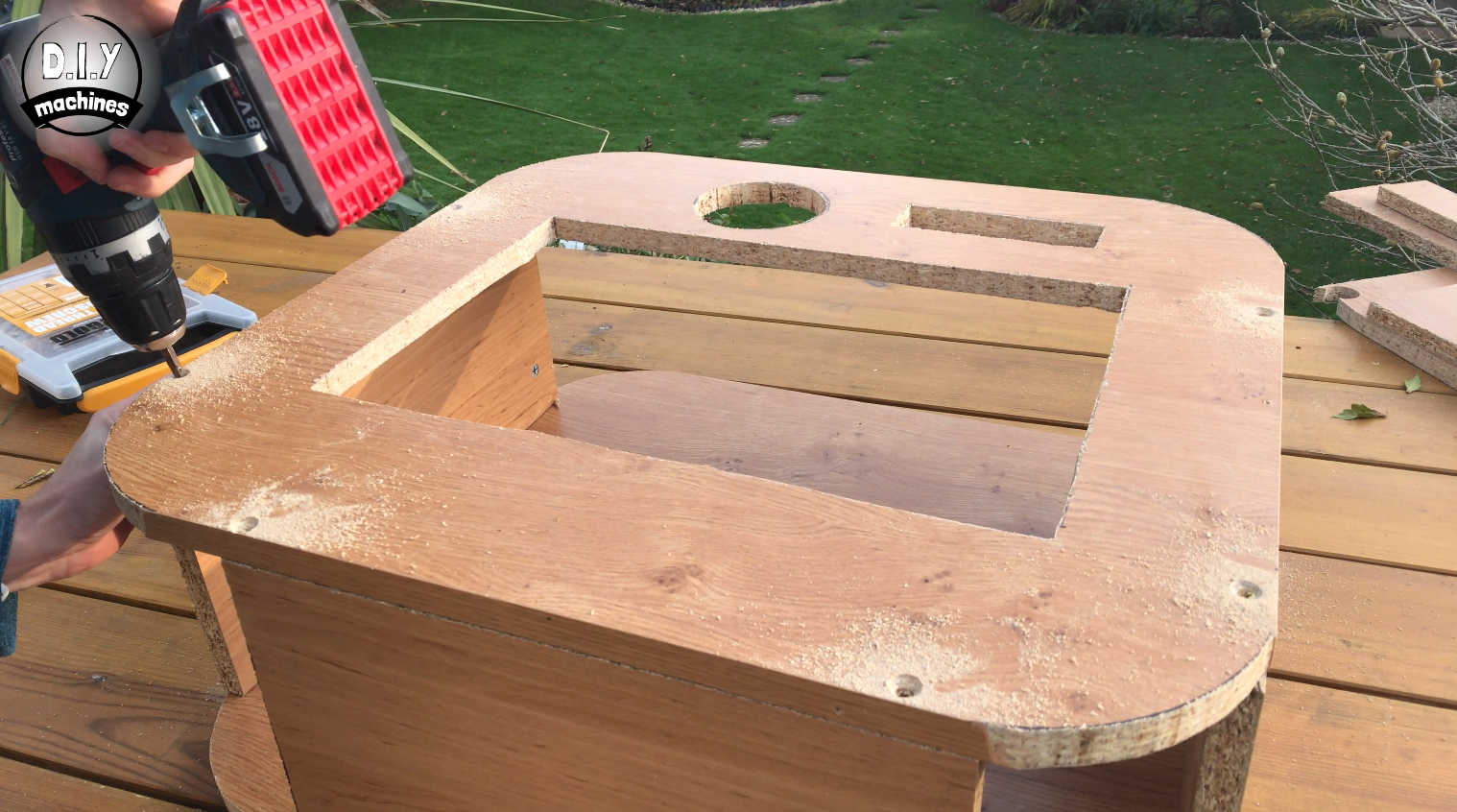
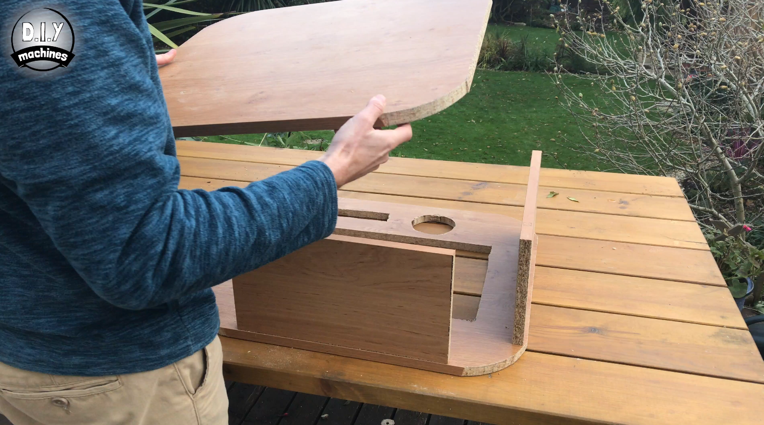
The housing is best assembled by laying the front down on a surface then placing the two 200 x 420mm boards standing up on their long edges on the perimeter of the board at either side. The smaller piece is then positioned along the bottom.
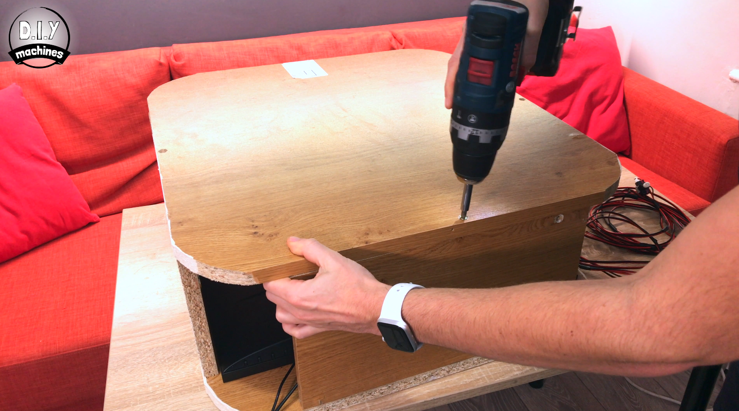
You can then lower the back on top of these and, after checking they are all aligned, screw them together with countersunk wood screws. You need to countersink them if you want to cover them when you decorate it later. Once this has been done carefully turn the housing over and screw on the front face.
At this point, you should be able to stand it up like mine in the photo above.
Step 6: Decorating - Filling, Sanding, and Painting
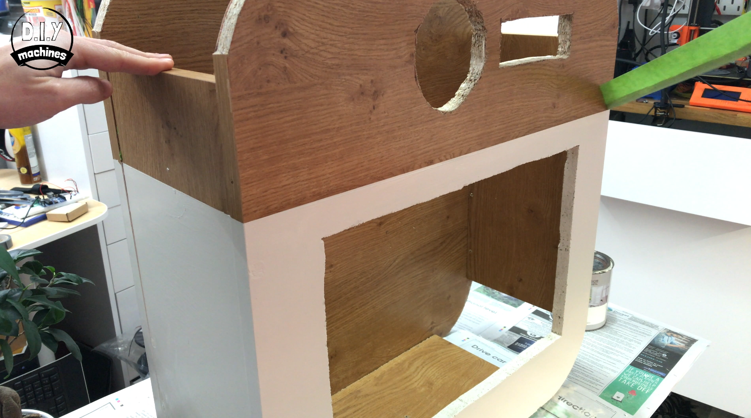
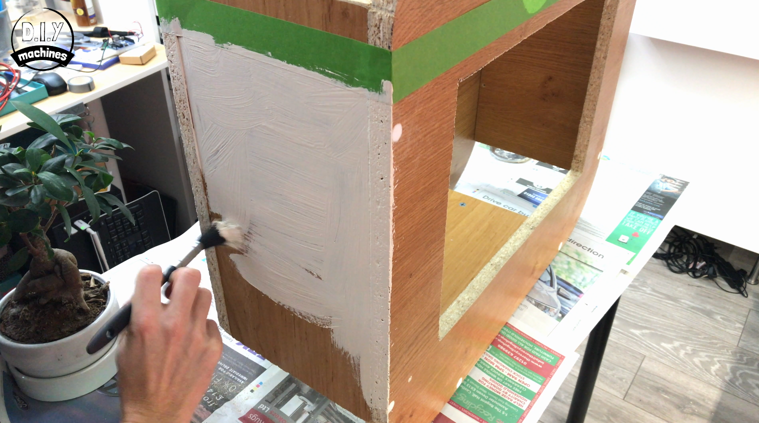
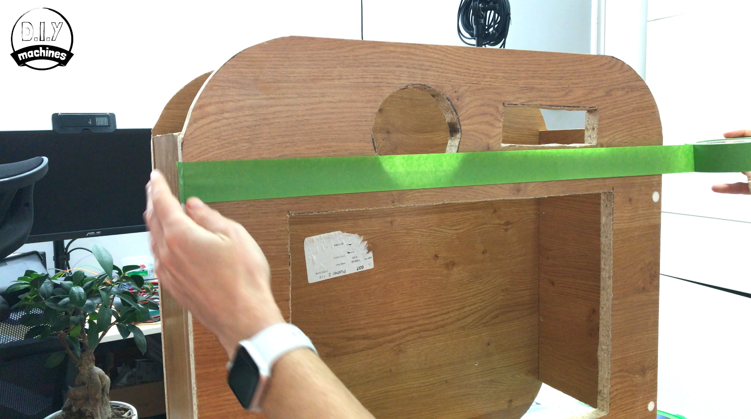
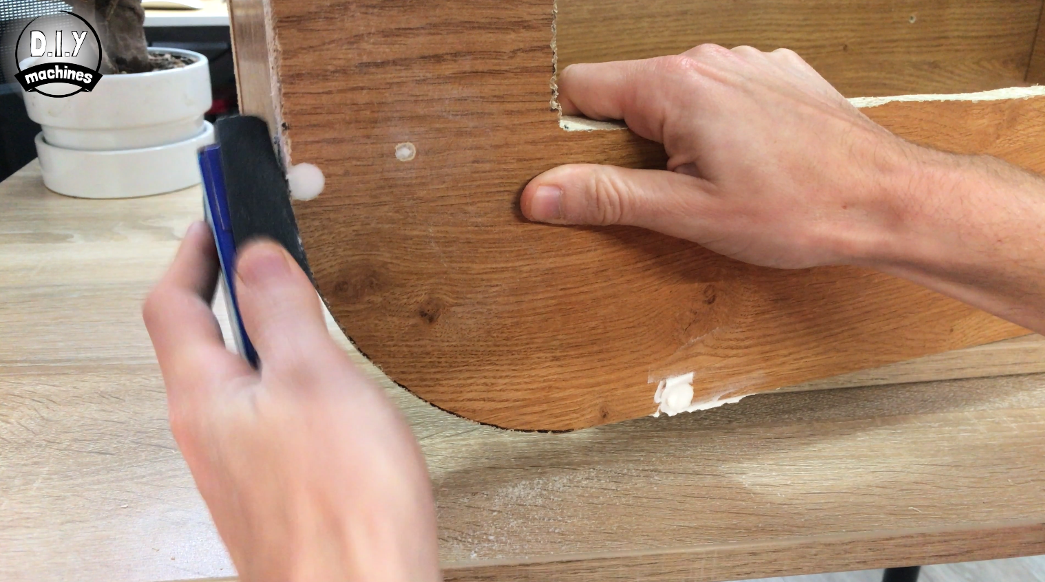
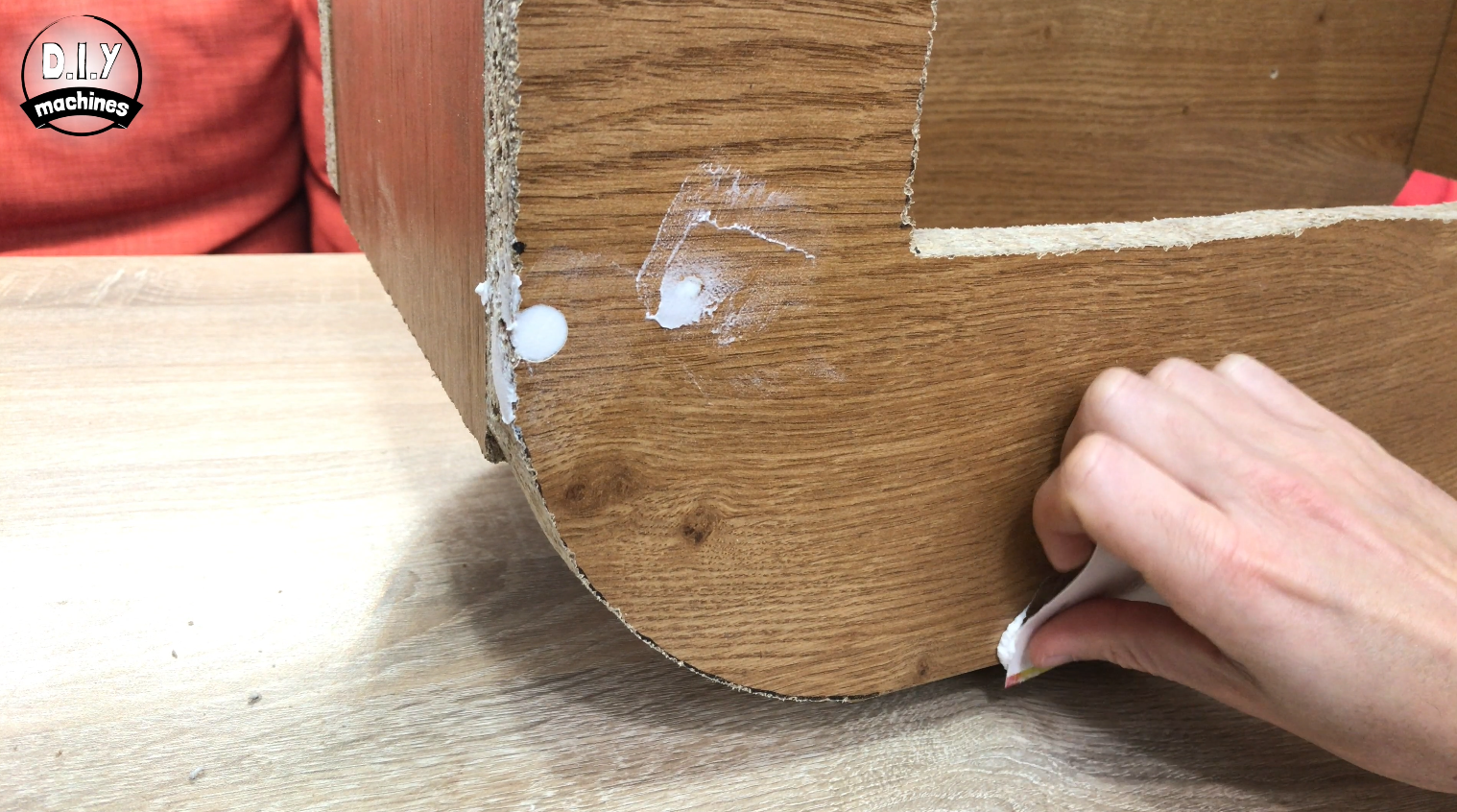
You can now cover the screw holes on the front panel with Polyfilla and once that has set, sand it down flush. Only cover the screw holes on the front side of the photo booth as we will need to remove the back later to access inside the photo booth.
I have then chosen to paint the lower two-thirds of my photo booth in a rice-like colour. To do this I masked of the top third with some tape and applied three coats of paint to it (allowing time to dry between each coat).
Step 7: Decorating With 3D Printed Trims
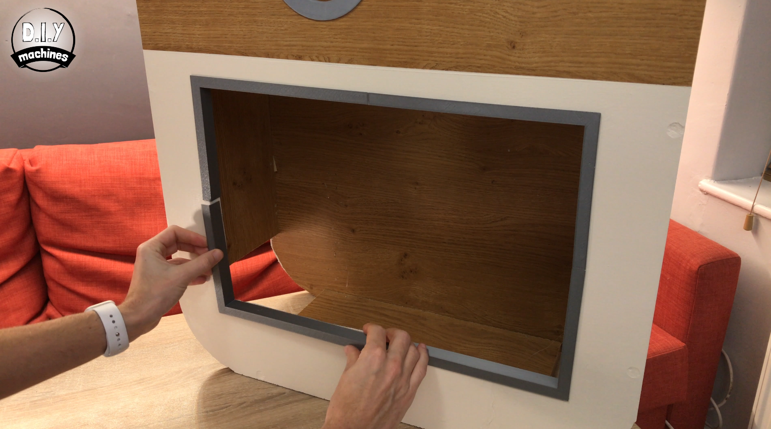
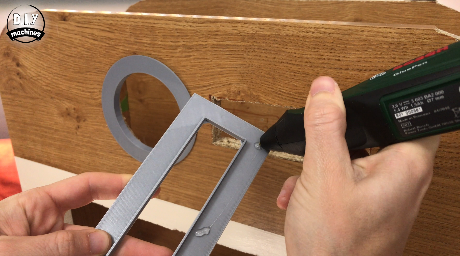
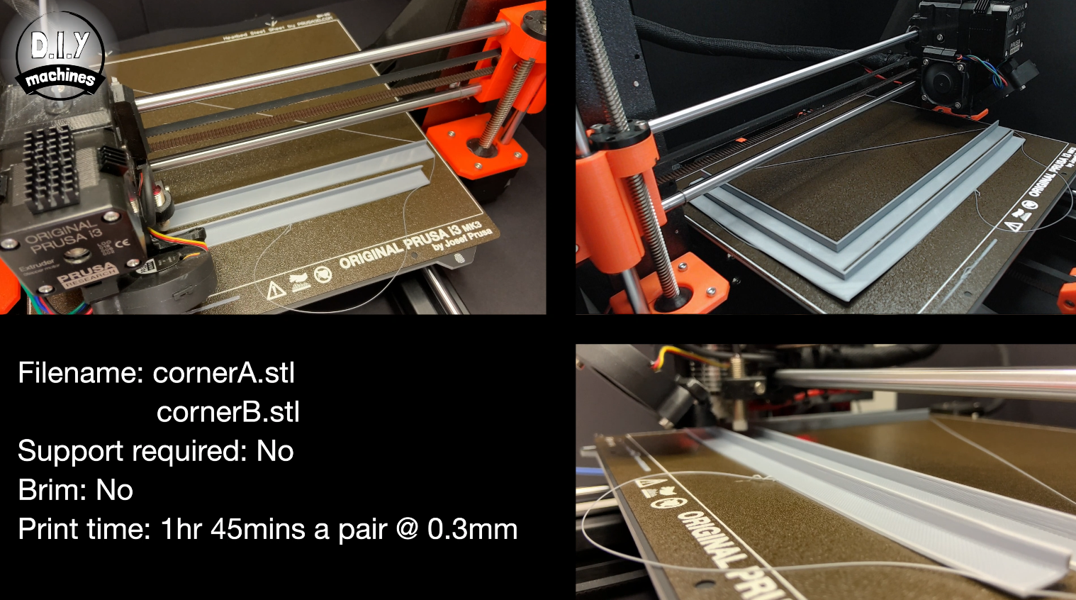
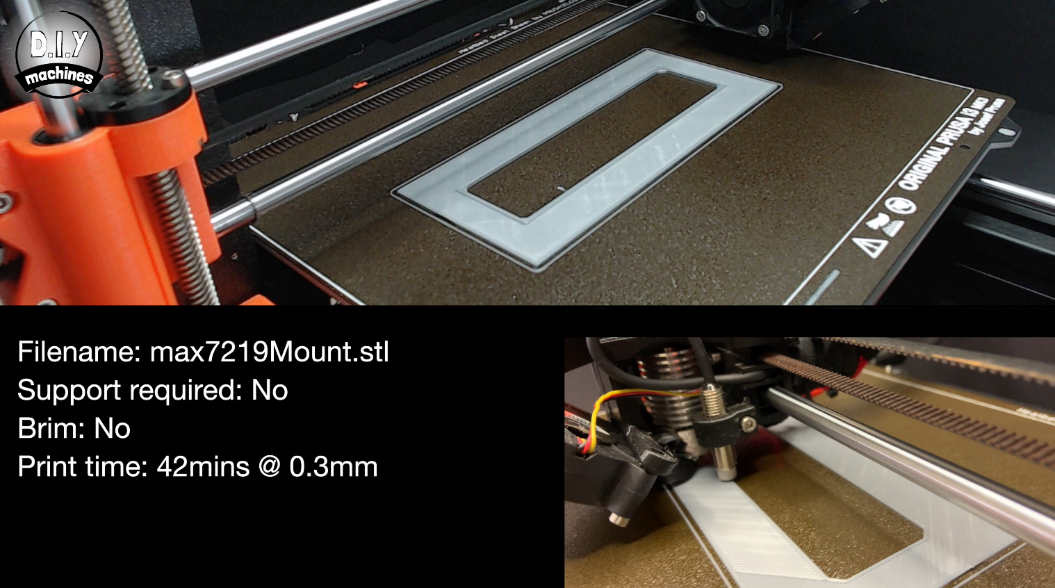
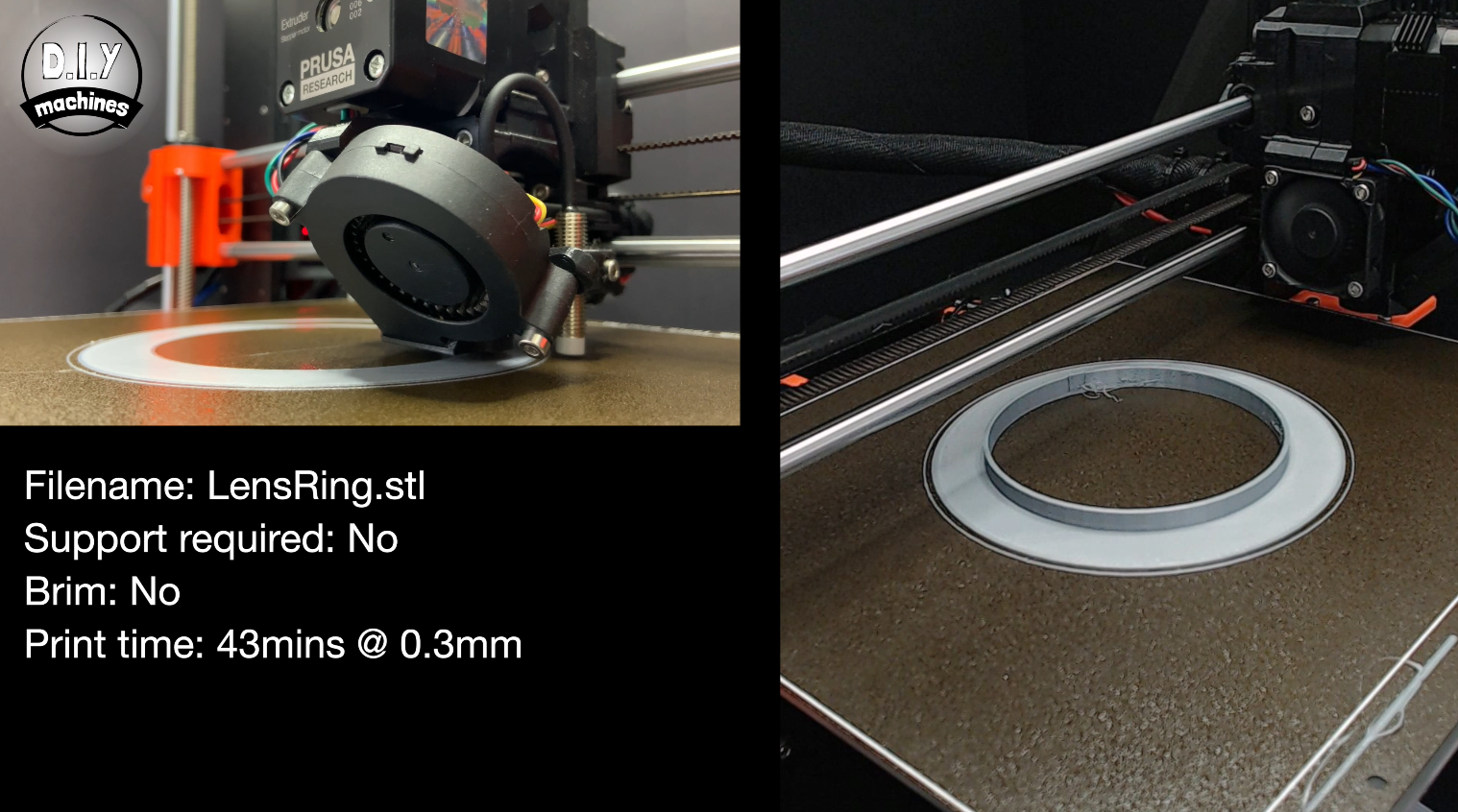
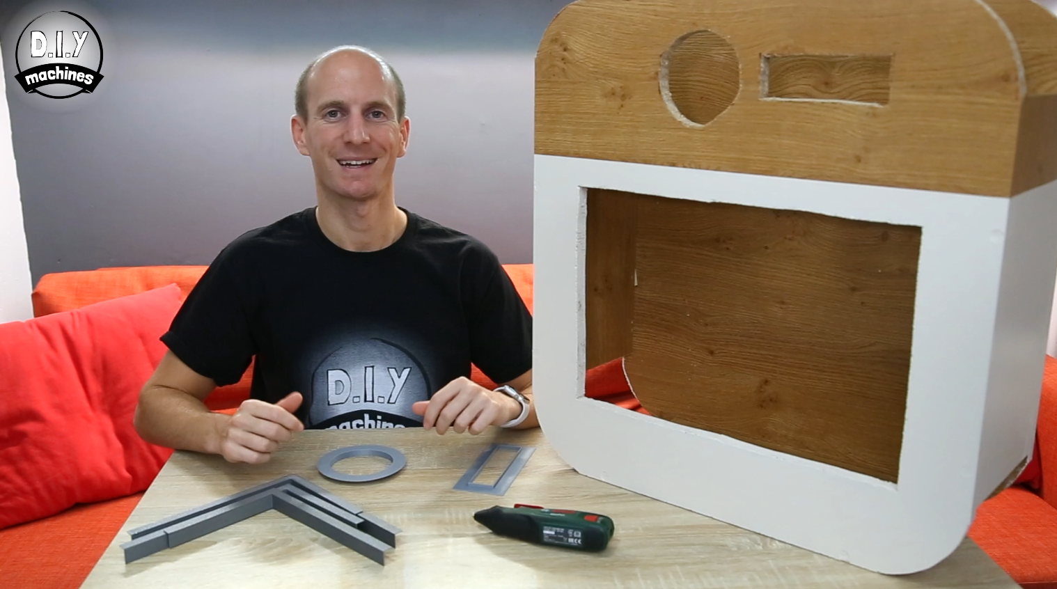
To help cover the rough cuts we made earlier you can print the attached STL files to get a set of trims to glue in place. I found that this greatly enhances the visual quality of the final build.
I chose to print all of mine in grey but feel free to choose any colour (or combinations of colour) you wish.
You need to print the following files just once:
- lensring.STL (43 minutes to print)
- max7219mount.STL (42 minutes to print)
These two files will need printing twice each (to get the four corners of the monitor trim):
- cornerA.STL (1hour 45mins a pair)
- cornerB.STL (1hour 45mins a pair)
I printed all of mine at a layer height of 0.3mm without any supports. You may need to add a brim if you have difficulty printing the corner pieces.
Once the prints are complete and the paint has dried you can fix them into place with some hotmelt glue.
Step 8: Prepare MAX7219 LED Display
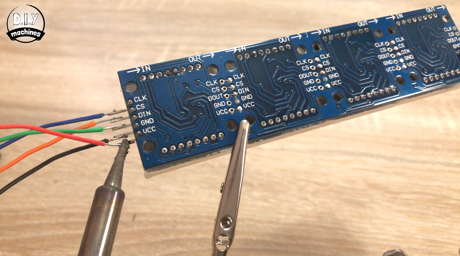
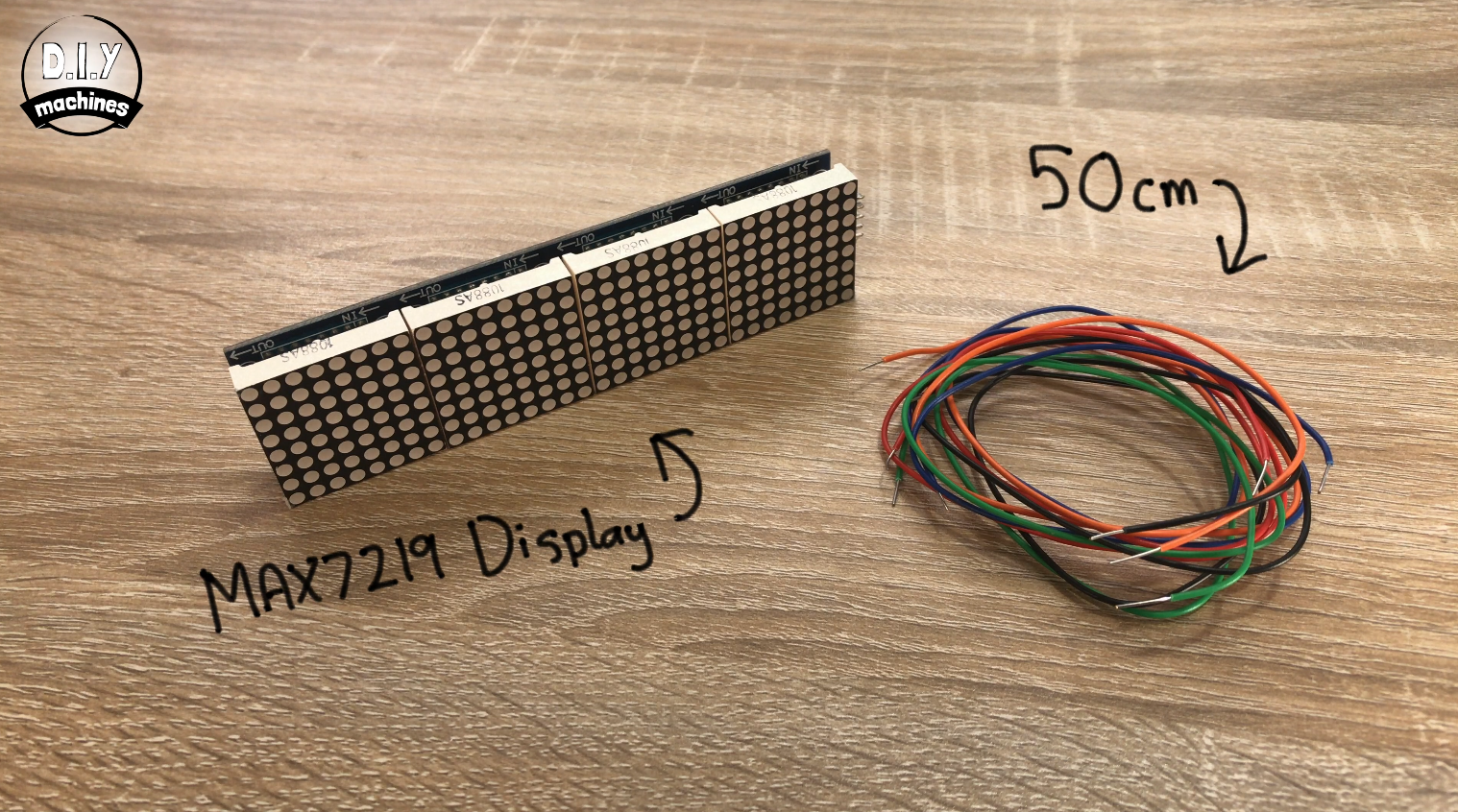
Prepare and solder five 50cm lengths of hook up wire (about 22 AWG) to the five male pins at the end of the display module.
Step 9: Prepare Arcade Button
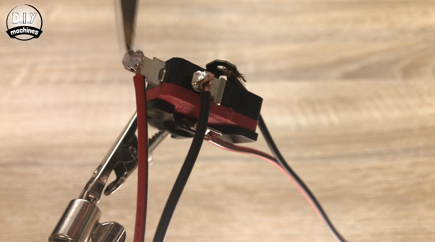
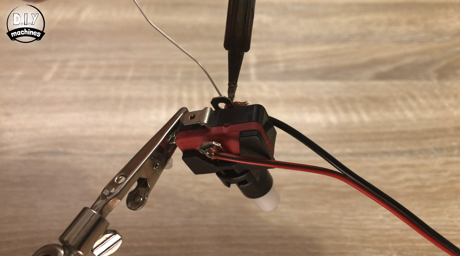
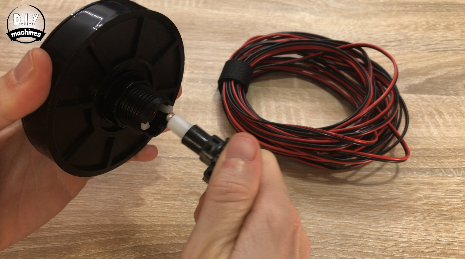
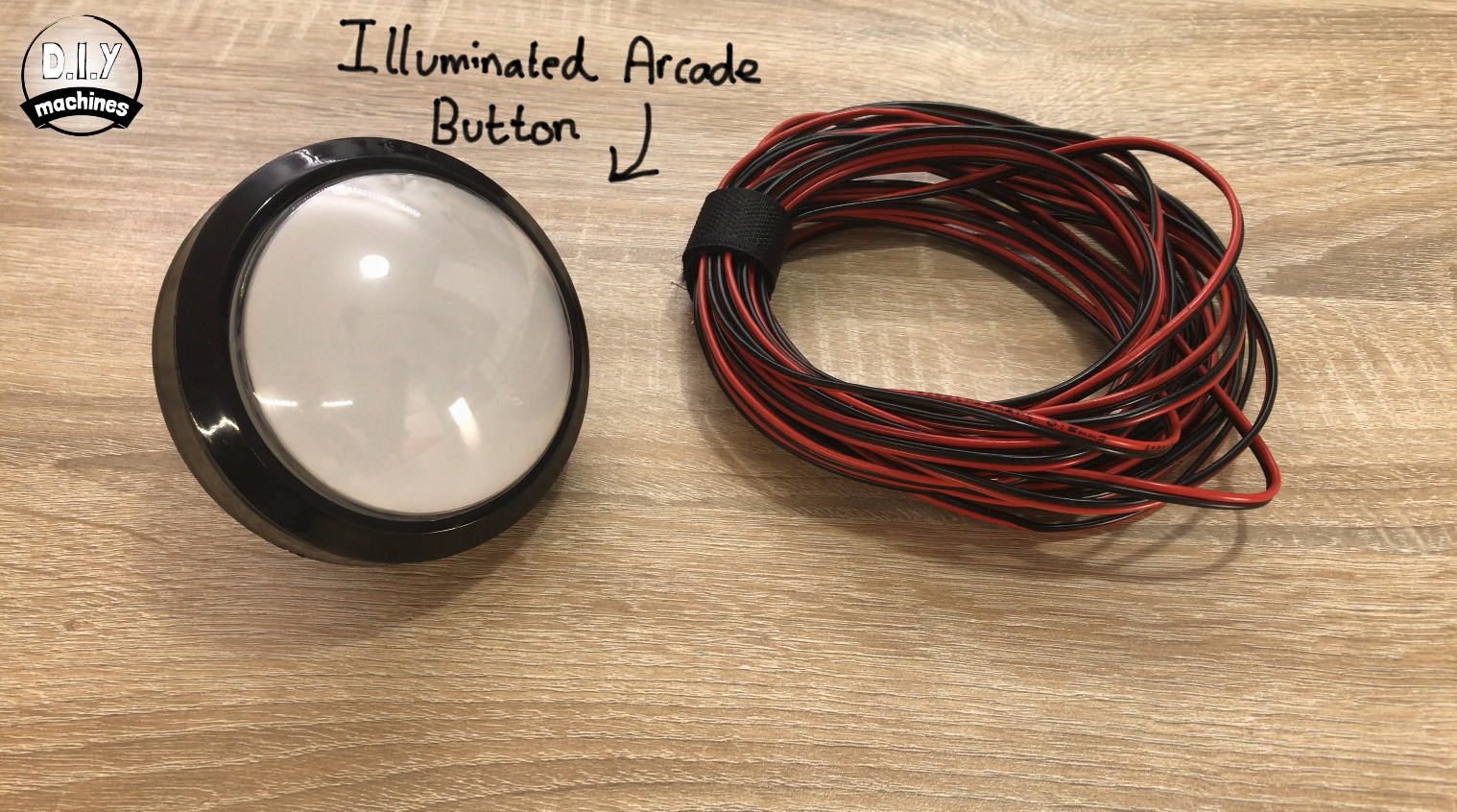
Remove the electronics from the arcade button by gently turning and pulling them from the base. This will make it easier to handle whilst working with.
I used some 4m lengths of speaker wire to connect the button to the photo booth as this allowed me to put the button further in front of the photo booth to keep party guests back from the photo booth itself. :)
Solder a separate wire to each of the four available connections. The two inside ones are for the switch and the two outside ones are for the LED. If later you find you have the polarity wrong you can just lift the bulb out of its holder and reinsert it the other way round.
Step 10: Prepare Shutter Cable
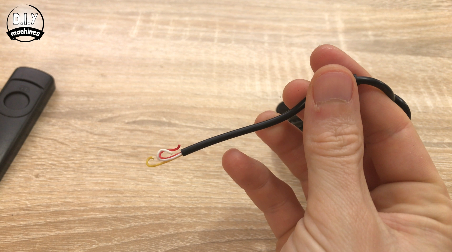
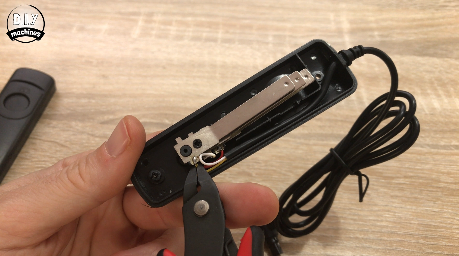
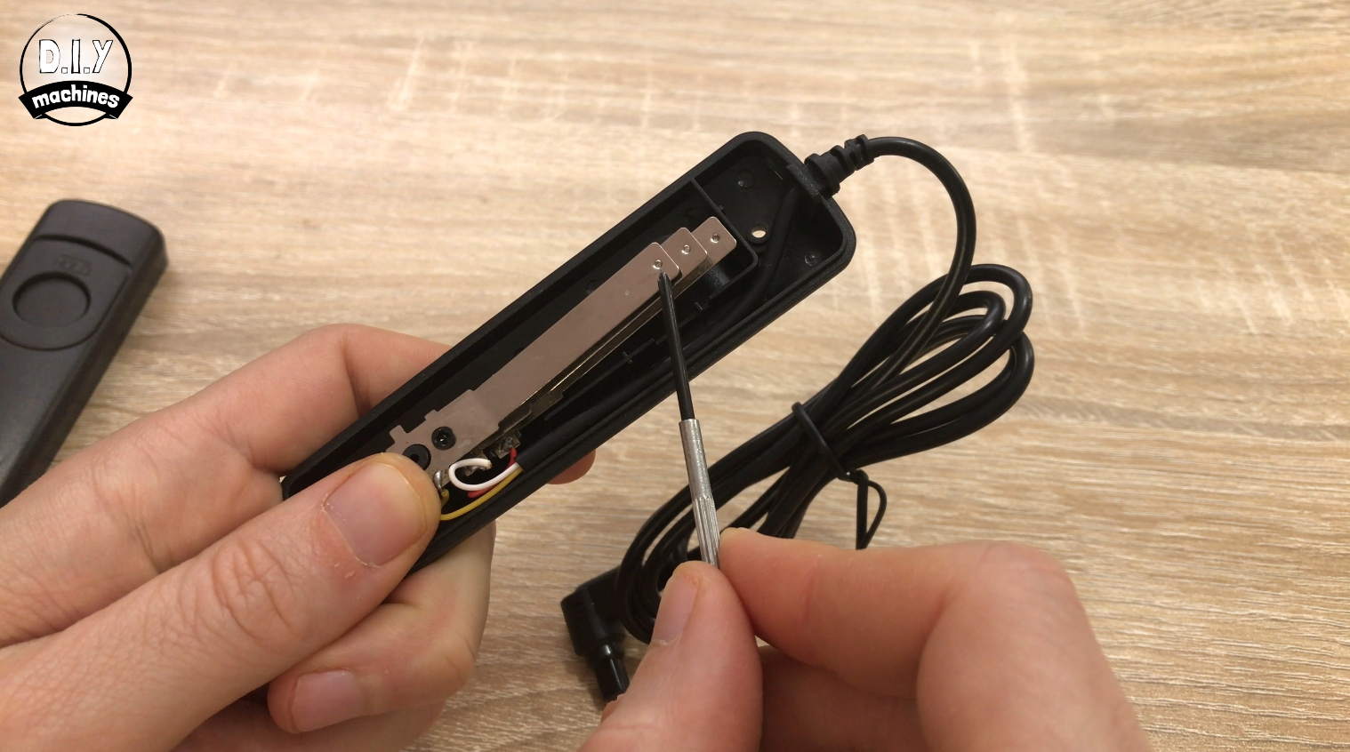
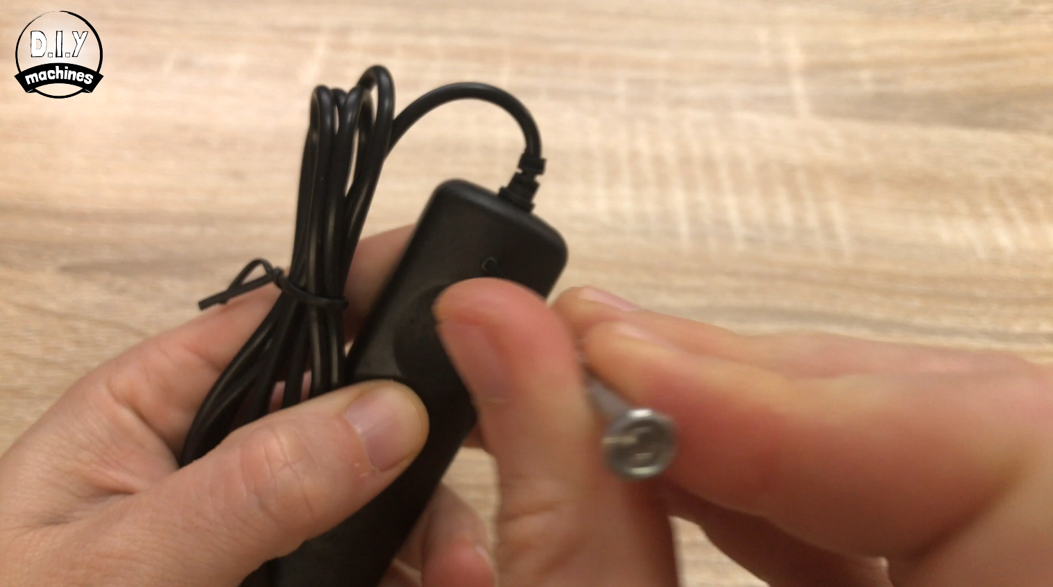
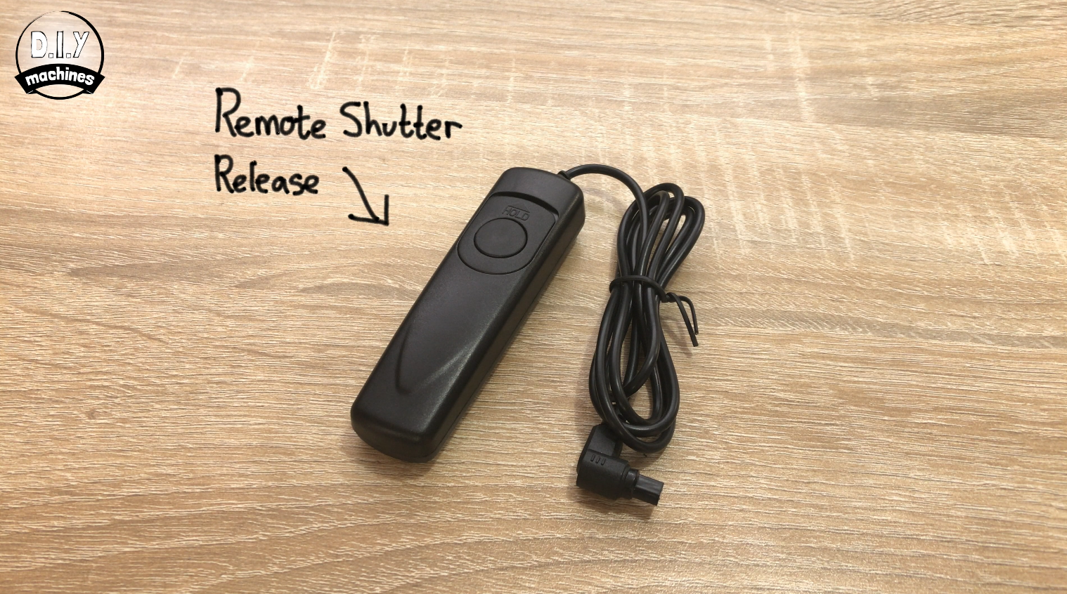
Now we can open up the shutter release cable and take note of which wires are connected to what.
For the shutter release I had for my Canon camera I just had to remove one small screw from the back and prise it carefully open. Inside you should find three metal plates. Write down (or take a photograph) of which wire is connected to which plate. Yours may not be the same as mine.
With mine, the top plate 'focus' plate is connected to the yellow wire. The middle 'ground' plate is connected to the red wire and the bottom 'shutter' plate is connected to the red wire.
When the focus or shutter plate makes contact with the central ground plate it triggers that step on the camera.
After you have a note of the wiring, carefully cut the wires away from the metal plate. We only need to keep the cable itself. The plates and housing should be recycled.
Step 11: Assembling the Circuit
I assembled the circuit for this project (as most people would) on a breadboard first. Then after the wedding I decided to have a go at soldering the components onto a piece of perforated board.
In the next step, I'll guide you through assembling the electronics on the breadboard as I did first. If you would rather assemble the electronics onto a piece of perforated board then skip ahead a step. :)
Step 12: Assembling Electronics on a Breadboard
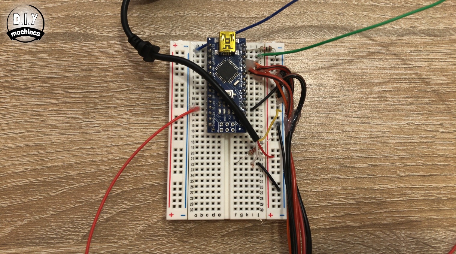
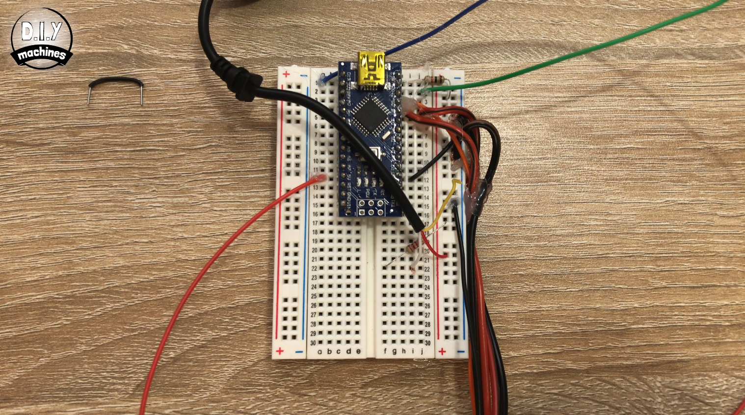
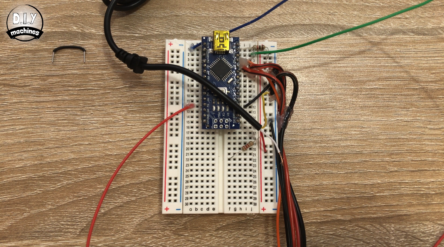
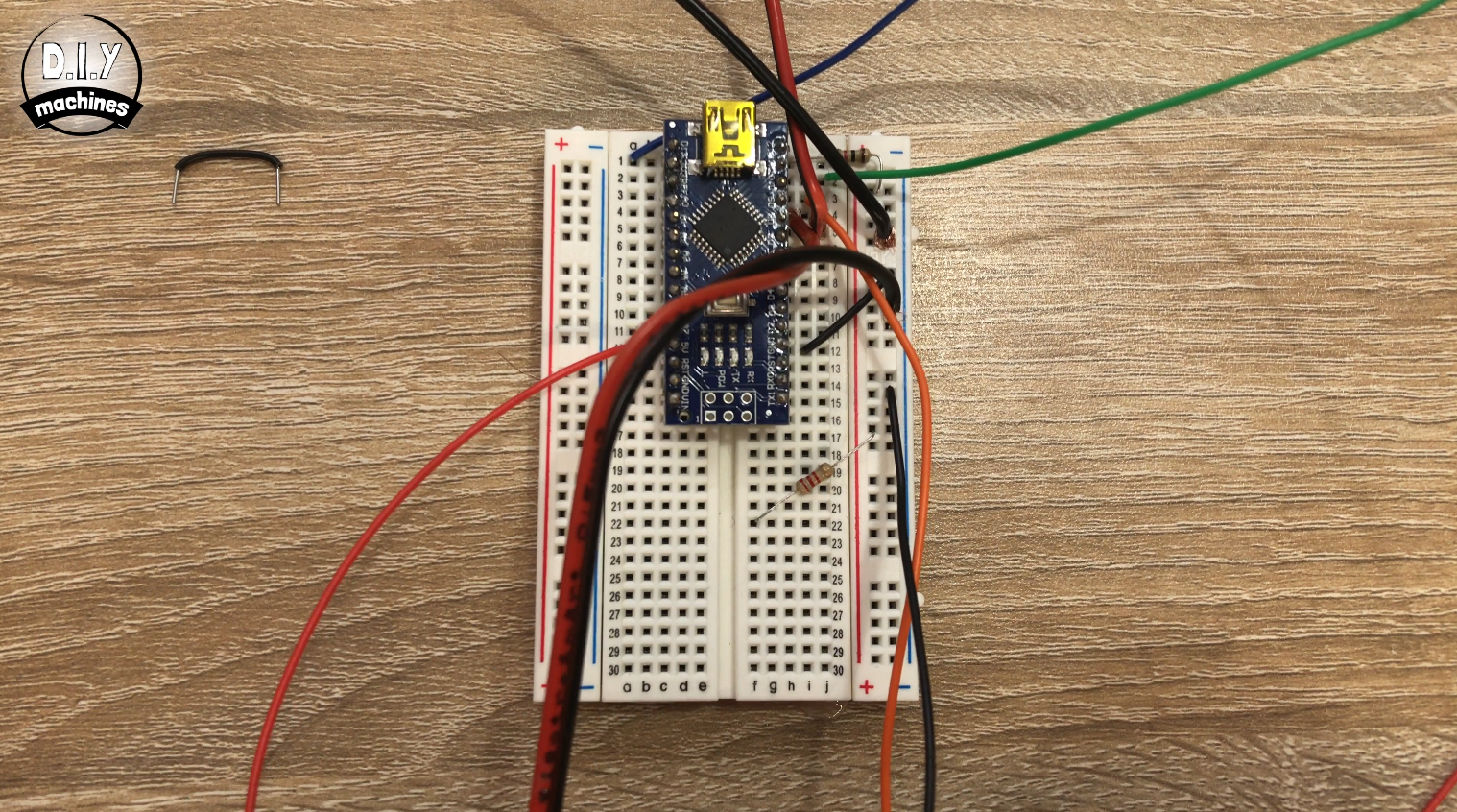
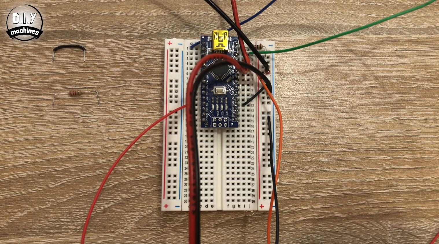
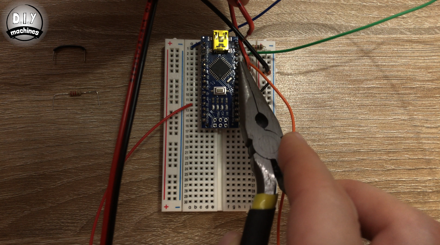
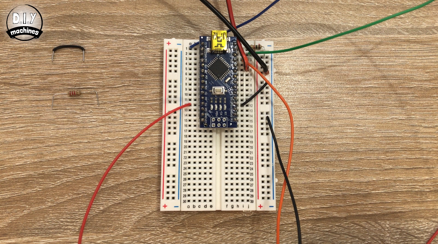
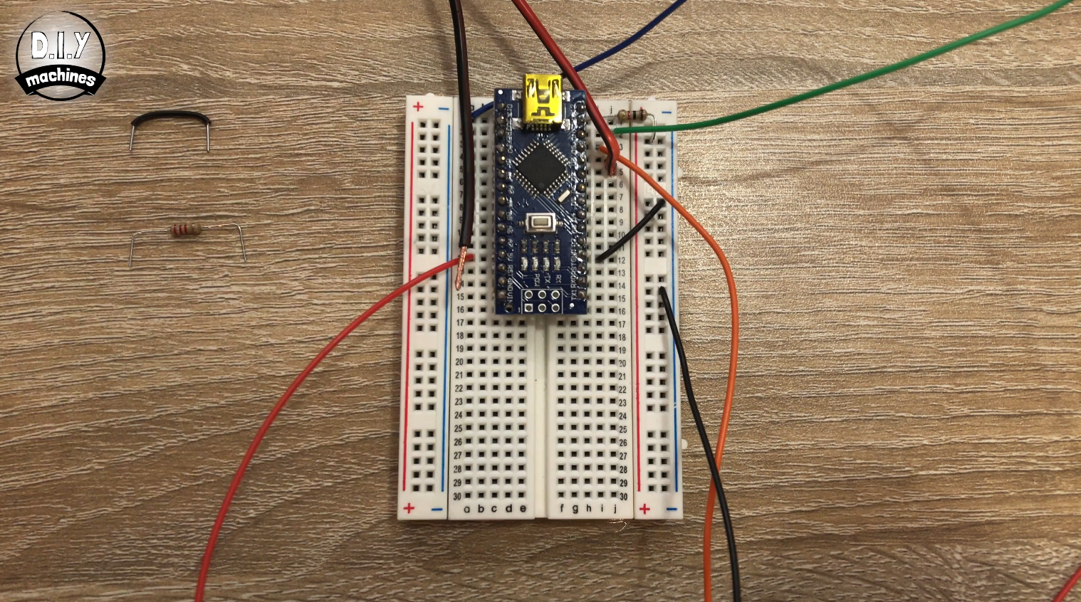
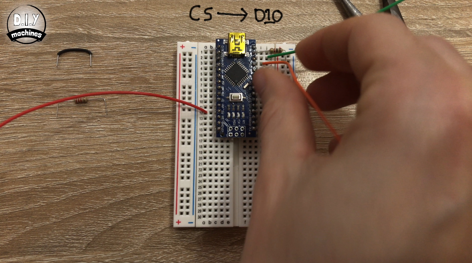
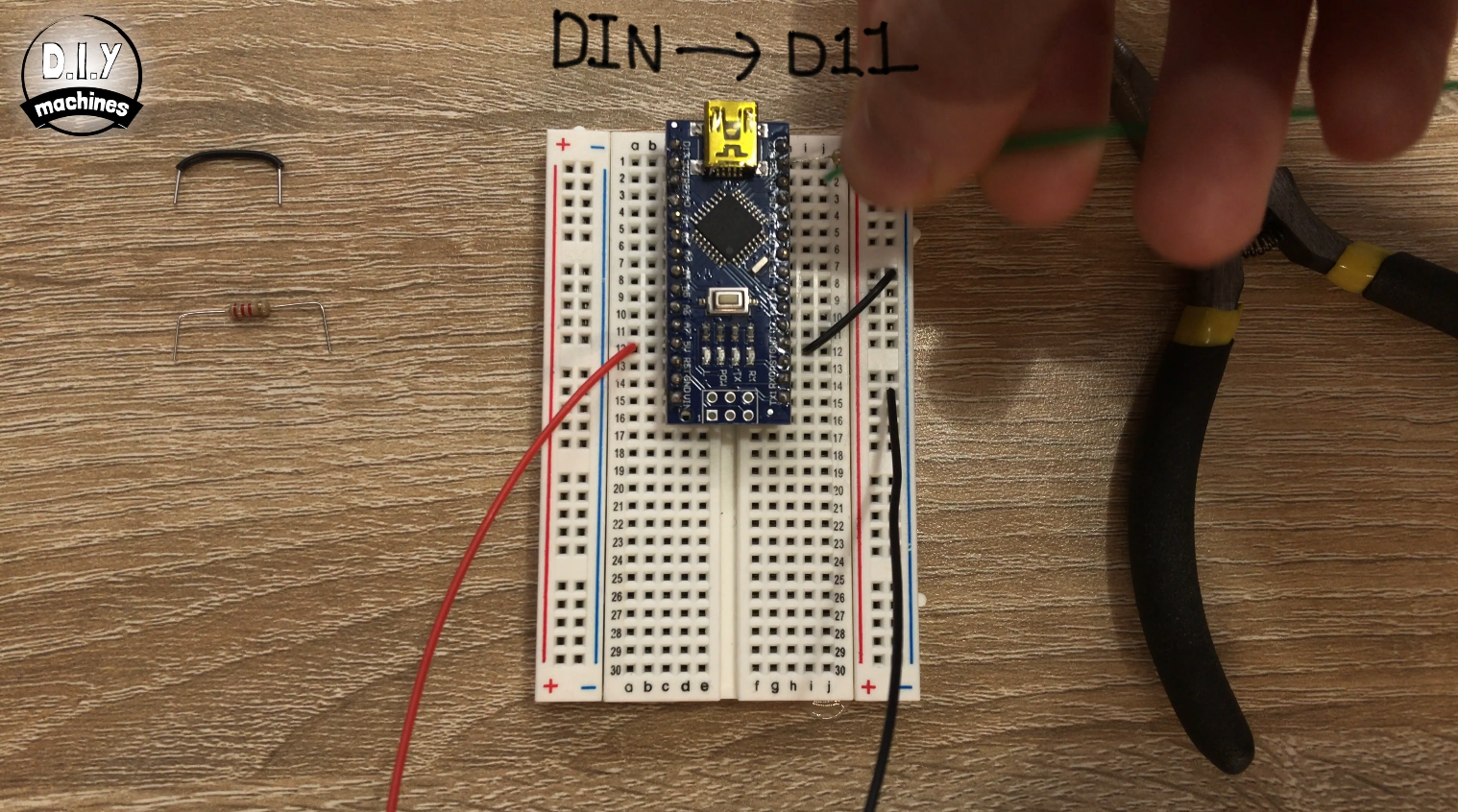
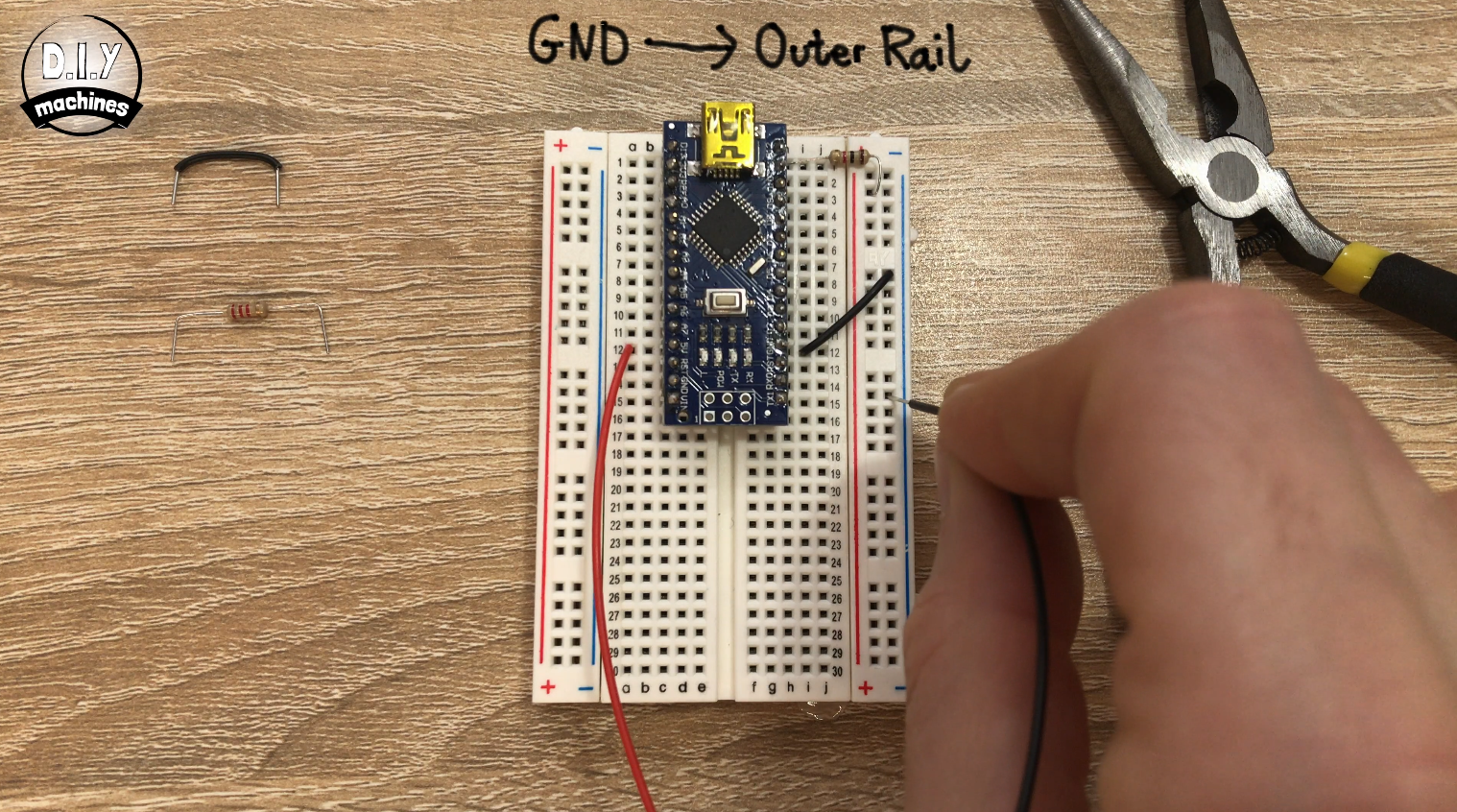
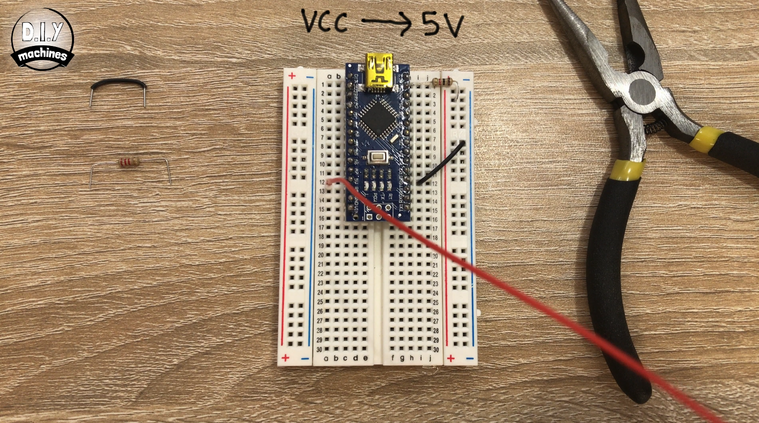
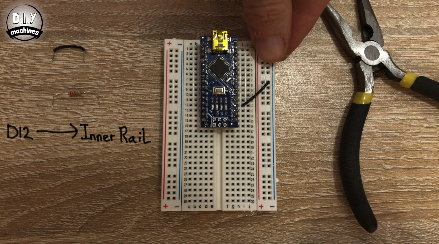
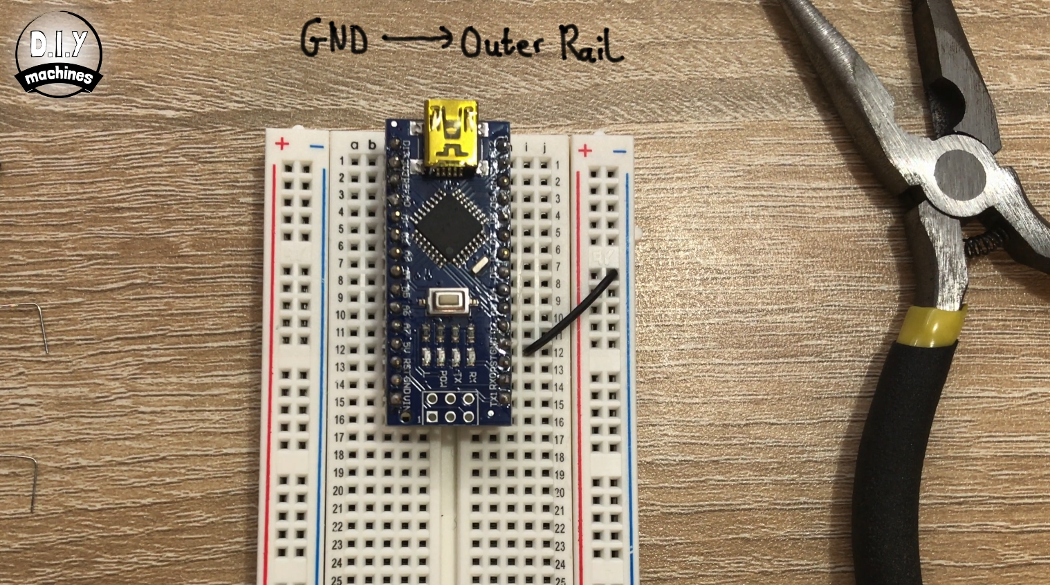
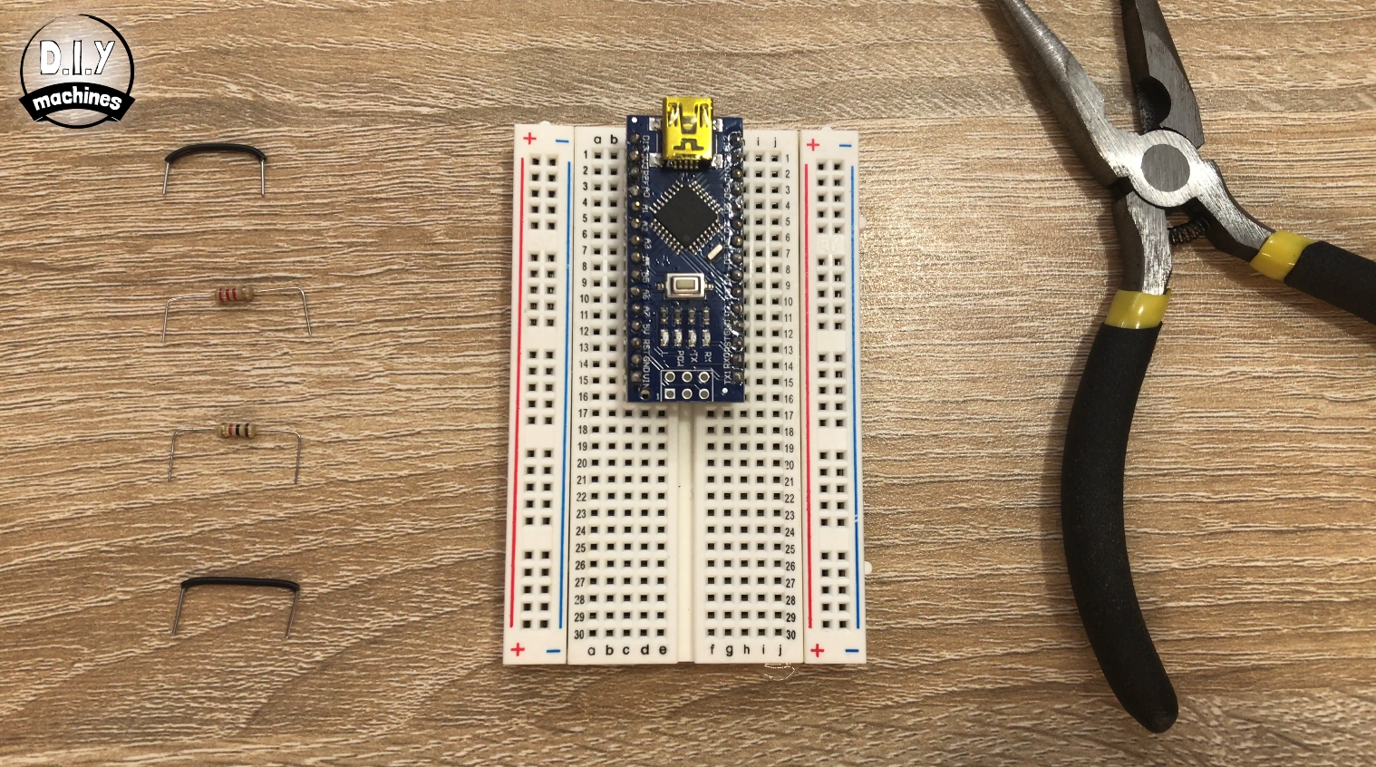

Place your Arduino Nano at the top of the board so that its pins straddle the central divide.
Use a short length of wire to connect the ground connection to the outside rail.
Connect the 1k resistor (Brown-Black-Red) between pin D12 and the inner rail.
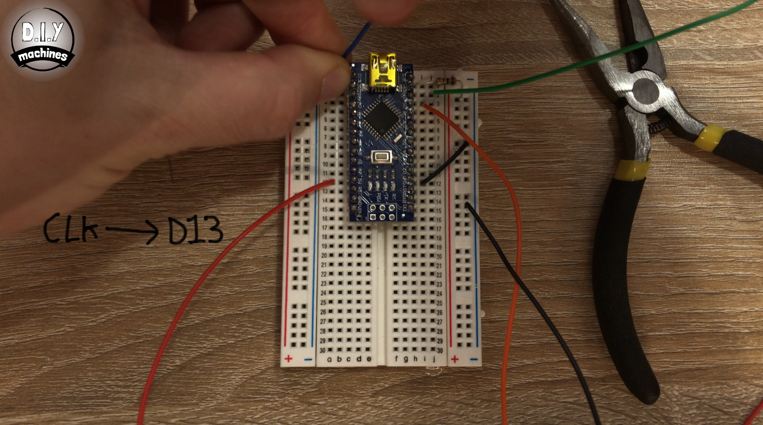
To connect the LED MAX7219 display to the breadboard connect:
- VCC -> 5v
- GND -> Outter ground rail
- DIN -> D11
- CS -> D10
- CLK -> D13
Once wire coming from the arcade buttons switch should be connected to D8 whilst the other wire is connected to the outer ground rail.
The positive wire from the buttons LED should be connected to D9 and the other to the outer ground rail.
Position the 2.2k resistor between the inside rail and one of the spare rows at the end of the breadboard.
At this point, I stopped and used some hot melt glue to secure some of the cables in place.
Connect the wire which was coming from the bottom plate inside the shutter release to the inside rail (red in my case). The wire which was on the middle/ground plate should be connected to the same row you just connected the 2.2k resistor to. Finally, use one more additional length of wire to connect the ground rail to where the 2.2k resistor is connected to the middle/ground plate.
Step 13: Assembling Electronics on a Perforated Board
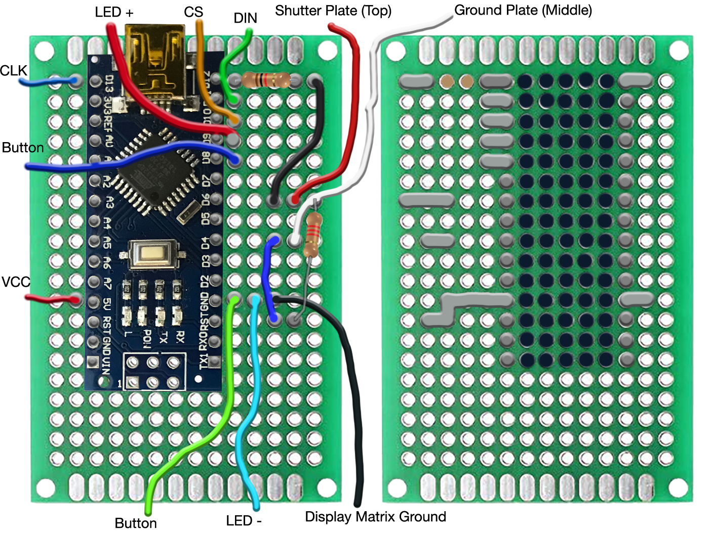
I have drawn a diagram for the perforated board which is attached to this step. The left-hand side shows you the view of the top of the board and the right-hand side shows the underside. When following, take care to notice where pins have been connected together with solder on the underside.
I have created a video to step you through these connection one by one. You can watch that clip here:
https://youtu.be/Fu5Gbpv4EYs?t=531
Step 14: Uploading the Code
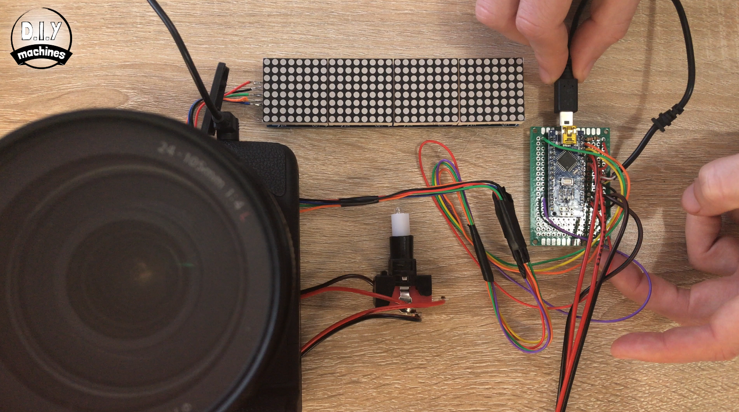
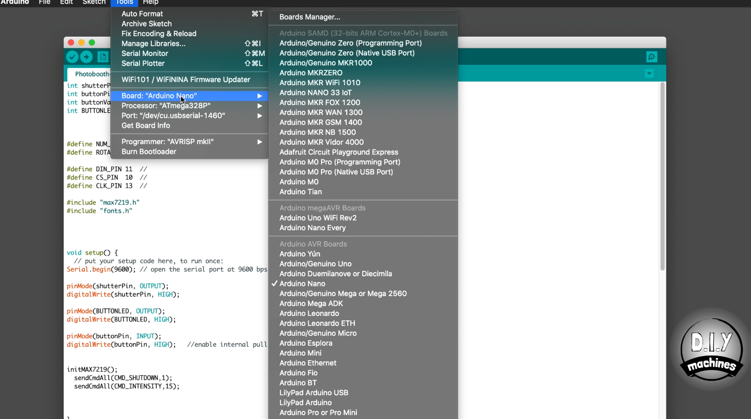
Connect your Arduino Nano to your computer using a USB cable.
Download the code for the project: https://github.com/DIY-Machines/PhotoBooth and open it in the Arduino IDE.
Select the board type of 'Arduino Nano' and processor ' ATmega328p'. Choose the serial connection for your Arduino and upload the code.
Step 15: Test the Electronics
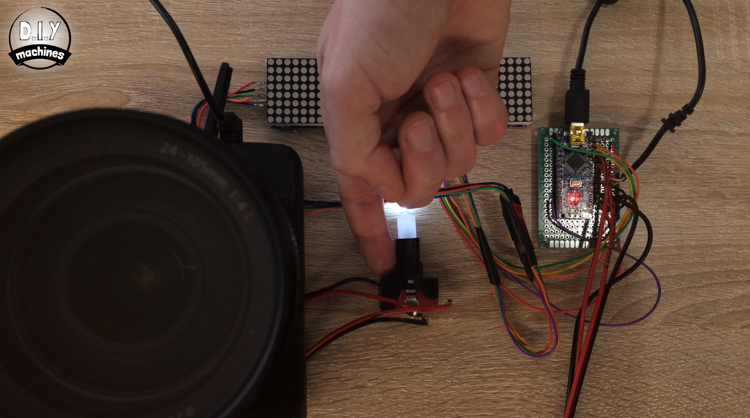
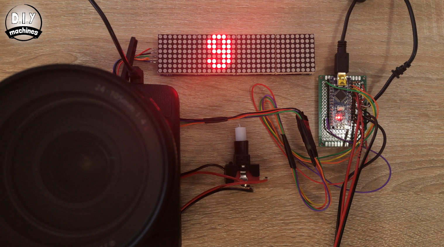
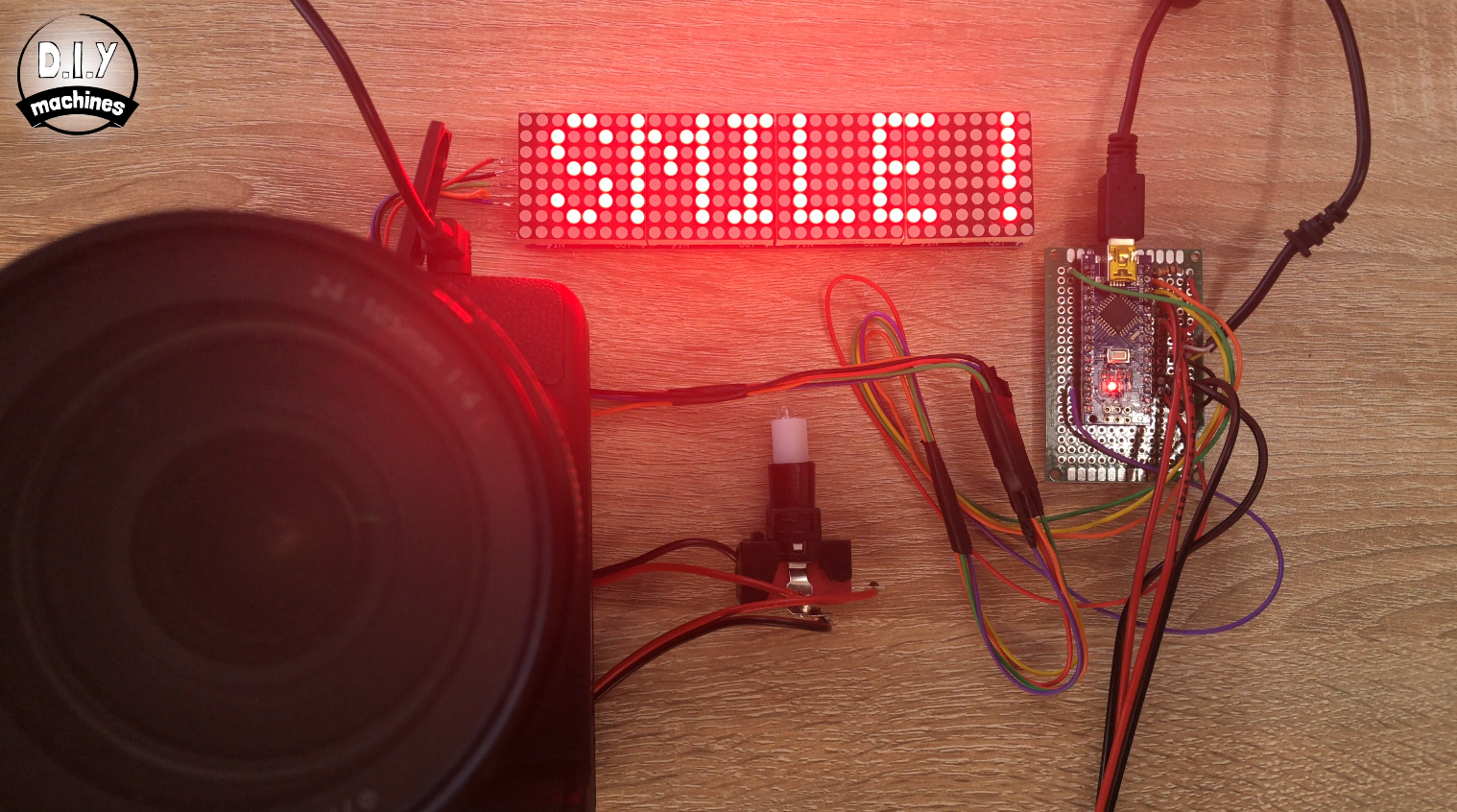
If everything is going well you can press the switch adjacent to the lit LED and the LED Matrix display should count down from 10 and then (if you have connected your camera) take a photo. If this repeats three more times without a hitch then we can proceed onto the next step. If something has not gone as expected now is a good time to troubleshoot before you go any further.
Step 16: Tidy the Wiring
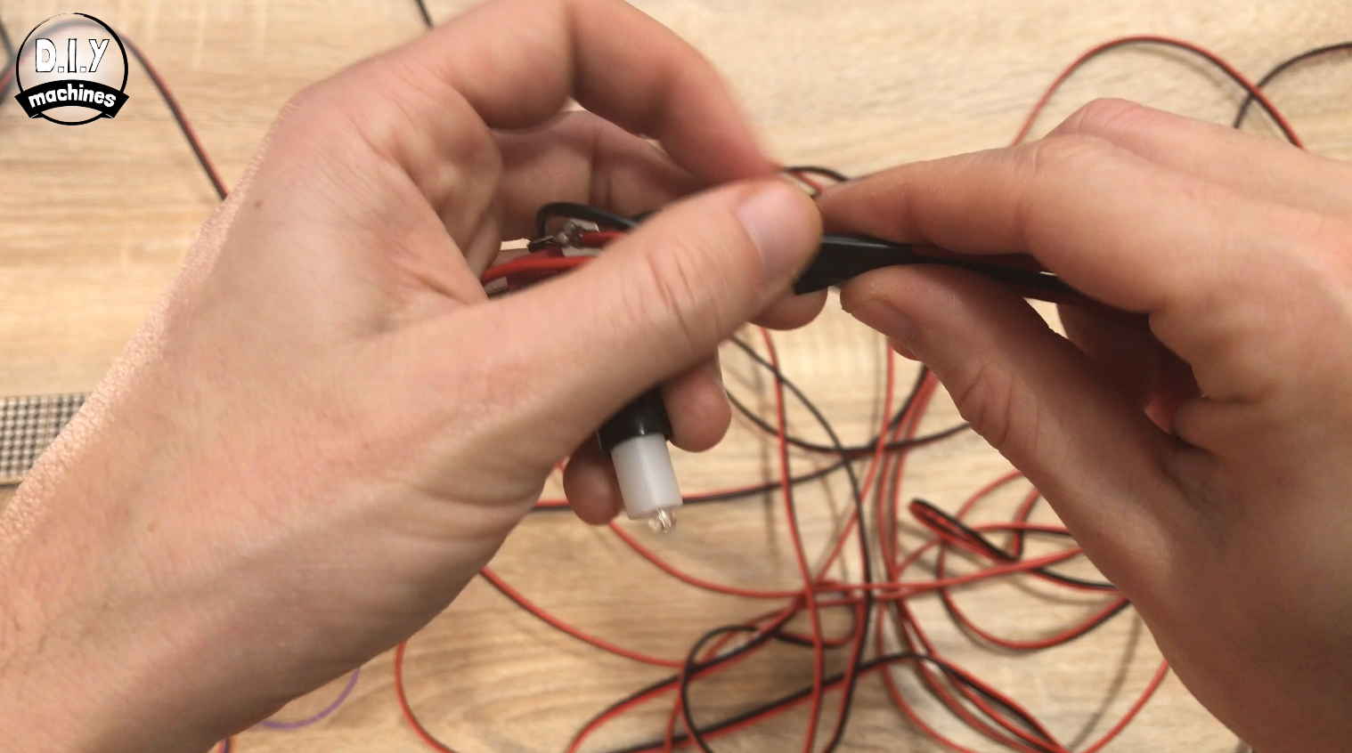
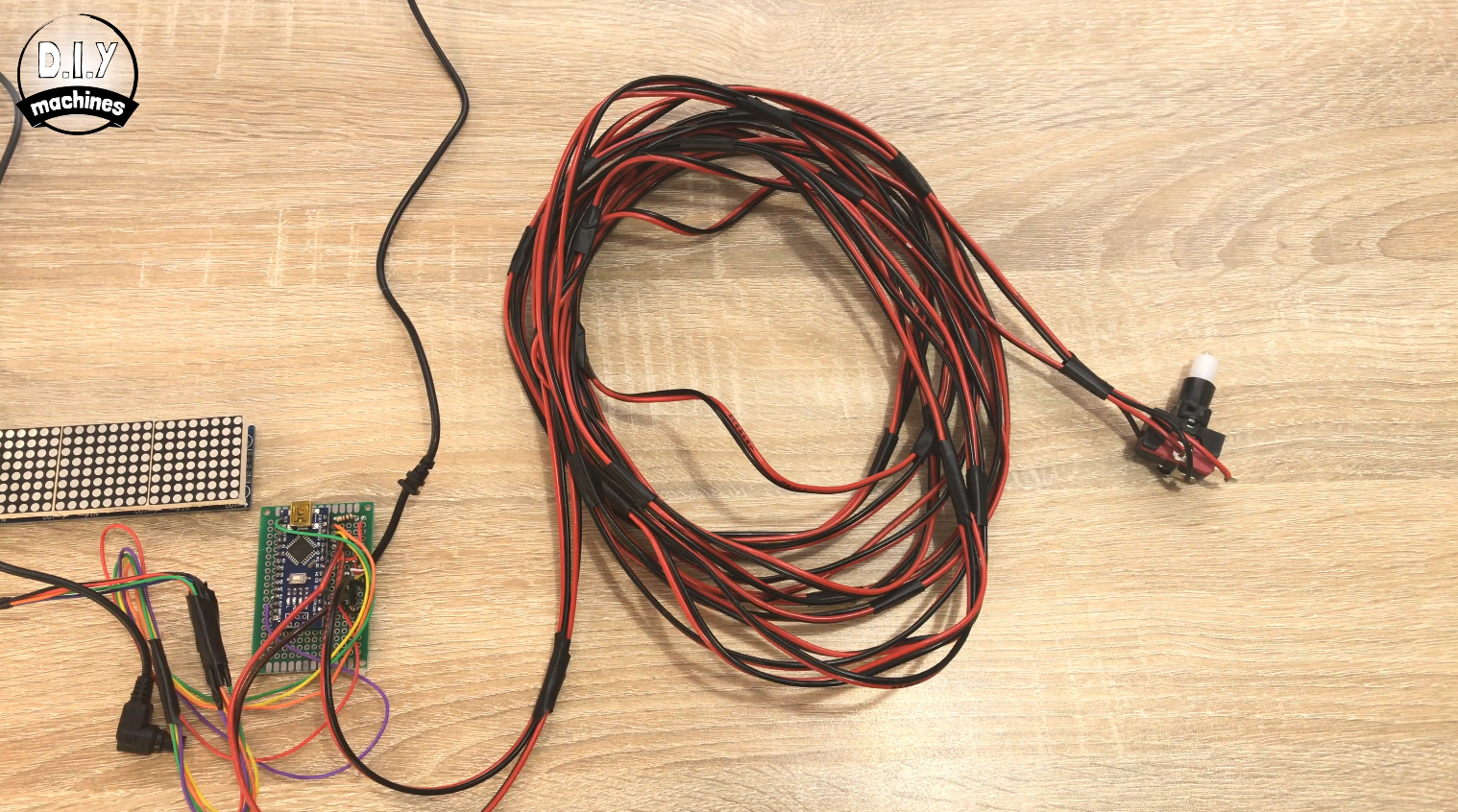
Where you have some long runs of wiring (such as between the electronics of the arcade button and Arduino) use some strips of insulation tape or similar to hold together the different peices of wire.
This will keep everything nicely untangled and more presentable.
Step 17: Mount the Camera
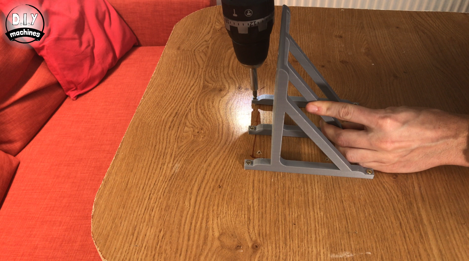
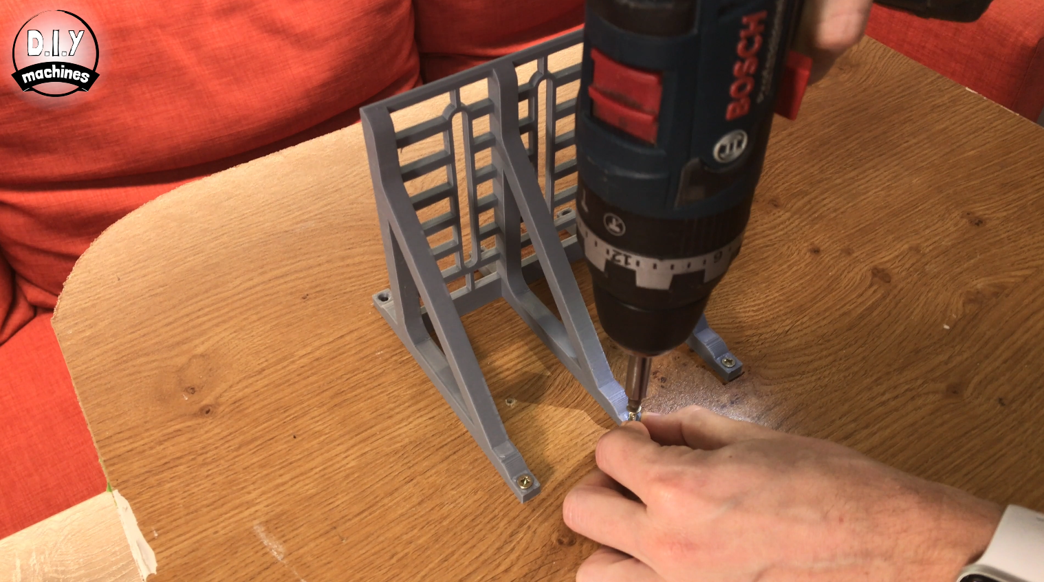
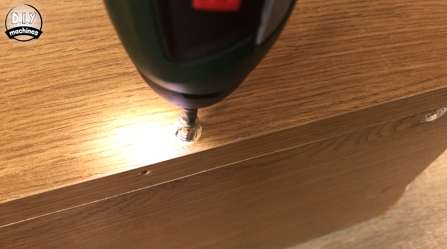
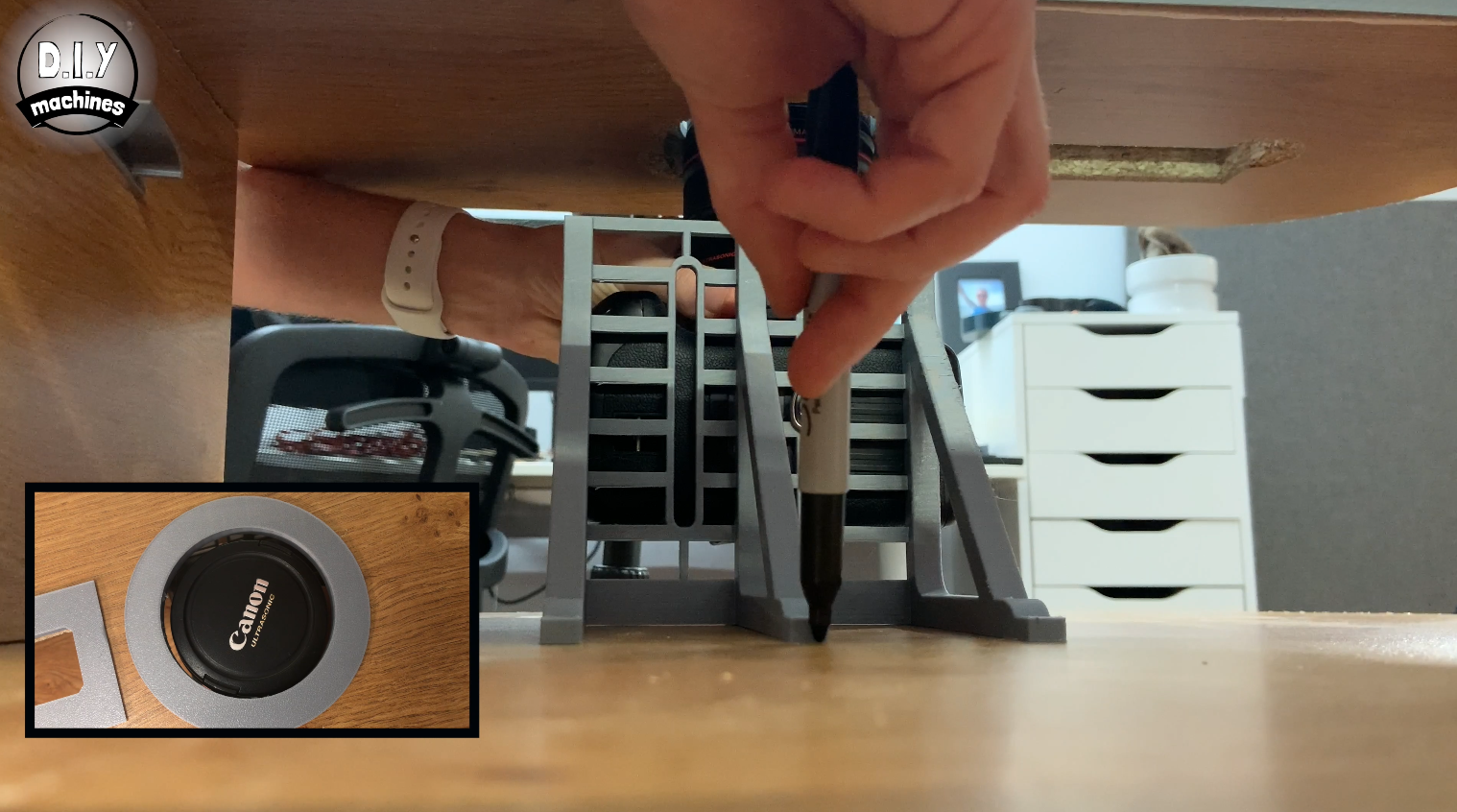
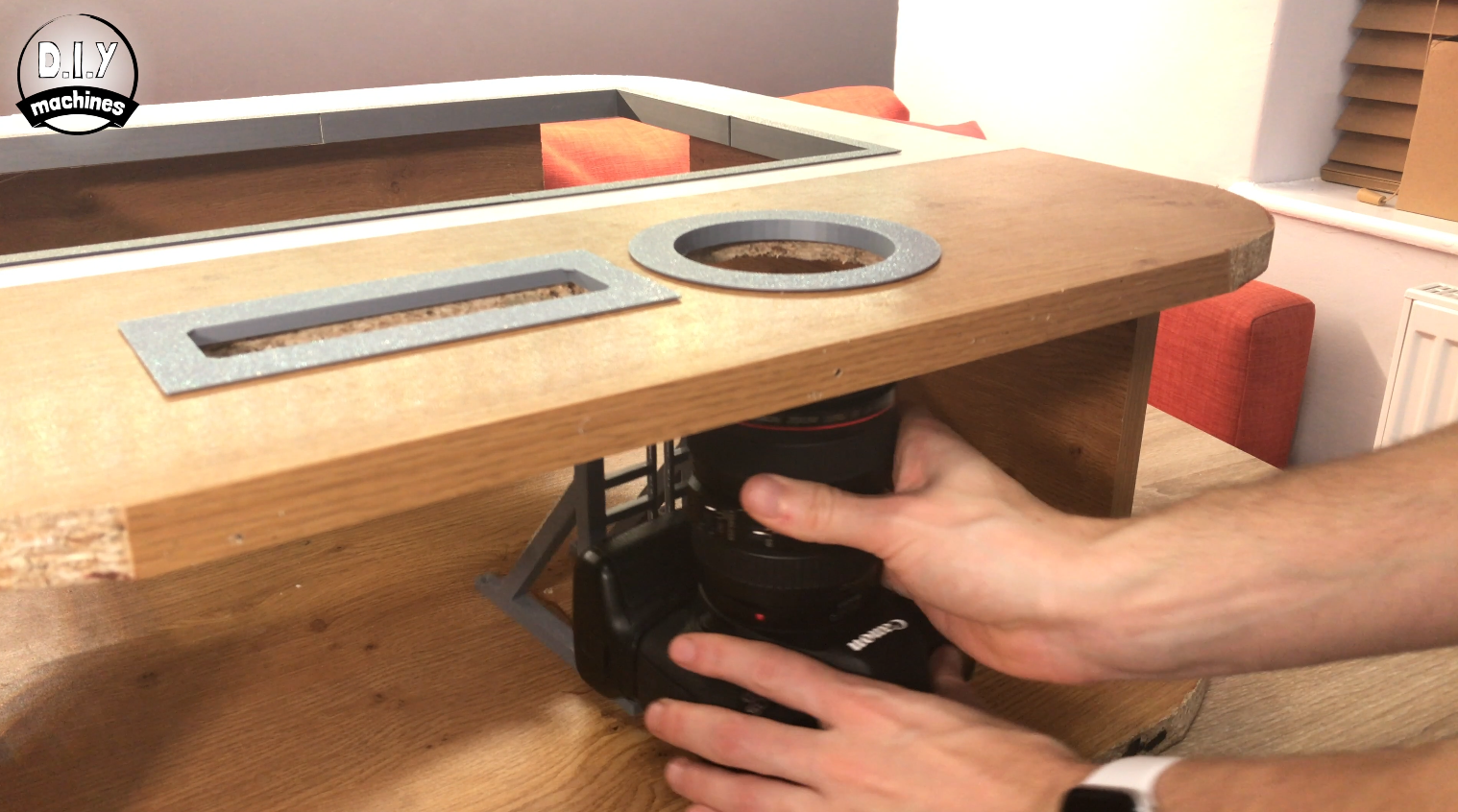
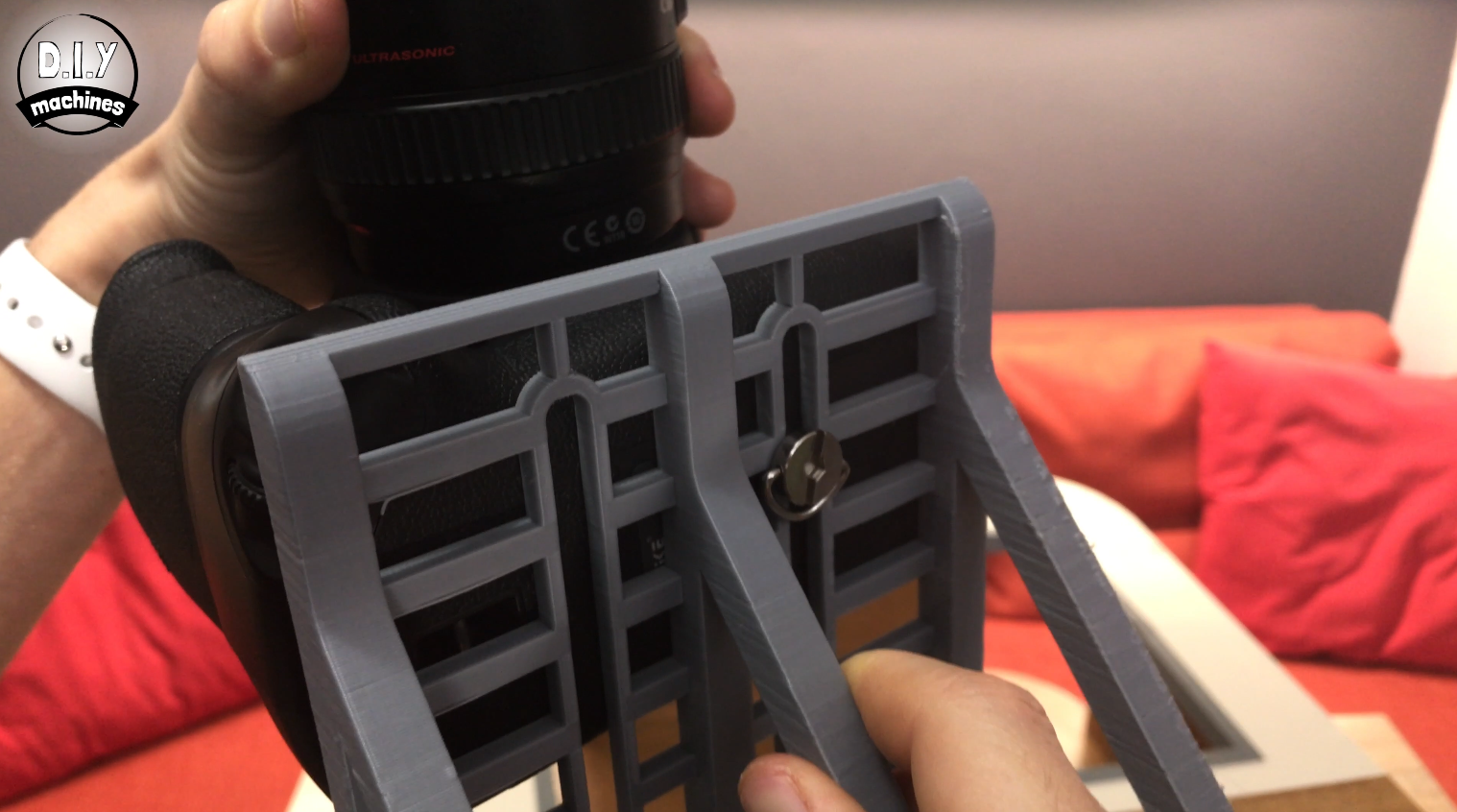
Let's mount the camera into the wooden housing. To do this we first need to attach it to the 3D printed mount. I used the thumbscrew from my tripod. You can secure it using the slot on either side of the print. Don't do it up too tight just yet as it needs to be able to slide up and down the length of the slot.
Slide it into the housing and position the lens within its cut-out. Use a marker to mark where the camera mount is positioned on the backboard so that we can remove the camera, then remove the back of the photo booth (this is why we did not cover the rear screws with Polyfilla earlier) so as to be able to easily screw the mount into place using the marks we just made for positioning.
Step 18: Installing the Monitor
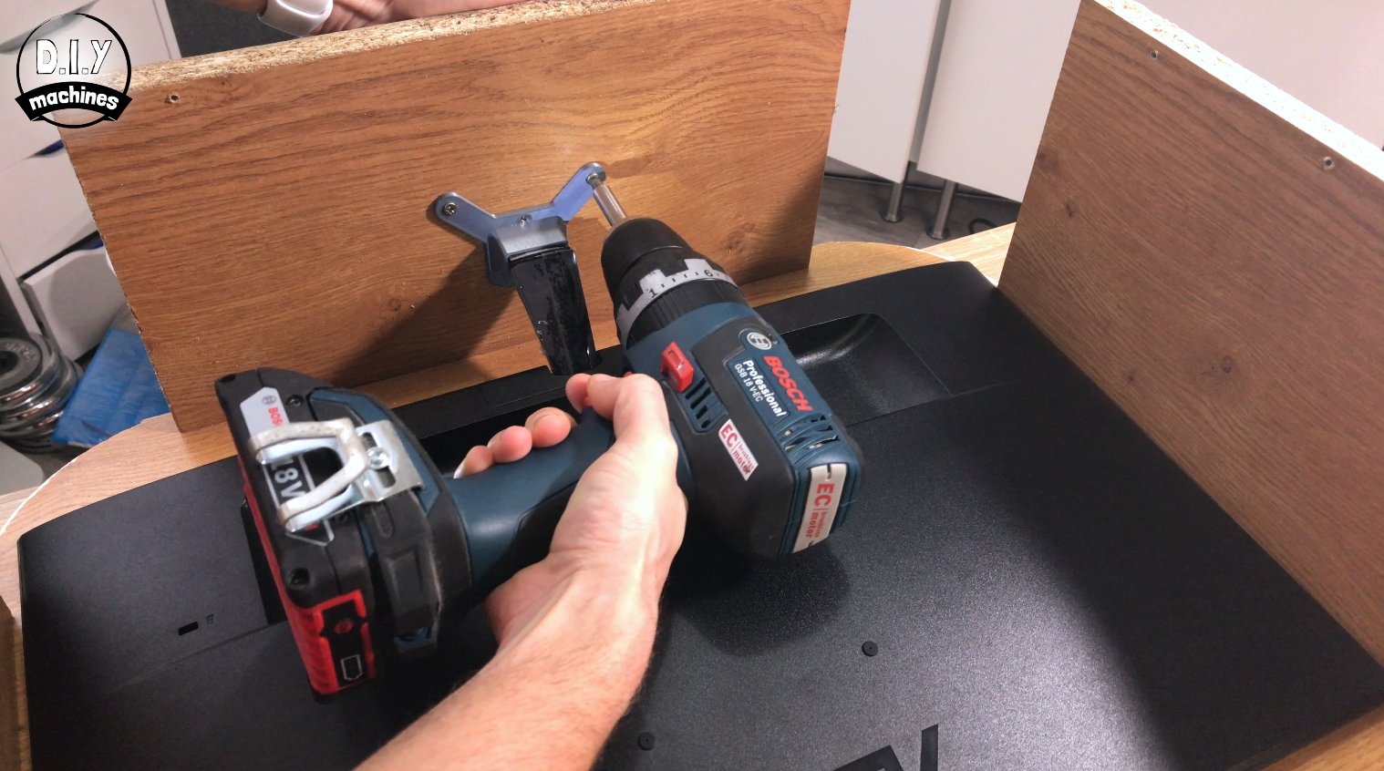
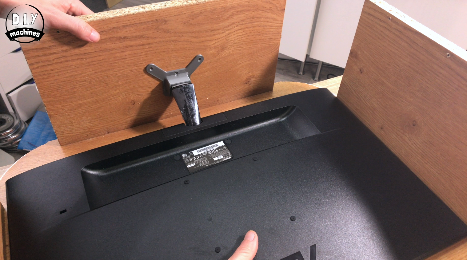
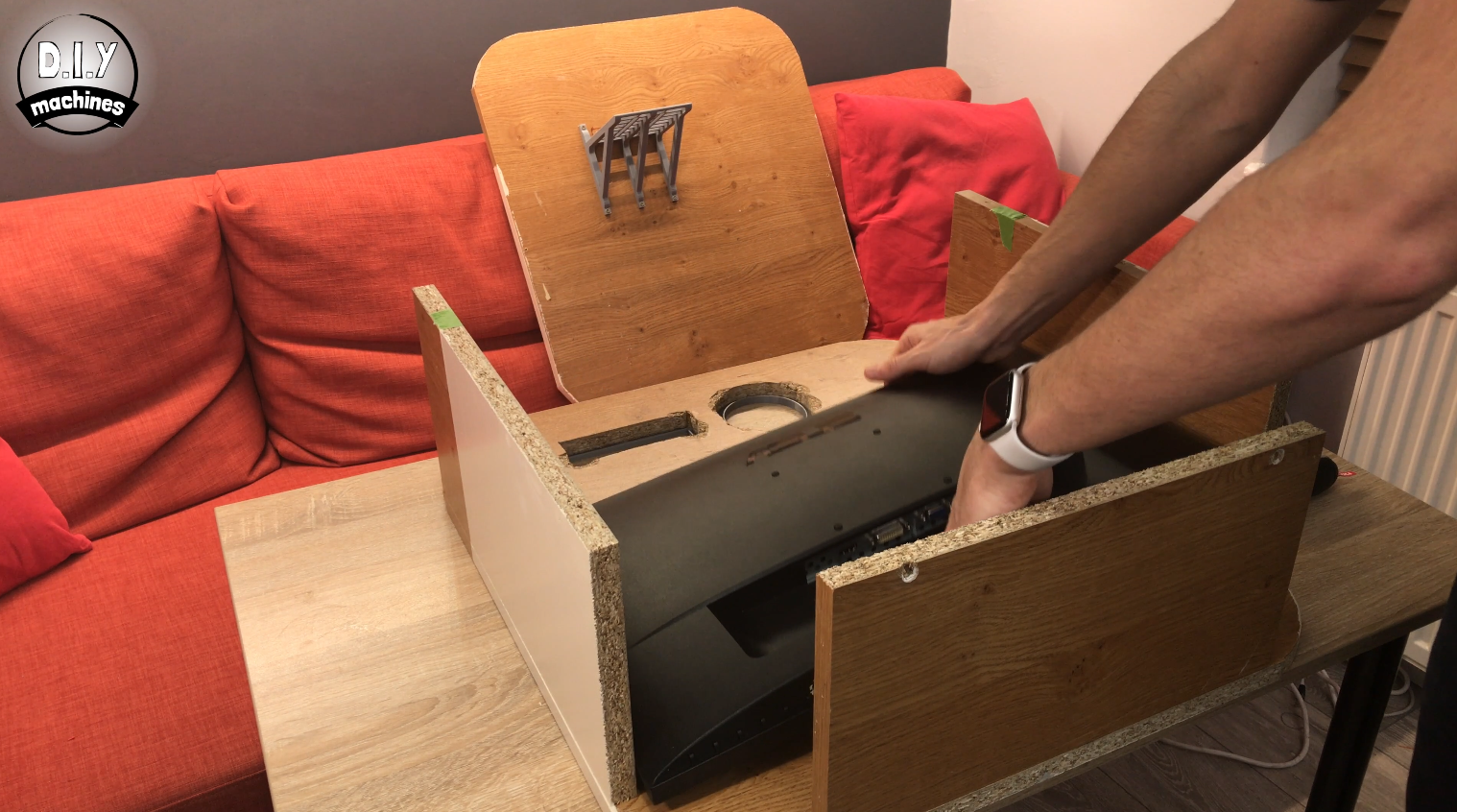
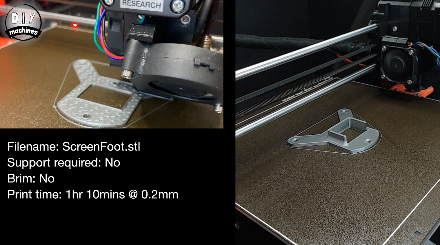
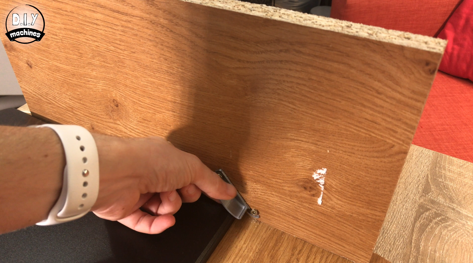
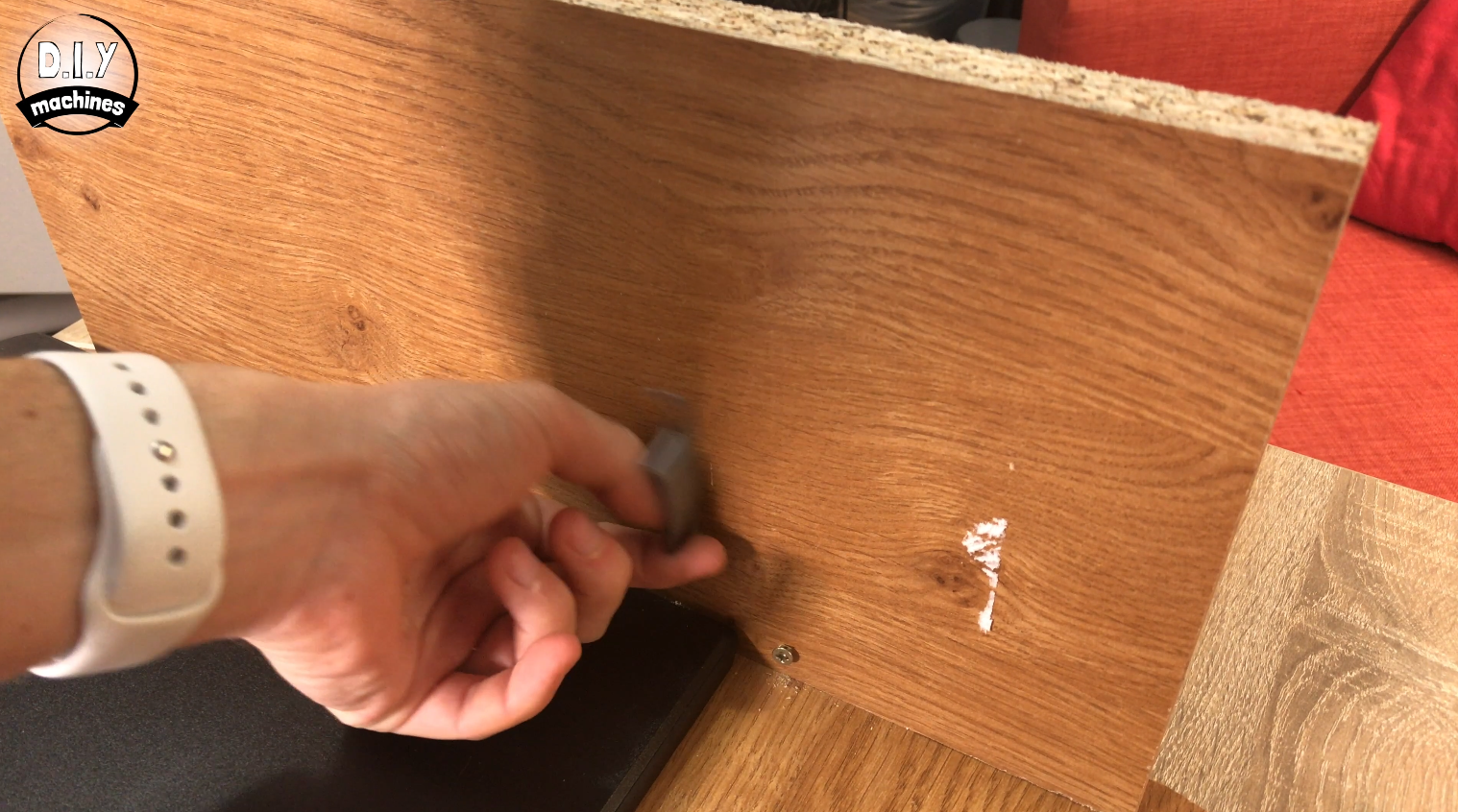
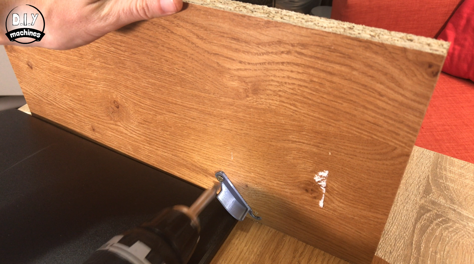
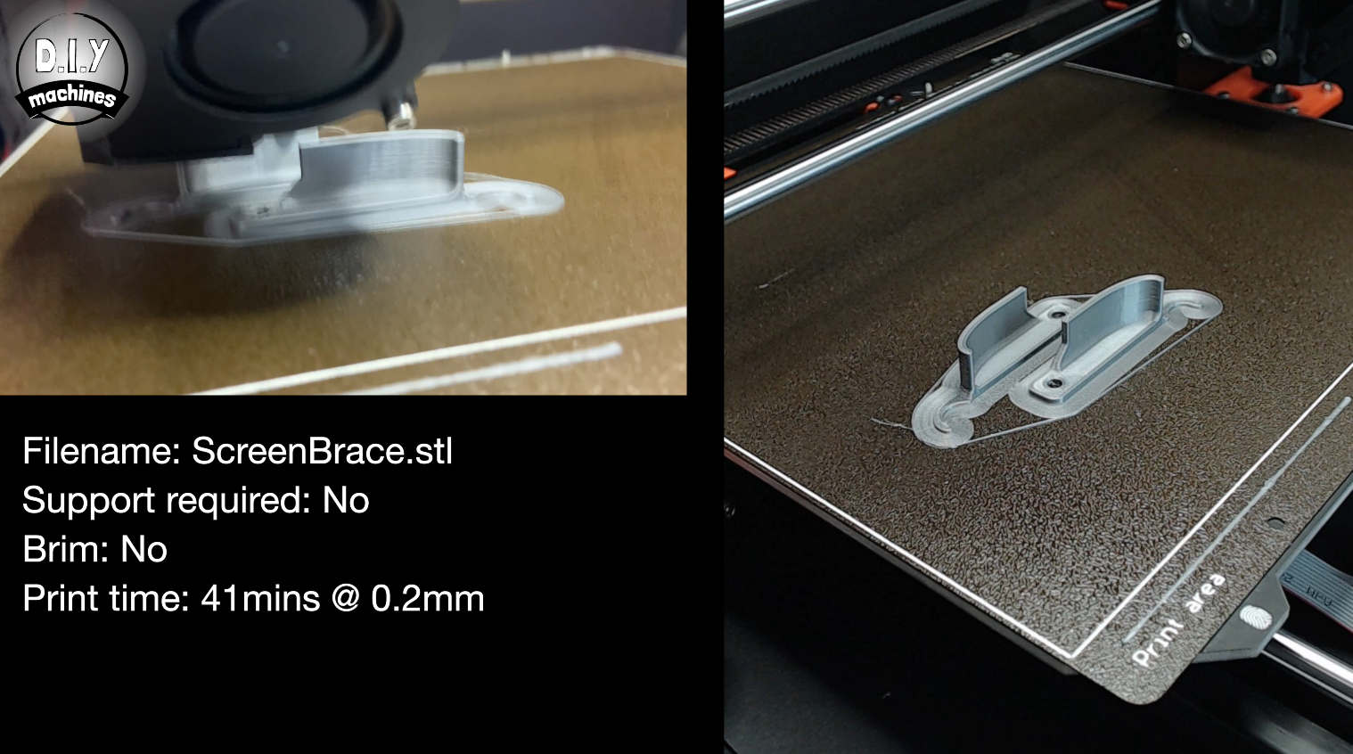
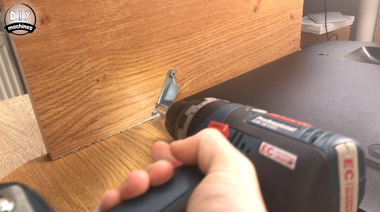
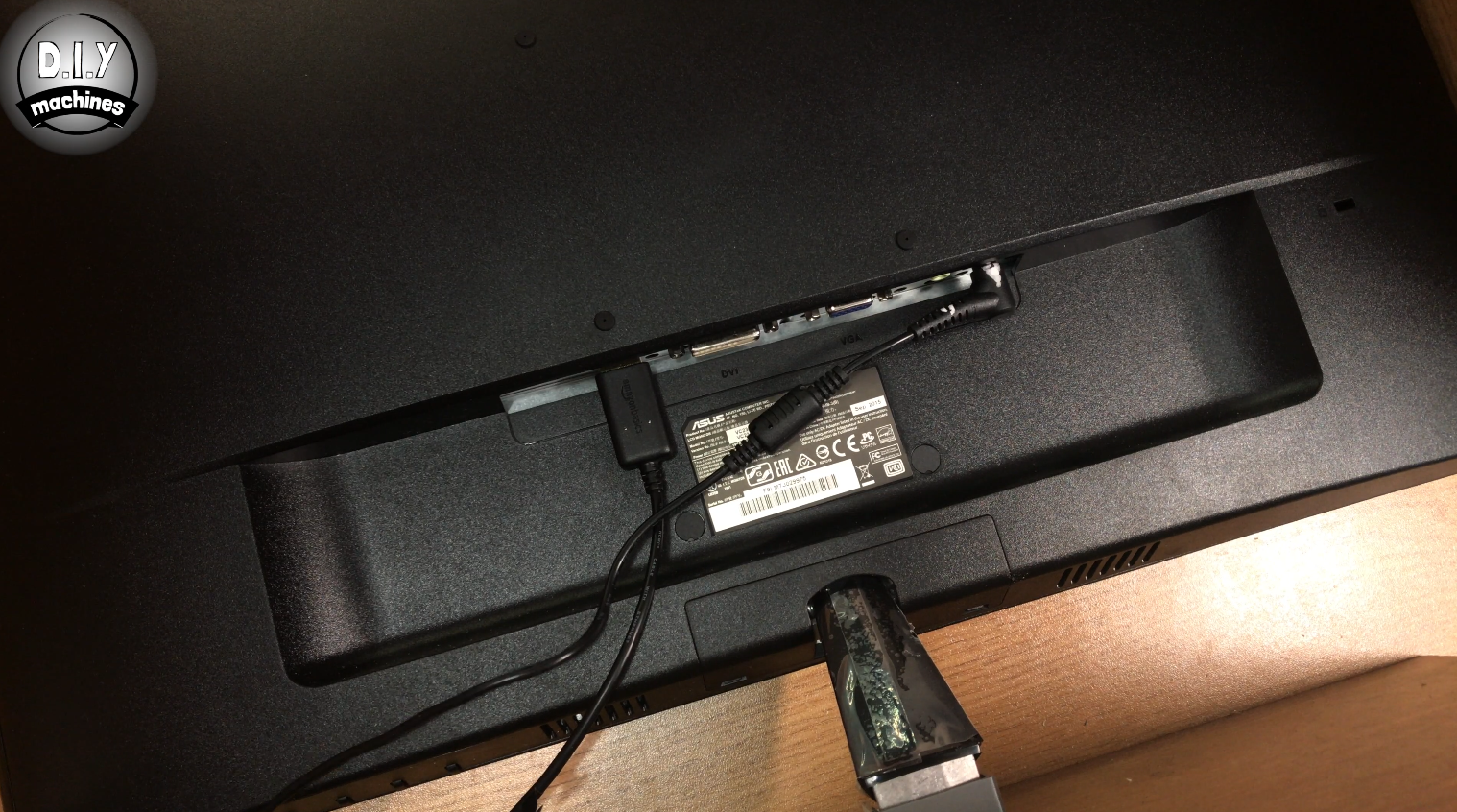
To secure the monitor in place we will use some more 3D printed parts. The first is ScreenFoot.stl. I printed this at 0.2mm layer height (which took about 1hr 10mins). To know where to screw this, place the monitor face down (without its manufacturers stand fitted) in the housing over its cutout and then lower the 3D print around the back of the 'foot'.
To prevent the monitor from falling out backward you need to print the two screen-brace files (they are handed). These are screwed into place near the top corners of the monitor. The screw which goes through the hole acts as a pivot, the second screw allows the 3D print to latch under or over it. This allows you to easily remove and re-install the monitor later.
Step 19: Installing the Electronics
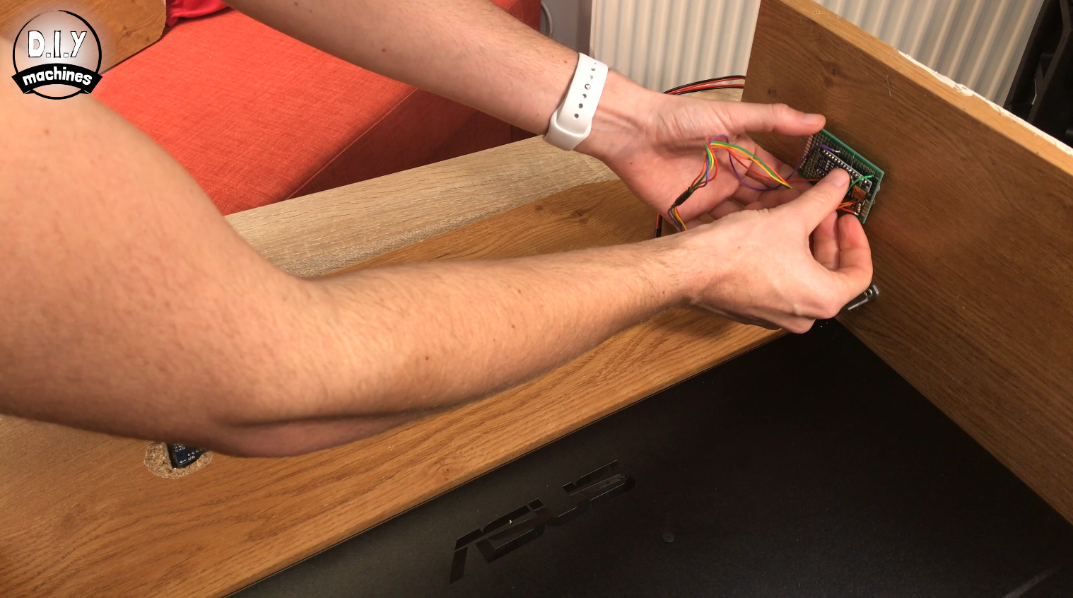
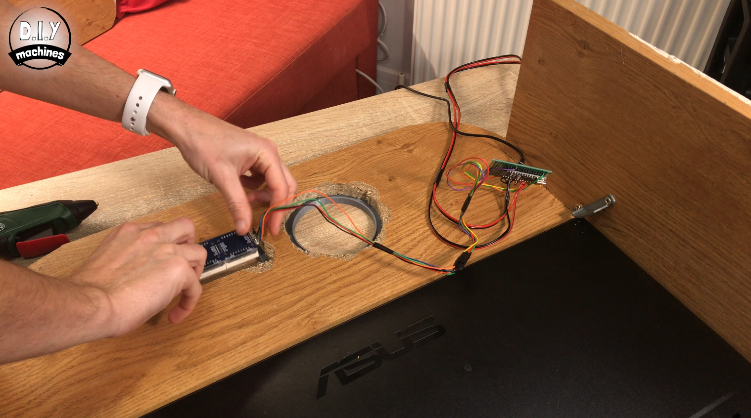
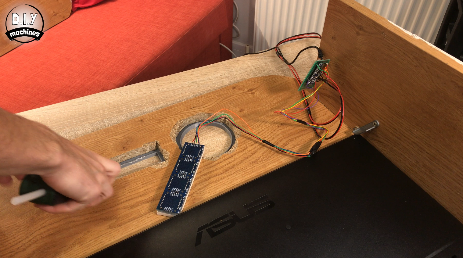
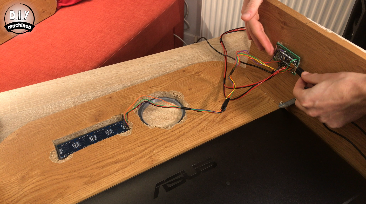
Use some hot melt glue around the inside of the LED Matrix trim we 3D printed earlier to hold it in place. Ensure that when looking at from the back, the writing on the module is back to front and upside down. This will mean it has been correctly installed for when seen from the front.
Use hot melt glue to attach your perforated circuit board to the inside side of the housing. If you opted for the breadboard then there is a good chance that it has self-adhesive backing on it which you can use. If not, hot glue should be fine.
Whilst we have easy access to the electronics it would also be a good idea to add a USB cable to the Arduino (to power it), the display cable for the monitor, and also the monitor's own power supply.
Once done you can re-attach the rear of the photo booth.
Step 20: Assembling the Illuminated Arcade Button
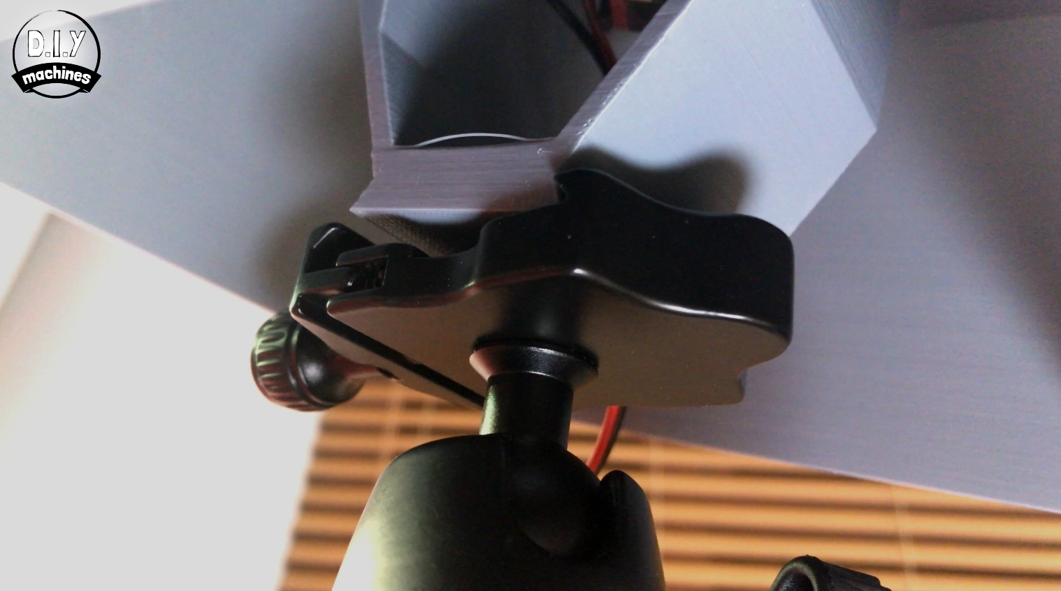
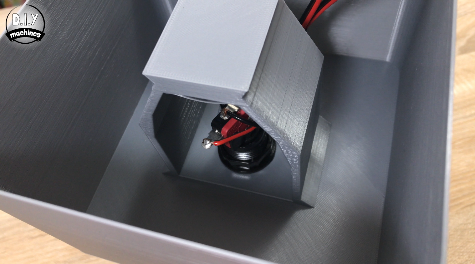
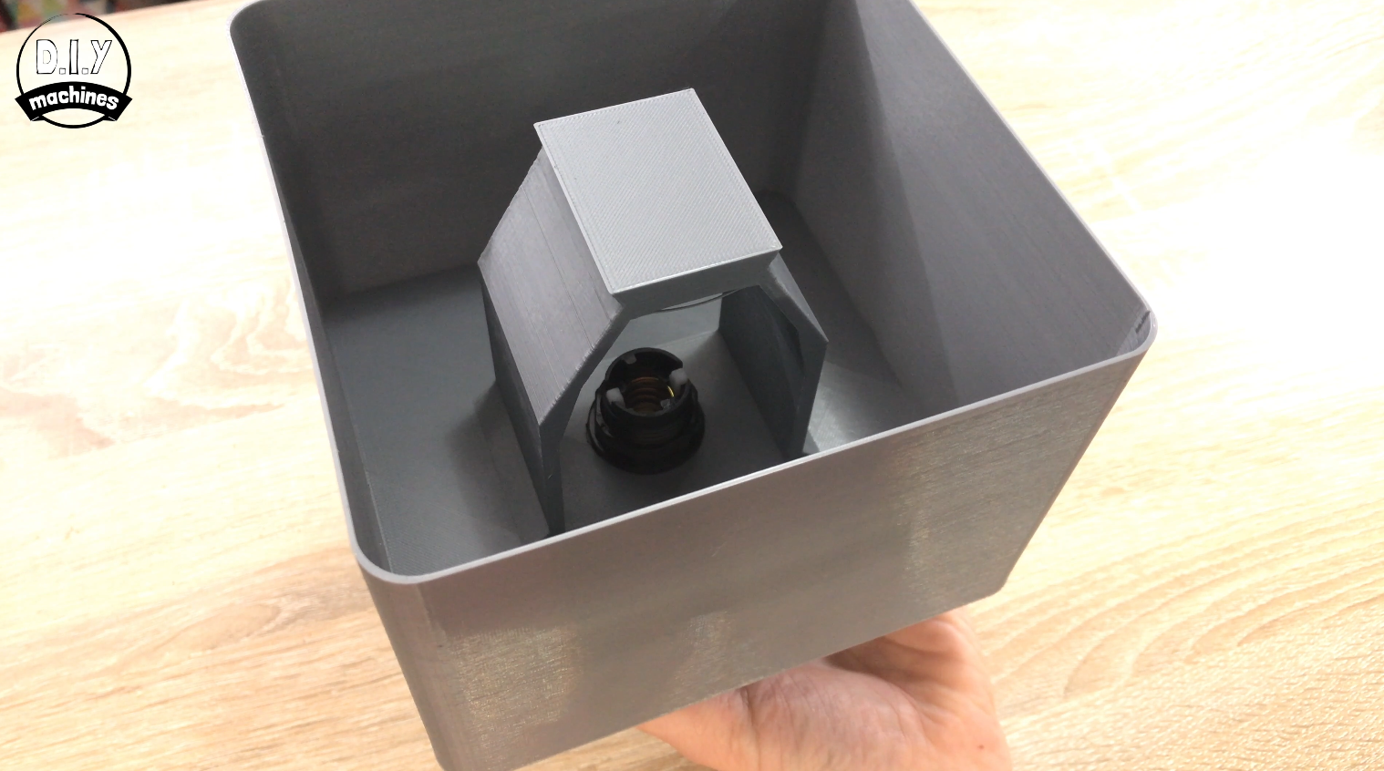
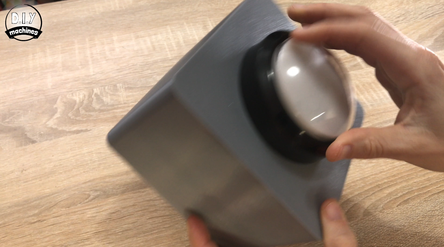
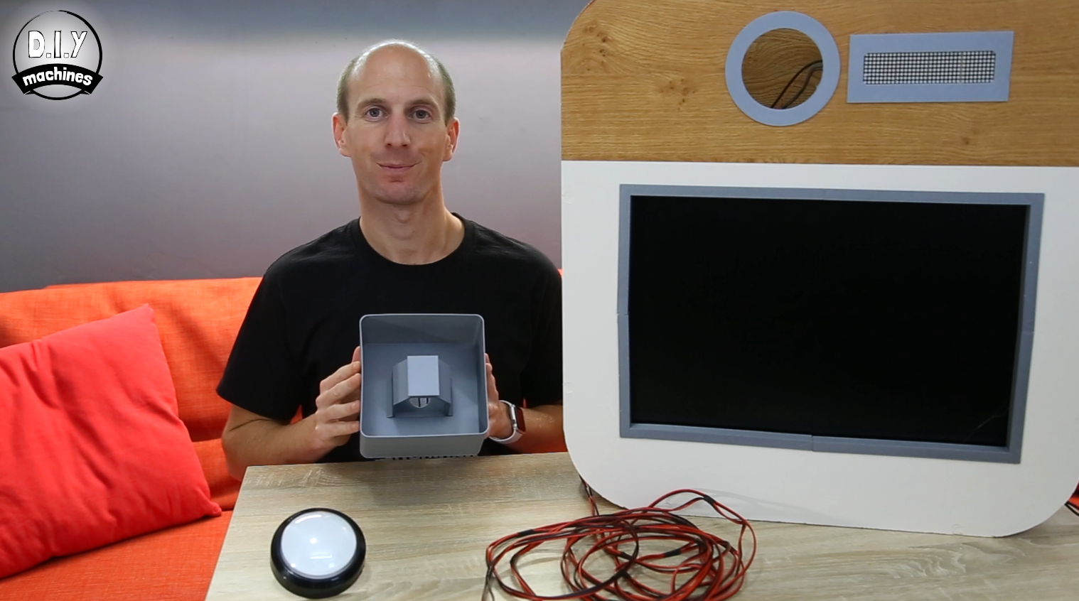
The arcade buttons mount is a 3D printed. I chose to use a layer height of 0.2mm and a higher print quality as the users of the photo booth will be close to this print and I wanted it to look and feel smooth.
The button is screwed onto the top of the print, then the electronics are reinserted from below. The whole assembly can then be mounted on top of a tripod for convenient positioning and adjustment.
Step 21: Camera Setting and Connecting
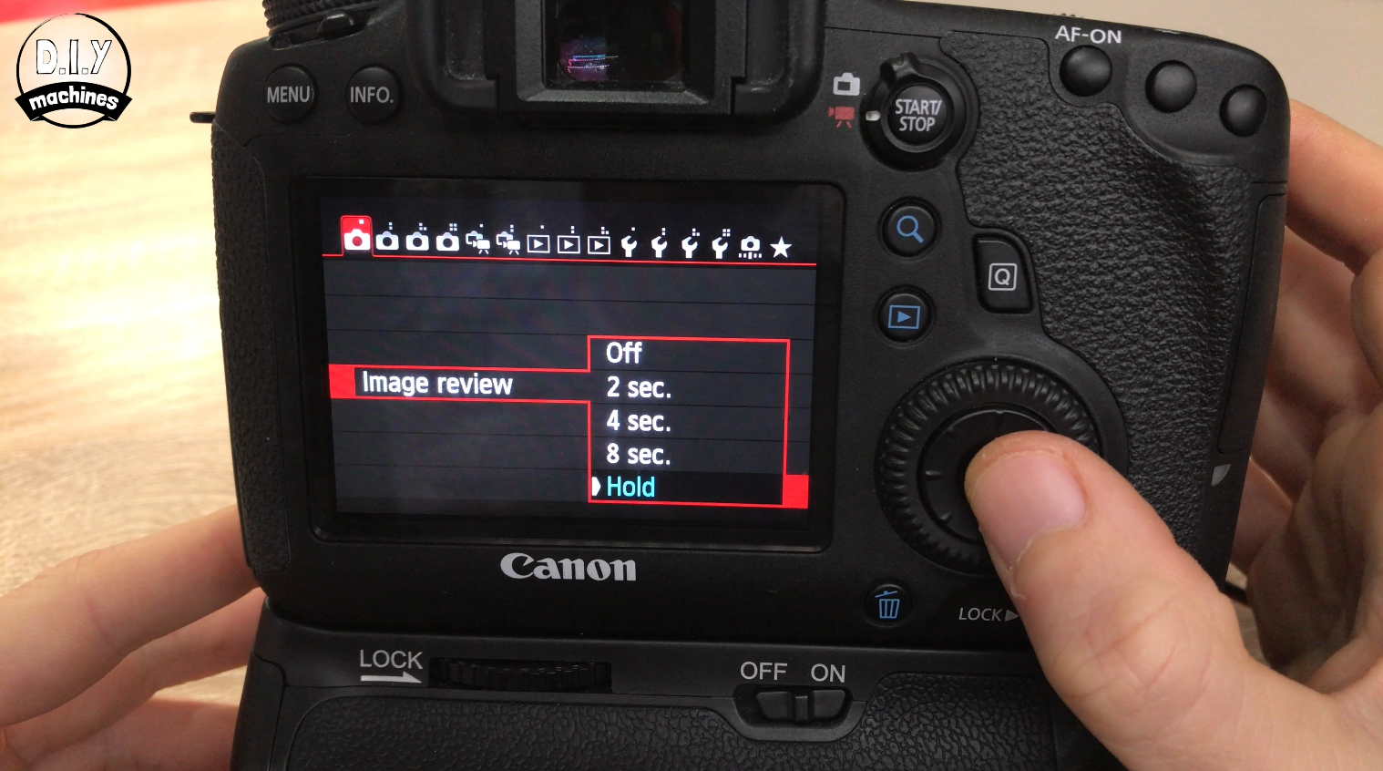
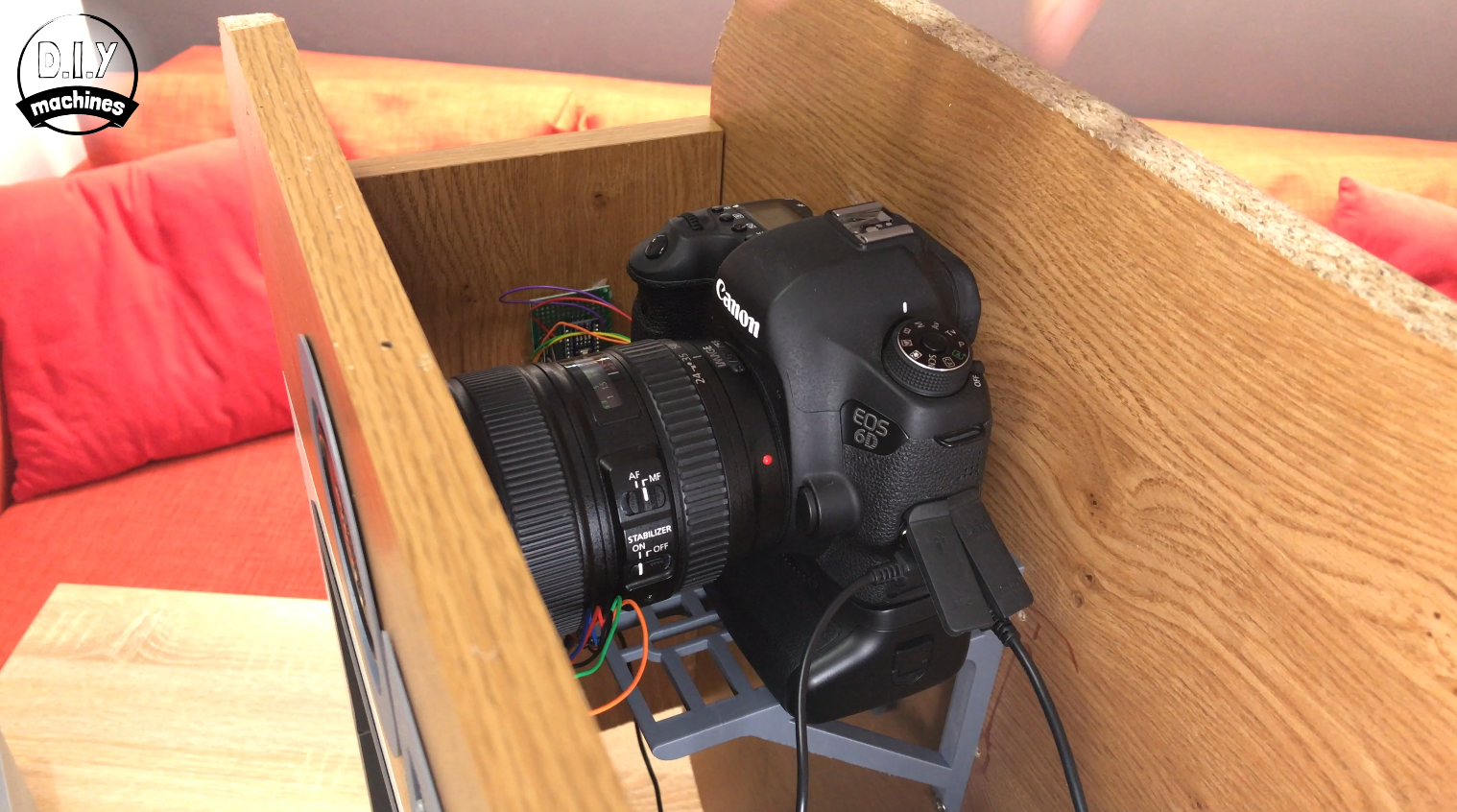
I left my DSL on full auto including the focus. I also dived into the menus and settings to set the 'Image Review' to 'Hold'. This means that after a photo has been taken it will remain to review on the large display until the next photo has been taken.
The camera can now be put back on top of its mount and screw can be reinserted from below to secure it in place. This time it's worth doing firmly to prevent the camera from moving too much. Then we need to connect the video cable to monitor which in my case is a mini HDMI connection. The other lead we need to connect is the camera shutter from the Arduino.
Step 22: Completed
Now you should be able to switch the camera, monitor, and Arduino on ready to take some photos, hit the Arcade button and (if no one is looking) strike some poses!
I hope you enjoyed making your own. Don't forget to take a look at some of my other projects. :)
Lewis


Leave your feedback...